ECE
476 Final Project
Ultrasonic
Spotlight Tracker
Paul Cheng Po Chen (cc323)
Jimmy Chin-Hao Chen (cc425)
May 2006
Introduction
A spotlight that follows you on its own!
The ultrasonic spotlight tracker is a system that uses a wireless beacon to track a target’s location using both RF signals and ultrasound waves. It then drives a light source to point at the location of the target.
High Level Design
The motivation for an automatic spotlight tracker is to replace expensive manual labor in operating spotlights in theatrical settings. There are also numerous other applications where knowing the real-time location of a remote target can be useful.
In this project,
we limit our remote unit’s degree of freedom to two dimensions to prove the
concept, although it can be very easily extended to three dimensions. To locate the target, we need to measure
the distance of the target from at least two known points. The distances are measured by counting
the time it takes for sound to travel from the target to the base station and
multiplying it by the speed of sound waves. The speed of sound in air is about 334
meters per second. The 16 MHz
microcontroller can count time intervals on the order of 0.0625 microseconds,
which gives a theoretical accuracy of
Once we obtain the two distances from two known points to the target, we can calculate the coordinate of the target point using a technique called trilateration:
Define the target point to be (x3,y3), and given two known points (x1, y1) and (x2, y2), the distance d1 from point 1 to target, and the distance d2 from point 1 to target, we can write down the following two equations:
![]() (1)
(1)
![]() (2)
(2)
To simply the solution, we set y1 = y2 and substitute x2 with s + x1. Solving equations 1 and 2 for x3 and y3, we obtain the following expressions:
![]() (3)
(3)
![]() (4)
(4)
We can then use this coordinate to calculate the angle for the spotlight using tan-1(y/x).
To start the timing of the sound wave, we use a RF transmitter/receiver pair to trigger an ultrasonic response from the remote unit. As soon as we finish transmitting the RF signal, we turn on the timer in the microcontroller to keep track of the traveling time of the sound. The ultrasonic response triggers an external interrupt on the microcontroller of the base unit to stop the timer and proceed to calculate the distance from the time.
Hardware
The hardware section is divided into two parts – the remote unit and the base unit.
Remote Unit
The remote unit consists of a MEGA32 microcontroller on an ECE476 custom PC board from spring 2005 with a RF receiver RCR-433-RP and an ultrasonic transducer (shown below in Figure 1). It is powered by a 9V battery with a regulator that keep the voltage at Vcc to be +5V. The RF receiver antenna passes through a low pass filter as suggested in the Radiotronix example circuit notes (see references). Since the default output of the receiver is +Vcc, we need to first pass the signals through a common emitter amplifier to invert the logic state before sending it to the RX of the UART port (PORTD.0). The ultrasonic transducer is driven by OC2 (PORTD.7) which toggles between logic high and low during fast-PWM mode when counter 2 is turned on. It is triggered by the RF signals received, and turned off after a pulse of 50ms. The operating frequency of the transducer is from 23 kHz to 25 kHz, and therefore we drive the transducer with square wave at the center frequency of 24 kHz.
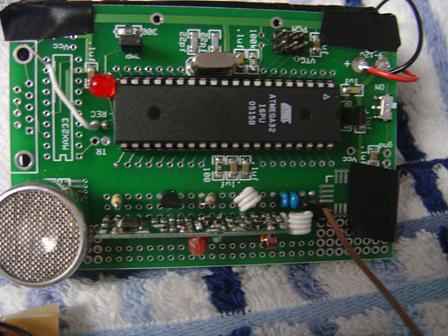
Figure
1. The remote unit with a RF receiver and a ultrasonic transducer
Base Unit
The base unit also consists of a MEGA32 microcontroller on an ECE476 custom PC board from last year, but with only a RF transmitter (shown in Figure 2). The RF transmitter RCT-433-AS sits in one corner of the PCB and the microcontroller UART TX (PORTD.1) first goes through a common emitter amplifier to invert the logic before going into the control terminal of the transmitter for the similar reason for the RF receiver in which the UART signal is high when it is not sending data, and this would cause the transmitter to constantly send logic one, which would consume much more power and violate the regulations of FCC. For convenience, we also built a peripheral board using solder boards and jumped wires from PORTC, INT0 (PORTD.2), INT1 (PORTD.3), INT2 (PORTB.2), and OC2 (PORTD.7). The connections from PORTC operate a LCD, which is used for debugging and displaying results. The external interrupt inputs INT0, INT1, and INT2 are used to watch responses from the remote unit. The OC2 signal is used to drive the servo motor, which is carrying a small flash light that acts like a spot light source. The center of the servo motor is defined as the origin in our system coordinate, and its angle of rotation can be easily calculated once the coordinates of the target is known.
We built 3 ultrasonic receiver units to attach to the base unit microcontroller. Each receiver consists of an ultrasonic transducer, a LM358 operational amplifier, a LM567 tone decoder, and some resistors and capacitors to make everything work. Specifically, the operational amplifier is set up to amplify AC signals since the transducer is like a capacitor that outputs a 24kHz sine wave with no DC voltage. The gain of the amplifier is set to 100 by the 100k Ohm and 1k Ohm resister feedback. The output of the amplifier is AC coupled to the tone decoder with is tuned with some resisters and capacitors such that its output will be driven low when the input is at or around the frequency of 24 kHz. Each of the 3 ultrasonic receiver unit’s output is connected to the 3 external interrupt pins and they will trigger the interrupt when they receive the sound signal from the remote unit. It turns out that the op-amp gain of 100 is slightly too large and the intrinsic noise of the transducer gets amplified to be about 100mV when we do not transmit the ultrasound. This gets picked up by the tone decoder and treated as a valid signal and asserts that there is an incoming tone at 24 kHz. To fix this problem, we found that we can put a piece of tape onto the opening of the transducer and it will reduce the noise from the transducer. However, it is not very tightly controlled, so the sensitivity of the ultrasonic receivers depends on how well we place the tape and how thick or flexible the tape is.
The base unit is also used to control a servo motor that will point a spot light in the angle desired. The motor runs on a voltage between 4.8V to 6V and we chose to use 4 AA rechargeable Ni-MH batteries to run it at 4.8V. The motor power supply is isolated from the microcontroller by the use of an opto-isolator. The driving signal goes from pin OC2 to the opto-isolator then gets amplified by 2 stages of common emitter amplifiers before going into the signal wire of the servo motor (yellow wire).
The servo motor will hold a particular angle when it sees a pulse of width 1 ms to 2 ms, with 1.5 ms being the center neutral position. The period of pulses should be around 20 to 25 ms.
The RF part is particularly tricky to make it work. In the beginning we have a hard time to get the receiver to receive the correct two bytes. We later added an aluminum plate to the back of each PCB with electrical tape as isolation so it does not short out the other components on the board. The aluminum plate is connected to the ground terminal on the board and it acts as a ground plane for the antenna. This seemed to improve the RF transmission immensely.
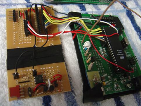
Figure
2. The base unit with a RF transmitter and the peripheral board
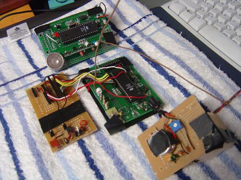
Figure
3. The front views of the base unit, the remote unit, and the center anchor
node
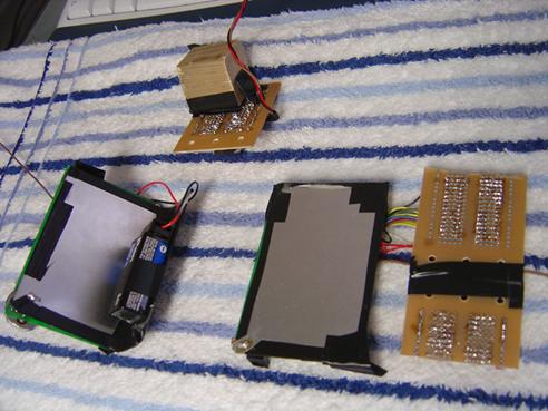
Figure 4. The back views of the base unit,
the remote unit, and the center anchor node;
the aluminum metal plates are the ground
plains for the RF transmitter/receiver pairs
Software
The software on the remote unit is pretty simple. The only thing it does is to listen for a particular byte sequence from the UART receiver and drives the ultrasonic transducer with a 24 kHz square wave for a few ms. The receiver code is partly based on Meghan Desai’s OOK wireless packet protocol. It first waits for the synchronization bytes, then the start byte, and then two more bytes which we chose at random to be 0b10001011 and 0b10110100 (which corresponds to the first and last codebytes used in Meghan’s protocol). If these two bytes are received, then the microcontroller drives the ultrasonic transducer for 50 ms.
On the base station, the microcontroller starts off by calibrating each of the 3 ultrasonic receivers first. It assumes the receivers are placed at their fixed known positions and the remote unit is also placed at a pre-determined location, and queries the remote unit to get the time of travel of sound from the remote unit to each of the sound receivers. Since we know the distance from the remote unit to the receivers, we can calculate the actual time it takes sound to travel that distance. The difference between the time it measures and the theoretical time is the offset for that receiver. Whenever an offset value is calculated, we check if it is within 5% of the running average value. If it is, then we add it to the running average and increase a counter by 1. If this condition is satisfied 3 times in a row, then we consider the calibration completed for that receiver. All 3 receivers will be calibrated this way or until a set number of trials has reached and at that point the system goes into distance measuring mode. In this mode, the base station queries the remote unit in the same manner as before, but when it gets a response, it will use the time to calculate the distance between that receiver and the remote unit, using the offset obtained during calibration.
While the system is measuring distances, it will check if any two receivers have obtained distance data. If so, it will use these two distances and the location of the two receivers to calculate the location of the remote unit using trilateration described in High Level Design section. If the location is successfully calculated, it will then calculate the angle that the servo motor needs to turn to direct the spot light onto the target. The angle is then translated to a pulse width duration using the timer compare register OCR2. Timer 2 is responsible for generating each pulse, and Timer 0 is used to count milliseconds and every 25 ms the microcontroller will as timer 2 to send out a pulse of a particular width to control the servo motor to turn to a particular angle.
Result
Our system is able to calibrate itself fairly quickly on a good day and provide distance measurements with accuracy of about ±2 cm. The distance and location shown on the LCD indicate that the results vary from time to time, and suggest that we should do some kind of averaging to smooth out the response of the spot light.
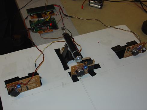
Figure 5. The Ultrasonic Spotlight Tracker in
operation
Safety
All protoboards and metal sheets are carefully filed and/or protected by duct tape or electrical tapes so that its edges do not present any danger of harming people’s skins upon touch. The system is automatic and the only operating procedure is to turn on the power switches on the remote unit and the base unit. The remote unit could be carried on a person, and its 9V battery provides safe power supply to the device while on the person. There is no RF transmitting devices on the remote unit so radiation to the body is relatively low. Since ultrasound cannot be heard by humans the device does not introduce any sort of annoyance problems.
Usability
The Ultrasonic spotlight tracker can be used in a larger setting with improved range to automatically operate a spotlight on a theater stage. This can potentially save on cost of hiring professional spotlight handler to be present for each light source. Other than the application of spotlight, many things can be done using the coordinate information obtained using this system, such as employee monitoring and automatic monitoring camera steering (such as watching a baby or pet).
Standards
We used standard 9V batteries for the remote unit power supply, and a standard 9V power supply for the base unit with a positive center. We used standard LCD modules with the driver that comes with the microcontroller. We also use the standard servo motor and its pulse width modulated operation and signal timing.
Conclusion
There are many
tricky parts in this project, particularly the RF ground plane and transducer noise
problem. This makes the system
performance less stable than the ideal.
We are happy to see that the tracker responds to the moving target,
albeit slowly. The LCD shows the
numeric results that is quite reasonable and this is the first step towards
making it a really usable system.
There are many things that we can improve upon, particularly the
ultrasonic parts. We think that
maybe the transducers themselves are of low quality since they are only $
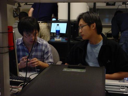
Figure 6. A picture of Paul and Jimmy debugging the
Ultrasonic Spotlight Tracker
One of the major drawbacks of this system is that the tracked target must carry this battery operated device in order to be tracked. There are other systems which involves image processing that does not require any device to be carried and rely on sophisticated algorithms and processing power to achieve tracking. It would be hard to apply our system to a defensive security system because it is necessarily hard for the adversary to carry a tracking device on hand.
Intellectual Property Considerations
We used parts of Meghan Desai’s design for wireless OOK protocol. We simplified the protocol because we essentially did not need to send any data. Our method of locating an object wirelessly is very well known and they should be considered public domain knowledge. If we can make the system very robust and reliable, then there may be a chance of making a patent out of it.
Ethical Consideration
In developing this project, we followed the code of ethics in our labs and with our peers. We think it is important for us to follow this code so that everyone will get the benefit of the resources provided to us and make it a nice working environment for everyone.
1. to accept responsibility in making
decisions consistent with the safety, health and welfare of the public, and to
disclose promptly factors that might endanger the public or the environment;
2. to avoid real or perceived conflicts of
interest whenever possible, and to disclose them to affected parties when they
do exist;
3. to be honest and realistic in stating
claims or estimates based on available data;
4. to reject bribery in all its forms;
5. to improve the understanding of
technology, its appropriate application, and potential consequences;
6. to maintain and improve our technical
competence and to undertake technological tasks for others only if qualified by
training or experience, or after full disclosure of pertinent limitations;
7. to seek, accept, and offer honest
criticism of technical work, to acknowledge and correct errors, and to credit
properly the contributions of others;
8. to treat fairly all persons regardless
of such factors as race, religion, gender, disability, age, or national origin;
9. to avoid injuring others, their
property, reputation, or employment by false or malicious action;
10. to assist colleagues and co-workers in
their professional development and to support them in following this code of
ethics.
Appendix A: Program listing
Source code in C for the base unit: base.c
Source code in C for the remote unit: remote.c
Appendix B: Budget

Appendix C: References
Datasheets:
Example Applications provided by the manufacturer:
Tone decoder
alternative data sheet with detailed explanations
Appendix D: Schematics
The followings are the schematics that we used to build our circuits.
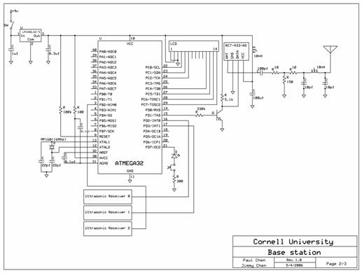
Figure 7. The schematics for the base station

Figure 8. The schematics for the remote unit
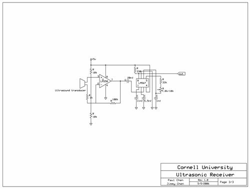
Figure 9. The schematics for the ultrasonic receiver
including the tone decoder
Appendix E: Task distribution
Soldering custom PCB and RF components Paul
Soldering ultrasonic receiver units Paul
Desoldering solder boards from scrap box Paul
Sampling microcontroller Jimmy
Testing and debugging software Jimmy
Deriving trilateration formula Jimmy
Appendix F: Vendors
digikey.com www.digikey.com
allelectronics.com www.allelectronics.com
Walt’s Hobby Inc. www.walts-hobby.com
Radiotrnoix www.radiotronix.com