
With LCD Touchscreen Controller
Jason Amsel
Konstantin Klitenik
Introduction
The clock is one of the oldest inventions in human history and has been used for centuries as in instrument for measuring time. There are many ways to implement this ancient technology by simple and practical methods. However, simplicity and practicality were not among the goals of this project. Instead, the project is intended to demonstrate an interesting application of available technology, and to create a visually appealing display in the form of a clock. Thus, the final product is more of a novelty item than a practical time-keeping device.
The design consists of two main components: an analog clock created from an old hard drive and some LEDs, and an LCD touchscreen which acts both as a synchronized digital clock and a controller for setting the time.
High Level Design
Rationale and Source of Ideas
There are several reasons why we choose to design the hard drive clock and LCD touchscreen controller for our final project. First, the idea fit well within our budget constraints since the LCD was sampled from www.microtipsusa.com and the hard drive was from an old computer on its way to the junkyard. In addition, the LCD and touchscreen drivers could have many useful applications beyond this project and could easily be incorporated into future work.
The idea of turning an old hard drive into a clock was motivated from a website by Alan Parekh. We wanted to expand and improve upon his concept and it seemed like it would be an interesting example of something the LCD touchscreen could control, as well as a clever way to re-use some old computer hardware.
Logical Structure
A block diagram of the overall system is shown below and a brief description is given for each main component.

Figure 1: Block Diagram of System
The LCD touchscreen controller acts as both a digital clock display and a controller to set the time. The LCD is a 320x280 pixel display which contains both a graphical layer and a text layer. The interface is based on the Epson SED1335 controller specifications. The device also includes a touchscreen with a TI ADS7843 controller which interfaces the microcontroller via SPI. The touchscreen is used to create 4 buttons for adjusting the time. An additional button is used to control the LCD backlight setting to one of three modes: always on, always off, or turn on when touched.
The LCD and touchscreen connect to the microcontroller board through a 26 pin cable.
The hard drive clock is created by cutting a slit in the upper platter of the drive. High powered LEDs are placed beneath the spinning platter. In addition, an optical interrupt switch is placed to detect the slit once per revolution. The clock hands can then be displayed by toggling the LEDs at appropriate times based on the slit position. Three different colored LEDs are used: red for the hour hand, green for the minute hand, and blue for the second hand.
Relationship of Design to Available Standards
The only applicable standard to this design is the Hours:Minutes:Seconds standard for displaying time. The relative timekeeping should conform roughly to the Coordinated Universal Time (UTC) standard, although the absolute time may be set by the user.
Existing patents, copyrights, and trademarks
The
Program/Hardware Design
MCU board
The Atmel Mega32 microcontroller is housed on the custom prototype board provided for ECE476. Several modifications were made to the board to accommodate our design. First a 26-pin dual row header was added to provide the interface to the LCD touchscreen. A separate 4 pin header connects to the LCD backlight. We also replaced the on-board voltage regulator with a more powerful LM340 5V regulator. This was necessary because the touchscreen LCD required several hundred milliamps of current.
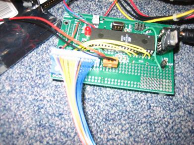
Figure 2: MCU prototype board
LCD/Touchscreen Hardware
The LCD touchscreen came with an EPSON SED1335 controller for the LCD and a TI ADS7843 controller for the touchscreen connected to a 26 pin connector. Thus, we only needed to provide the connections to these pins. The LCD and touchscreen drivers were implemented in software.
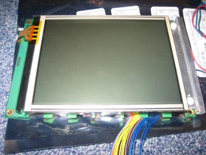
Figure 3: LCD touchscreen
Power Supply
The hard drive is configured with a 4-pin power connection to an ATX power supply. It was convenient to power everything (hard drive motor, LEDs, MCU, and LCD) off this same supply. As with the hard drive, the ATX power supply was taken from an old computer and did not cost anything.
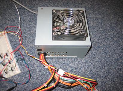
Figure 4: ATX Power Supply
Hard Drive Machining and Construction
We opened the hard drive and removed the read/write arm (including magnetic heads) as well as the voice coil magnets and arm cables. There were five platters but we only need the topmost and bottommost platters. When we removed the middle three platters, we had to account for their height and inserted an extra spacer to keep all the two platters and spacers tight and prevent vibration.
Next, we had to cut a slit 1/8 inch wide in the first platter. We used a dremmel tool with a grinder attachment which cut through the plate without any problems. Next we drilled three holes on each of the three sides of the drive for the LEDs.
The LEDs were mounted in the holes with a skillful use of the glue gun. We soldered the wires directly to the LEDs and ran them to the breadboard. Similarly, the optical slot switch was mounted on the yellow arm stop fixture.
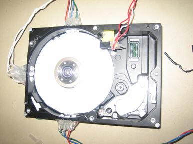
Figure 5: LEDs and optical switch mounted in hard drive
We cut out a white circle of paper and glued it to the bottom plate to reflect and diffuse the light from the LEDs. After everything was complete, we put the top platter back on.
The drive was ready…
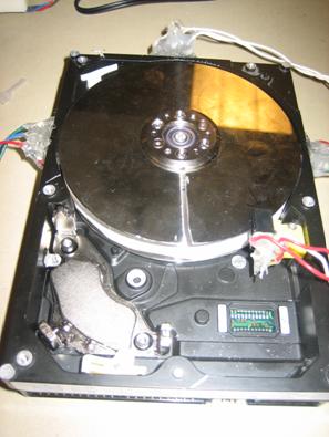
Figure 6: Finished hard drive with slit in top platter
LED drivers
The LEDs are from the THC3 series by LSDiodes. Their forward voltages and max currents are given in the table below:
Table 1: LED specifications
| Color |
Forward Voltage |
Max Current |
| Red |
2.4V |
100 mA |
| Green |
3.6V |
100 mA |
| Blue |
3.6V |
100 mA |
Since the LEDs are powered from a 12V source we were able to put two of each color in series. The series resistance can then be determined by
![]()
Since the LEDs are being pulsed with a small duty cycle, we were actually able to drive them with a current well above the maximum rating.
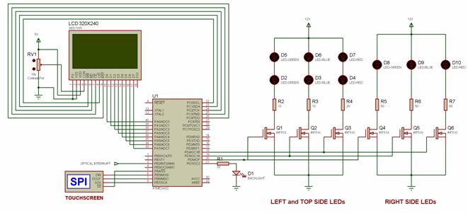
The LEDs and series resistors are connected between Vcc and the drain of an N-channel power MOSFET. The source is connected to ground and the gate is connected to an MCU I/O line. Thus, the LEDs can be turned on and off by toggling the I/O line.
The LED drivers were put together on a white board and wired between the hard drive and the MCU board.

Figure 7: LED drivers in white board
Optical Interrupt Switch
An H22A1 optical interrupt switch is placed across the disk in the lower right corner. This device has an optical emitter and detector separated by a slot which straddles the disk. The device is biased with a 2.5kΩ resistor on the detector side and a 60Ω resistor on the emitter side.
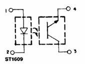
Figure 8: H22A1 Optical Interrupt Switch
Source: http://www.fairchildsemi.com/ds/H2/H22A1.pdf
When the beam is blocked by the disk, a HIGH level will be outputted by the interrupt switch. When the beam passes through the slit, a LOW level is outputted. Thus, an interrupt will be generated once per revolution.
LCD/Touchscreen Software
LCD Drivers
The LCD is a graphical (320x240 pixels) module with a built-in SED1335 controller and a DC-DC converter for the negative bias of the screen. The module was sampled from www.microtipsusa.com.
The LCD is interfaced according to Epson SED1335 specifications. The interface requires eight data bits (PORTA) and five control lines (Read, Write, Command, Chip Select, and RESET) which are on PORTC.4-0.
The physical interface is a parallel interface. Read and Write lines are used to latch in/out the data on the eight bit bus. Command line specifies whether an incoming byte is a data byte or a command byte.
The data is written to the screen by first sending a SET_CURSOR command byte to place the cursor at the desired location on the screen. Then a WRITE command is sent followed by the data byte. Reading data is accomplished in an analogous format, except after SET_CURSOR, a READ command is set and the data is latched out on the edge of the Read line.
There are many possible logical configurations for the display. It is possible to have a text layer and 2 graphics layers, or 3 graphics layers, etc. In addition, an overlay mode can be specified which allows logical AND, OR, and XOR of the layers.
Our screen was configured with the first layer as text layer and second layer as graphical. The overlay was set to OR which shows both layers, one above the other. The cursor was set to automatically advance to the left after data is read or written, which allows to read or write data continuously without having to set cursor position for every byte.
For complete specifications and greater detail see lcd_ctrl.c, sed1335.c, and the Epson SED1335 datasheet.
Touch Screen
The LCD module includes a resistive 4 wire touch screen with a built-in ADS7843 controller with an SPI interface. The controller is basically a 2 channel analog to digital converter. The conversion is started by sending a command byte which includes the axis (X or Y) and resolution (8 or 12 bits). Our implementation uses eight 8-bit samples per axis, which are averaged to improve accuracy. After the ADC value for each axis is calculated, the value is transformed into screen pixel coordinates. The transformation includes switching Y origin (0 value) from bottom to top and scaling both X and Y values to fit into 320x240 pixels.
Graphical User Interface
A GUI library is built on top of the LCD and Touch screen drivers. A GUI "widget" is defined by the four corner coordinates as well as its bitmap and a callback function pointer. When a new widget is created, it is added to the widget array and its bitmap is drawn at the specified coordinates.
The GUI is not time critical and, therefore, is polled every 5 milliseconds. If a touch is detected, the GUI goes through the array of widgets and determines if the touched coordinate is within any of the widget boundaries. If the touch falls within any of the widget, a corresponding callback function is called. The callback function contains the action to be taken as per desired functionality of the widget.
Bitmapping for LCD
To make an appealing visual display for the LCD, we wrote software to allow us to export .bmp image files to the LCD. This was accomplished using a bitmapping technique. A bitmap array is created as a two dimensional array corresponding to the rows and columns of the image. A loop then traverses through the 2-dimensional array bit by bit while simultaneously incrementing the LCD cursor position. A pixel is drawn (black) wherever a 1 is encountered in the current bit. No pixel is drawn (white) if the current bit is zero. This algorithm is contained in the function, SED1335_bitmap{} contained in Appendix A.
A MATLAB script was written to load a series of images and generate a header file containing the bitmap arrays. The first 4 values of the array correspond to the upper and lower bytes of the image width, and the upper and lower bytes of the image height, respectively. In order to use the MATLAB script the images are saved using an image name followed by a number (ex. image1.bmp, image2.bmp, image3.bmp., etc…). The script loads the images and performs a quantization to reduce each pixel to a single bit. A set of for loops traverse through the image array and write the pixel values to a .h file. As it traverses, fprintf is used to add appropriate formatting in between pixels so that it can be correctly interpreted as an array in C.
The MATLAB script in Appendix B is set up to open images (saved as image1.bmp, image2.bmp, image3.bmp, image4.bmp), and produce a header file, image.h, containing the bitmap arrays for the 4 images. The parameters can be easily modified to generate header files containing bitmaps for images with alternate naming conventions. The script was used to generate the header file, bitmaps.h given in Appendix A.
The entire LCD display was created from bitmapped images. This includes the title banner, the digits 0-9 used in the clock display, the backlight indicator, and the buttons for setting the clock.
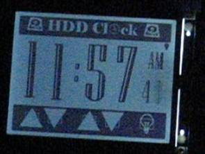
Figure 9: LCD display using bitmaps
LCD Backlight
The backlight consists of several bright white LEDs. We did not have exact specifications for the backlight so we put a potentiometer in series with the backlight and decreased resistance until the screen reached desired brightness without making the backlight hot. Then we measured the resistance and determined the current, which was around 20mA. Since the current is about 20mA, the backlight was driven directly from the MCU pin.
There are three options for the backlight: always on, always off, on when the screen is being touched. These options can be toggled by pressing the “Light bulb” button on the LCD screen.
GUI usability / Clock setting
The GUI is very user friendly and self explanatory. There are up and down buttons under hours and minutes. Pressing and holding the up button will increase hours or minutes. Similarly, pressing and holding the down button will decrease hours or minutes.
The leftmost button is the backlight mode button. Pressing and holding this button will toggle between three different backlight modes (in order):
Table 2: LCD backlight modes
| Mode |
Description |
| Always On |
the backlight remains always on. |
| Temporary On |
the backlight remains on while the screen is being touched and 2 seconds after |
| Always Off |
the backlight remains always off |
The backlight light bulb symbol near the AM/PM indicator shows current backlight mode. Filled light bulb represents always on mode while empty light bulb is always off mode. Half-filled light bulb is temporary mode.
General Timekeeping
Timekeeping for the clock is based off a 2 millisecond TIMER0 interrupt using the TIMER0 compare. This occurs when TCNT0 reaches the value in OCCR0+1. To generate the 2 ms interrupt a prescaler of 256 is used and OCCR0 is set to 124.
Four global variables are used, seconds, minutes, hours and am_pm are used to keep the time. A counter, count_2ms, is incremented each interrupt to keep track of the 2 ms intervals. When this reaches 500, 1 second has passed and seconds is incremented. Similarly, minutes is updated after 60 seconds, and hours is updated after 60 minutes. The am_pm variable is toggled each time hours reaches 12. Upon changing the time, a flag, lcd_update_ready is set so that the clock display will be changed to reflect the new time on the next iteration.
The time may also be set manually by using the time set buttons. When these buttons are pressed, the seconds, minutes, and hours variables are simply incremented or decremented accordingly.
Hard Drive Clock Time Display
The hard drive platter spins at 7200 RPM. Three different color LEDs are placed underneath the spinning platter with each color being controlled by a separate MCU I/O. The three clock hands are generated by toggling each set of LEDs at the appropriate times based on the slit position.
The output of the optical switch is connected to INT0 which is configured to enter an ISR on the falling edge. Thus, an interrupt will be generated each time the slit passes through the optical switch, once per revolution. Since the disk is spinning at 7200 RPM the period of the slit interrupt can be calculated as
![]()
We can then divide the clock face into 60 equally spaced position(6 degrees each) to represent the timing intervals. Thus, the time per clock interval can be determined as
![]()
Using these values, we can calculate the exact time at which the slit is at any given position. Each clock hand can then be generated by toggling the LEDs on at a particular slit position. A lookup table is used to map the minutes, seconds, and hours with an appropriate delay for each possible hand position. The timing for these delays is based off a TIMER1 compare interrupt. Timer 1 is configured with a prescaler of fclk/8 to give 500ns per timer tick. When the slit interrupt occurs, TCNT1 is set to 0 and the appropriate delay is determined based on the desired hand position. OCR1A is then set so that the TIMER1 interrupt will occur after the desired delay time.
For example, if we wish to place a clock hand at the 12 o’clock marker, we calculate (from the above equations) that the slit will be at this position 3.35 ms after it passes through the optical switch. TIMER1 COMPARE is set to 6700 ticks (500ns per tick) following the optical interrupt on INT0. Within the timer interrupt, the appropriate color LEDs are turned on for 20 μs and then turned off. We then calculate the delay for the next clock hand and set OCR1A accordingly. After all three clock hands are displayed, OCR1A is set to its maximum value so that no additional TIMER1 interrupts will occur until the next revolution.
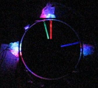
Figure 10: Hard drive clock hands display
Result of the Design
The implementation of the hard drive clock with LCD touchscreen controller was an overall success. However, several performance issues arose as discussed below.
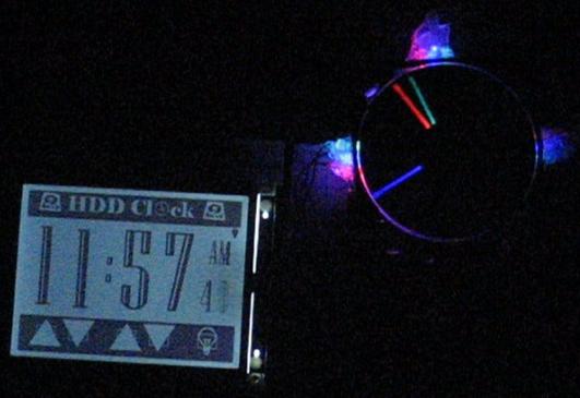
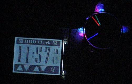
Figure 11: Finished Hard Drive Clock with LCD Touchscreen Controller Display
Clock Accuracy
The timekeeping is based off a TIMER0 interrupt and the digital LCD clock display should be accurate down to the accuracy of the crystal (±0.005%).
The accuracy of the hard drive clock suffered somewhat because the hard drive motor had a tendency to periodically slow down slightly and then get back up to full speed. The cause of this was likely due to vibrations from the spinning platters. We were able to alleviate this problem for the most part by placing the drive on a more shock absorbent surface. However, we would still get occasional slow downs in the motor speed. Since we depend on knowing this speed to position the clock hands, the result is that the clock hands move briefly out of position. However, once the motor returns to full speed, the hands will move back into the correct position.
This “flaw” was deemed acceptable because the clock hands move out of position only very briefly. Furthermore, the clock has no labeled numbers or tick marks, and therefore is only meant to provide an approximate time. Since the viewer would have difficulty determining the angle of the clock hand to within the 6 degree intervals anyway, a small imprecision in the positioning is of little consequence. Although the positioning of the clock hands may not be exactly correct to the degree, there is no associated drift apart from the drift of the crystal.
Touchscreen Performance
Due to the design of the touchscreen itself, the returned coordinates of a touch were not always consistent. This was mainly a problem when attempting to operate the touchscreen with our fingers which produce a fairly wide touch area. In order to alleviate this problem we used an averaging algorithm to determine the coordinates of any touch. While this helped, we found that best results were still achieved by using a stylus to interface with the touchscreen rather than fingers. This was an acceptable result, since many touchscreens are designed for use with a stylus.
Safety
The main safety concern from this project was the exposed spinning platter from the hard drive clock. This could potentially cause injury if it were touched when spinning, or could be dangerous if anything were to be dropped on the spinning disk. For the purposes of demonstrating in lab, we felt these hazards were not a major concern. However, if the hard drive clock were to every be sold, we would clearly have to address this safety issue. The most obvious solution would be to simply place a glass or clear plastic cover over the spinning disk. We did not do this during lab, because the hardware needed to be accessible for testing and debugging.
Usability
The hard drive clock and touchscreen LCD controller are very easy to operate. The GUI was designed to provide a very simple and straight-forward interface. The main factor that makes the project impractical for household use is the noise generated from the hard drive. It is likely far too loud for anyone to want this constantly running in their home. However, the project was never really intended for this purpose. Additionally, while the hard drive clock can be viewed in daylight, it is far more appealing to view it in a dark room. This also subtracts somewhat from the usability of the design.
Videos
The following videos demonstrate the project in action.
Video 1: Hard Drive clock and LCD Display
Conclusions
Analysis
The final results of this project met our design goals and expectations. While we did not encounter any major difficulties over the course of the project, we did end up in the lab for far more hours than we had originally expected. However, the end results were quite rewarding. There are several additional features that could have added to our design, but we were limited by our budget constraints. First, it would have been nice to add more LEDs, brighter LEDs, and wider variety of colored LEDs. This would have allowed us to create an even nicer display. Second, we would have liked to be able to package the entire device nicely together, instead of requiring a fairly substantial mess of wires. A custom designed PCB could have eliminated most of the external wiring and could be mounted directly to the hard drive. In addition, a case to cover the spinning disk would help decrease the noise and reduce the safety hazard of the clock. These additional features were not feasible due to our budget and schedule constraints.
Intellectual Property Considerations
The main intellectual property concern with our project is that the idea for the hard drive clock was based on a similar project by Alan Parekh. However, the design and implementation of the system was our own. Furthermore, we expanded upon the idea in several ways, including the use of the LCD touchscreen as a controller. If we were to apply for a patent on our design, we would have to be careful to make sure our implementation was a considerable non-obvious and useful deviation from previously designed hard drive clocks.
Ethical Considerations
This project was designed to conform to the IEEE Code of Ethics as follows:
1. to accept responsibility in making decisions consistent with the safety, health and welfare of the public, and to disclose promptly factors that might endanger the public or the environment.
The design poses only very minimal safety hazards, all of which are disclosed in this report. Furthermore, these hazards would be addressed if the design was removed from the laboratory setting.
2. to avoid real or perceived conflicts of interest whenever possible, and to disclose them to affected parties when they do exist;
There were no real or perceived conflicts of interest
associated with the project.
3. to be honest and realistic in stating claims or estimates based
on available data;
This report states honestly the results of this design.
4. to reject bribery in all its forms;
No opportunities to accept bribery arose during the course of this project.
5. to improve the understanding of technology,
its appropriate application, and potential consequences;
This project utilizes widespread technology and poses no potentials consequences to the technology.
6. to maintain and improve our technical competence and to undertake technological tasks for others only if qualified by training or experience, or after full disclosure of pertinent limitations.
This project was a great learning experience. While the goals were challenging they were not beyond the qualifications or training of the team members.
7. to seek, accept, and offer honest criticism of technical work, to acknowledge and correct errors, and to credit properly the contributions of others;
This report gives proper credit to both the team members, and outside sources from which ideas were borrowed or information was obtained.
8. to treat fairly all persons regardless of such factors as race, religion, gender, disability, age, or national origin;
No persons were treated unfairly during the course of this project.
9. to avoid injuring others, their property,
reputation, or employment by false or malicious action;
No people, their property, reputations, or their employment were injured during the course of this project.
10. to assist colleagues and co-workers in their professional development
and to support them in following this code of ethics.
By submission of this report, we will be able to assist future students in their development by providing an explanation of the technology in this design.
Appendix A: MCU Code
Header Files |
Source Files |
Appendix B: MATLAB Script for Bitmap Generation
Appendix C: Schematic
Appendix D: Cost Details
| Part |
Cost |
| White board |
$6 |
| Custom PC board |
$5 |
| Mega 32 |
$8 |
| LCD touchscreen |
$0
Sampled (microtips |
| Old hard drive |
$0 Found (old PC) |
| Power MOSFETs |
$0 Sampled (fairchild) |
| THC series LEDs (6) |
$10.44 ($1.74 each) |
| 5mm LEDs (3) |
$1.35 ($0.45 each) |
| Optical Interrupt Switch |
$0 Sampled (fairchild) |
| ATX Power Supply |
$0 Found (old PC) |
| Total: |
$30.79 |
Appendix E: Tasks
Konstantin sampled the LCD touchscreen and wrote most of the drivers for the SED1335 specification. All other tasks were shared by both team members and carried out in 476 lab. The following list provides a breakdown of the tasks:
- Write LCD Drivers
- Write Touchscreen Drivers
- Write Bitmapping Algorithms
- Design and implement GUI
- Develop timing algorithms
- Implement LCD backlight controller
- Solder MCU board and LEDs
- Breadboard LED drivers
- Machining Hard Drive
- Test and Debug
- Write Report
Appendix E: References
Datasheets
TI ADS7843 Touchscreen Controller
Vendors
Background reference