GoConn Bicycle Computer
ECE 476 Final Design Project
Jonathan Go (jtg28) and Ryan Connell (rbc24)
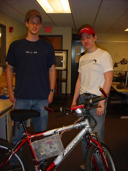
Jonathan Go (jtg28) and Ryan Connell (rbc24)
Introduction
This project is a bicycle computer that includes velocity monitoring, calorie computation, an audio/visual alarm, and a wireless remote.
Bicycles are great for transportation as well as exercise. Unfortunately, many bicycles across campus and around the world are stolen everyday. We designed a computer that would deter someone from stealing the bicycle while also providing information useful for exercise and transportation. Our computer provides information to the user that includes elapsed time, current velocity, and calories burned. The bicycle has a wireless remote which allows the user to lock and unlock the bicycle (you can also use the computer’s terminal on the handle bars to lock the bicycle). In the event someone attempts to sit on or move the locked bicycle an LED will flash and an alarm will sound, bringing attention to the event and allowing anyone in the area to intervene.
High Level Design
Rationale and Source of Project Idea
Bicycles are used around the world for transportation, leisure and exercise. Bicycle computers can help aid the desired use by giving additional information to the user while they are biking. Bikes are also stolen all the time, much to the dismay of the owner. We decided to create a computer that would give useful information to the user while they are riding, and also protect itself in some way from theft when it is left unattended. The wireless communication device was added out of curiosity and as the ultimate addition to any nerds set of wheels.
Background math
The mathematically intensive part of this project is the portion that calculates the velocity, distance and the calories burned.
To calculate the velocity of the user, a magnetic sensor was placed near the axis of the rear wheel. Attached to the wheel itself (and thus free-moving) is a magnet that, as the wheel spins, will pass directly alongside the magnetic sensor.
The circumference of the bicycle wheel we used was found to be approximately 81.75 inches, which is equivalent to 2.07645 meters. Calculating the average velocity is then found by counting the number of times the magnetic sensor “sees” the magnet, which gives a pulse to the microcontroller. The number of revolutions is multiplied by the circumference, and it is only a matter of converting into miles per hour. The velocity is also calculated in meters per second for calculating the number of calories burned.
This scheme was very inaccurate, so a different method was used to calculate the velocity, where the pulse to pulse length is determined to calculate the velocity. By doing so, the velocity can be calculated by dividing the circumference by the time length of the pulse. Using this methodology, the formula is
 ,
,
where C is the circumference of the wheel in miles and t is the time length of the pulse in hours. With all the conversion factors in place, the equation would be
 ,
,where t is in milliseconds and C is in inches.
The distance traveled is calculated simply by adding the circumference C every time the magnet is detected by the sensor.
The number of kilocalories burned is determined by the basic kinetic energy equation:
 ,
,where EK is given in joules, m is in kilograms, and v is in meters per second. In order to calculate the number of Calories (i.e. kilocalories) burned, the user must enter his or her weight in pounds. The microcontroller then converts this weight into mass in kilograms via the conversion factor 1 kilogram per 2.2 pounds. As the velocity is continuously updated, the number of Calories burned is also updated by using the equation above and the conversion factor 0.239 kilocalories per kilojoule. The final equation turns out to be
 ,
,
where w is weight in pounds, C is the circumference of the wheel in inches, and t is the pulse length in milliseconds.
Logical structure
The program has two different state machines: a small debouncer state machine, which determines when a button is actually being pressed or not, and a global state machine, which determines what is currently being shown on the LCD display. There are eight different states, defined in the enumeration state. The state diagram for the state machine is shown below.

The state machine is fairly circular, with transitions in the outer loop based on the user decision to press the left button or the right button. The transitions from any state to the LOCKED state can be done by pressing the remote control. The transition from LOCK to LOCKED can also be done by pressing the OK button. After the system is “unlocked”, that is, when it leaves the LOCKED state, it always enters the DISPLAY TIME state.
With this, the update function is called continuously (once every 100 milliseconds), and if the proper buttons are pressed, then the function updateState is called to perform the state transition.
Another state machine is implemented in the debouncer function, which performs debouncing of the buttons to ensure that there is minimal noise with button presses and releases. The code for this portion of the project is credited to Professor Land. Slight modifications were implemented to make the debouncing inputs easier to change by using a #define call.
Hardware and software tradeoffs
In implementing the wireless transmitter and receiver, instead of using another microcontroller to transmit data, an encoder circuit was used. This served to reduce the budget by allowing us not to buy another microcontroller unit and coding a protocol for encoding into it. The decoding of the signal was also done in hardware instead of software, to facilitate use of the microcontroller resources and perform tasks that were extremely difficult to implement using pure hardware. Using the decoder circuit allowed the signal from the encoder to reach the microcontroller as a digital high signal instead of a stream of data.
Similarity to Other Designs
We found bike computers online from about $15 to $85. They offered many different options including current velocity, average velocity, max velocity, odometer, timer, altimeter, and a compare with the average to see if you are keeping pace with yourself. We also found a bike alarm called bike guard that comes with a wireless remote and has a siren that goes off if the bike is disturbed. We weren’t able to find any products that included everything compiled into one product.
Program/Hardware Design

Software
The software was fairly simple to write. Our major problems were encountered when the hardware (i.e. the STK500s in lab) did not work as intended. The first instinct was to check the software thoroughly before figuring out that the hardware was giving us grief.
A nice little trick in the software is blinking the digit that is currently being edited. This is done when the user enters in the password to unlock the bicycle.
A tricky part to write was the portion that determines the pulse to pulse length of the magnetic sensor. It was important to realize that not setting a finite timer to deem “no pulse” would result in overflow. The original idea was to continue counting until another pulse appears, and use that time length in calculation, but the bicycle could be stopped, so that another pulse could be indefinite.
Another tricky part to write was the portion that causes the piezoelectric transducer to emit a sound. Timer2 was set up for the general frequency, and it would flip a bit if a flag was set. To implement “beeps”, another task had to be written that would turn the flag on or off depending on how long the beep is and how long the pause between beeps would be. This task is run continuously, and beeping would occur if a special global variable called numBeepToggles is set to a value. The number of actual beeps is approximately half of this value.
Bicycle
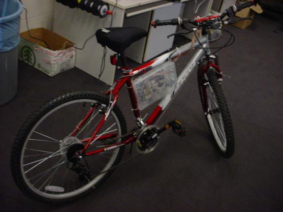
The bicycle is just a basic male bicycle with 26” tires and 21 gears. The bike also had a seat cushion which we used to hide the contact sensor.
User Interface Panel

The user interface panel is mounted on the handlebars for easy access and readability for the rider while the bike is in motion or stationary. The panel includes a 16X2 LCD, an LED, and 5 pushbutton switches. For the physical construction we used an old precision screwdriver case, soldered all the connections, and made the display more aesthetically pleasing by using a graphic design. The led is a normal red led that is then connected to a 330Ω resistor and then to an output port. The pushbuttons and the led all share a common ground to reduce the number of data lines to the interface and to fit on the 16 bits of the multi-conductor we purchased. The pushbuttons are pulled high with a 10 kΩ resistor. When the pushbutton is depressed, it pulls the signal low. In order for this button to work correctly it must be debounced. See the section on debouncing for more information. The pinouts for the User Interface Panel to the STK500 are listed in the pinout table.
Contact Sensor
This sensor is to determine if someone is sitting on the bike when it is locked. When someone sits on or touches the locked bicycle and sets of this sensor the alarm will sound. The contact sensor is located between the seat and the seat cushion. This pushbutton is pulled high and goes low when someone sits on the seat. Since we’re just looking for any sign of a low signal when the bike is locked, we do not need to debounce this sensor.
Velocity Meter
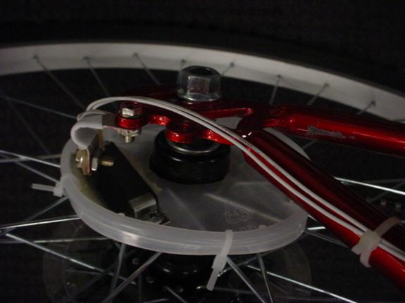
The velocity meter is a hall effect sensor that closes a switch when a magnet is in front of it. We use a relatively wide magnet close to the axle of the bicycle’s back tire to create a square wave. The sensor is pulled high and goes low when the magnet passes so we get a signal where the duty cycle is about 75% (we see the magnet 25% of the time). This sensor has been tested to the maximum that we could simulate in lab by setting the highest gear ratio and cranking as fast as possible. As a result, we know that the sensor works perfectly up to at least 45 mph. Since we saw no degradation in the signal quality we feel it’s same to assume it can go higher. The sensor itself is just a proximity device normally used in doors or windows for security systems. The magnet is a simple ceramic magnet. The key to getting a good signal was mounting the sensor and the magnet solidly and in close proximity to one another. Also, the substantial duty cycle achieved by mounting close to the axle helps to prevent missed signals or errors in the signal processing.
Audio Circuit
The audio circuit is a piezo transducer from radio shack. We send the signal through a 330 Ω resistor first to prevent pulling too much current from the board. We measured the current to confirm that it was in a normal range and the value was in tens of micro-amps. The piezo is designed to resonate at 2.5 kHz using a square wave, so we designed the code to run it at that frequency. Since we’re just creating an alarm that is supposed to be discomforting, we did not bother smoothing the signal or using any kind of filter. In general, the audio circuit is loud, obnoxious, and has even disturbed others working in the lab and caused them to come see what the noise is. That is exactly what this circuit was designed to do.
Wireless

Rather than use the wireless protocol that most groups employed, we opted for a cheaper and simpler approach. For a wireless remote we only needed to send a single bit to the state machine in the bike computer. Radiotronix offers a schematic to be used in conjunction with their 433 MHz receiver and transmitter pair for a simple pushbutton system. The schematic is included in the appendices. It would have been possible for us to simply sense if any signal was coming in at 433 MHz and send 433 our from the transmitter end. Unfortunately, this type of approach would not have allowed us to isolate ourselves from noise in this band, especially other projects using the exact same frequency. The Radiotrtonix schematic uses an HT-12E and HT-12D encoder/decoder pair to first send 8 address bits and then 2 data bits. The data bits are then decoded on the receiver end using a simple NAND gate circuit and sent directly to the STK500. We only used one of the data bits since we had no use yet for a second switch. If the project were continued you might be able to include something like a panic button using the additional hardware possibilities. We included all of the power suggestions from the schematic, using a 3V photo battery, the 5V from the STK500, and we also included the DC chokes and capacitors to reduce the effects of noise from the rest of the circuitry and to ensure that the antennae received enough power to transmit properly. The transmit circuit asks for some specific capacitor and inductor values but we substituted with the values available in lab. The inductors in particular are just hand wound wires, and since we haven’t been able to get in the 210 lab since we made them we’re unable to check their values. The antennae are just pieces of wire sticking out of the protoboard. The circuit performs well and gives up to 20 feet of range. The signal is not always clear and will be intermittent with lower signal quality. In order to overcome this error we have the software receive a signal and then block signals 5 seconds afterwards. This simple method effectively debounces the wireless. With regards to noise rejection, we have never received a false signal from another project in the lab. Since the rest of the circuit is just digital, we believe that the reduction in signal strength is due to the compromise in component values on our antennae.
Things We Tried that Did Not Work
We tried a variety of magnets and magnetic sensors. We found size made a difference in the signal sent by the magnet. Our largest magnet was sensed the furthest from the sensors we tested. Most of the sensors were very touchy so we chose the one that was the most reliable and very sensitive. Since All-Electronics didn’t offer any specs on the hardware by multiple sensors and choosing the best one was a very effective method.
Another area where we ran into trouble was in the mounting of the magnet to the bike wheel. We altered a wonton soup lid so it would fit over the axle of the bike. We then planned to epoxy the magnet to the lid. Although we bought multipurpose epoxy, either the material or the malleability of the lid may it immune to the epoxy. We then attempted to superglue the molded epoxy/magnet combo onto the lid, which was equally a failure. Finally, we used epoxy to connect the magnet to two metal wire organizers I had, and then screwed the magnet onto the lid. This method was very successful.
One problem that we ran into that was not associated with our design was in regards to the quality of Target’s merchandise. We bought a bike pump which inadvertently ate the pressure valve on the back tire. We had to then take the whole bike and tire apart and get a new pump (I never got the bike valve out of the pump, even with tools). Once we got the new pump we were able to get the bike ready for demo.
| Port A | Alarm | Port B | Buttons |
| Pin 0 | Piezo and LED | Pin 0 | |
| Pin 1 | Pin 1 | Contact Sensor | |
| Pin 2 | Pin 2 | ||
| Pin 3 | Pin 3 | Up button | |
| Pin 4 | Pin 4 | Down button | |
| Pin 5 | Pin 5 | Right button | |
| Pin 6 | Pin 6 | Left button | |
| Pin 7 | Pin 7 | OK button | |
| Port C | LCD | Port D | Sensor Input |
| Pin 0 | Pin 4 | Pin 0 | |
| Pin 1 | Pin 5 | Pin 1 | Magnetic Sensor |
| Pin 2 | Pin 6 | Pin 2 | Wireless Sensor |
| Pin 3 | Pin 3 | ||
| Pin 4 | Pin 11 | Pin 4 | |
| Pin 5 | Pin 12 | Pin 5 | |
| Pin 6 | Pin 13 | Pin 6 | |
| Pin 7 | Pin 14 | Pin 7 | |
| Gnd | Pins 1, 3 | ||
| Vcc | Pin 2 |
Results of the Design
Speed and execution
Timing is done using timer0 and timer2. Timer0 takes care of the task timing, whereas timer2 is used to generate a square waveform for sound generation. Both timers use compare match interrupt service routines to assure precise timing. The output compare registers are set such that timer0 interrupts every 100 milliseconds, whereas timer2 produces a 2.5 kHz square waveform.
Distance, velocity, and calories were computed into a single task that ran at least every 10 seconds. Another task that ran using timer0 involved turning on the square waveform to generate sound. This ran every 200 milliseconds and would produce a beep if the number of beeps set was a non-negative, non-zero integer.
Testing to see if the magnetic sensor was tripped was done at full speed to ensure that no pulses are missed.
The sound frequency is very accurate because the timer2 interrupt was used to generate the square waveform.
Accuracy
In terms of accuracy, the velocity calculated is very accurate at slow speeds, that is, when the pulse length is very long. This is because the accuracy depends on the function . Since t is inversely proportional to v, for small values of t, v changes dramatically. This is further intensified by the fact that t is discrete and is measured in whole milliseconds. The number of calories burned is directly related to the velocity, so inaccuracies in velocity are squared in the calories.
The distance measured is accurate to the circumference of the bicycle wheel, which in our demonstration is 81.75 inches. This is simply because there is one magnet and one magnetic sensor, which will be tripped once the bicycle has been rolled the circumference of the wheel. The accuracy can be greatly increased by adding more magnets to the bicycle wheel; however this level of accuracy is unnecessary because the distance is displayed in miles.
Safety
Since we are working with a bicycle we need to be concerned with the safety issues of the rider. We made sure that the electronics were all secured inside plastic enclosures to insulate the user from any electrical signals. All of the wires and enclosures were secured firmly to the vehicle to prevent anything from breaking loose while in motion. The bike itself for demo was prepared and is in good operating condition. The one major concern that we have is people attempting to view the display while they should be paying attention to the road. We mounted the interface panel at an angle to help the rider view it but they should still be cautious when choosing the moments to check their speed. Also, the calorie counter is designed to add up over time so you don’t have to check it until you’re done riding, and stopping along the way to check will not disturb the calorie counter.
Interference with Other People’s Design
Our bike computer is independent of other electronic systems with exception to the wireless. Our wireless is designed using an encoder/decoder pair that sends the address bits for the receiving end and then sends the data. This method should effectively isolate our systems on the 433 MHz band assuming that they are not using the same address. If multiple copies of our design were made, each bike would get a different address for the 256 different combinations. If you were going to mass produce the design, you would then go to a more commercial wireless system like the ones used for vehicles. Another area where interference might occur is with the bike manufacturers design. No part of our design caused any permanent damage to the bicycle itself. Everything was either screwed in using pre-existing holes, zip tied to the frame, or taped on. In order to make the contact sensor non-destructive, we added a seat cushion. Also, we removed the water bottle and water bottle holder from the bicycle to make room for the computer electronics. We don’t see any complications or interference with the bike manufacturers design.
Usability
The bike is designed to be as universal as possible. The system is designed for a 26” bicycle, but the code can be altered with the circumference of any bicycle, tricycle, or other moving vehicle. Also, the alarm on the bicycle is in conjunction with an LED, so the hearing impaired can also see that the alarm is going off. This visual back up would be more effective though if we used a high-power led or another more distracting system. The major requirement of our demo bike in particular is that the person be able to ride the bicycle and read English. The interface itself is very simple and intuitive. We simplified the interface from our initial specifications to simplify the interface. The wireless is also very easy, with just one button and audio feedback (3 beeps to lock and 2 beeps to unlock).
Conclusion
Our design worked as we had planned. We accomplished integrating the lcd, buttons, alarm, wireless, and the bicycle. If we were going to do it again we would probably build the custom board that would shrink the area the STK500 takes on the bicycle. Also, if we had more funding we would have included solenoids in the alarm system. That way if the alarm goes off, the solenoids would pull on the hand brakes and lock up the bicycle. In addition to money concerns this would also bring in a lot of power safety concerns as well. The wireless system could also be improved so that it worked more effectively when surrounded by the bicycle and the rest of the circuitry. A nicer LCD would also have been nice so we could simplify the state machine, display more information without going through menus, and also to make the display more visible to the rider. In general, we are very satisfied with our project and had a fun time creating the GoConn bicycle computer.
Intellectual Property Concerns
The only code that we reused in our design was the debouncer code from the ECE 476 website. We slightly modified this code to specifically see the rising edge of the button press. We did not use any code in the public domain. We did not reverse engineer any of the items in our design. We are not aware of any patent opportunities for our project since it has been done in subcomponents for bicycles in the past.
Legal Considerations
There are legal considerations that stem from any lawsuit associated with the safety of the device, see the safety section for clarification on safety concerns. There are also legal considerations with regard to intellectual property, see the intellectual property section for clarification on intellectual property concerns. Since this device uses wireless, there are also FCC regulations that must be met, see below.
FCC Regulations
Radiotronix designed their transmitter and receiver pair to comply with FCC standards. We are also using their wireless remote design in our project, which is also designed to conform with FCC standards. As the home built devices section states below “equipment authorization is not required for devices that are not marketed”. If you wish to group our wireless system in the “kit” category than the producers of that kit have already met the FCC regulations required of them. In addition, the home-built devices section states that “we are expected to employ good engineering practices”. In general we know that schematic we worked off of from Radiotronix should work up to around 100 feet. Since we used the capacitors and made hand wound inductors our circuit will not create as strong a signal as theirs and so our wireless only works up to around 20 feet. In terms of engineering this suggests that our circuit is then within regulations by being less powerful than the Radiotronix suggestion. As far as specific restrictions go for this band of communication, we found restrictions for the band 433.5-434.5 MHz (which includes our wireless at 433.9 MHz), but those specific restrictions apply to wireless communication for commercial shipping containers which is outside the scope of our project.
§ 15.23 Home-built devices.
(a) Equipment authorization is not required for devices that are not marketed, are not constructed from a kit, and are built in quantities of five or less for personal use.
(b) It is recognized that the individual builder of home-built equipment may not possess the means to perform the measurements for determining compliance with the regulations. In this case, the builder is expected to employ good engineering practices to meet the specified technical standards to the greatest extent practicable. The provisions of § 15.5 apply to this equipment. (page 767)
§ 15.240 Operation in the band 433.5–434.5 MHz.
(a) Operation under the provisions of this section is restricted to devices that use radio frequency energy to identify the contents of commercial shipping containers. Operations must be limited to commercial and industrial areas such as ports, rail terminals and warehouses. Two-way operation is permitted to interrogate and to load data into devices. Devices operated pursuant to the provisions of this section shall not be used for voice communications.
(This section goes on but is not necessary for our project).
(page 825-826)
FCC Regulations: 47 CFR Ch. I (10–1–05 Edition)
Appendices
Price Breakdown
| Mega32 | $8.00 |
| Transmitter RCT-433 Pin 1 | $4.00 |
| Receiver RCR-433 | $4.00 |
| STK500 | $15.00 |
| White board | $6.00 |
| LCD (16x2) | $8.00 |
| Data Bus | $0.75 |
| HT-12D | $1.69 |
| HT-12E | $1.69 |
| Pushbuttons | $1.50 |
| Magnet Sensor | $2.25 |
| Magnet | $0.25 |
| Misc. Passive Components | $1.00 |
| Total | $54.13 |
Specific Tasks
| Overall Design | Ryan and Jon |
| Interface Panel | Ryan |
| Velocity Sensor Construction | Ryan |
| Calorie Computation | Jon |
| Velocity Sensor | Ryan |
| Contact Sensor | Ryan |
| Velocity Computation | Ryan and Jon |
| Alarm | Ryan and Jon |
| General Coding Hierarchy | Jon |
| Coding Menus and Interface | Jon |
| Systems Integration | Ryan and Jon |
| Debugging | Ryan and Jon |
| Writeup | Ryan and Jon |
| Website | Jon |
Technical Information Used
Holtek HT-12E
Holtek HT-12D
Radiotronix RCR-433
Radiotronix RCT-433
Radiotronix Website: http://www.radiotronix.com/support/whitpap.asp
General Wireless Information
ECE 476 Website: http://instruct1.cit.cornell.edu/courses/ee476/
General Information on integrating subsystems and interface with STK500 and Mega32.
Code Listing
Thanks to Professor Land for instructing this course!