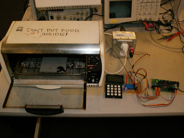
The Reflow Soldering Oven with LCD Display:
"Your Ordinary Toaster Oven on Crack"
By: Ko Ihara and Kashif Javed
Cornell ECE476, Spring 2006
WARNING: Solderpaste is highly toxic and 115/230 VAC is very dangerous!
Prevent any skin contact with solderpaste and never place food inside a reflow oven.
Take measures to prevent risks of lethal electrocution.
Contents
Introduction
Our project consists of making a reflow soldering device using a normal toaster
oven with a graphical LCD display for control and GUI. Soldering is an important
and difficult task for custom printed circuit board design especially for integrated
circuits that come as chip packages that are impossible to solder by hand. This
is particularly true for ball grid arrays (BGA) and small-pitch quad flat packs.
If one chooses to design a custom printed circuit board around these chips,
then the designer may wish to also purchase a stencil of the designed board
that would allow him to squeegee solderpaste precisely on the SMD pads. The
designer would then carefully place the components on the board, and heat the
solderpaste with a heat gun or a reflow soldering oven. The problem with soldering
ovens is that they are expensive and cost thousands of dollars. We have decided
to come up with a cheap and working solution to the problem by using a normal
toaster oven and controlling it through a microcontroller along with an LCD
display that guides the user through the soldering process and constantly provides
feedback on the state of the system while reflow soldering. The input to the
system would be via a conventional keypad and would consist of target temperature
point at specific times that the user would enter based on the solderpaste's
recommended tempearture profile. The system would interpolate the temperatures
for the in-between time intervals and follow the curve generated by the input.
The system would also fulfill the appropriate safety requirements and have the
capability of aborting the process in case of a mishap.
High Level Design
Rationale and source:
The source of the project was one of the team members Ko Ihara who as part of his M.Eng. project worked on designing a circuit board and came up with the idea of using a toaster
oven for reflow soldering. The project idea fully complies with the requirements of the course and the challenging part is coming up with a workable PID feedback control to make
the toaster oven follow the temperature curve and heat up or cool down at appropriate times. The Atmel mega32 chip is sufficient for this project as the speed of the chip and
the number of I/O pins suffices our needs. Another thing about the project is that it would benefit future students in the course since they would be able to solder boards with
less pain and high efficiency and safety.
Logical structure:
The project can be divided into three parts namely the LCD display, the oven control and lastly the temperature sensor inside the oven.
The following block diagram shows the logical structure of the system.
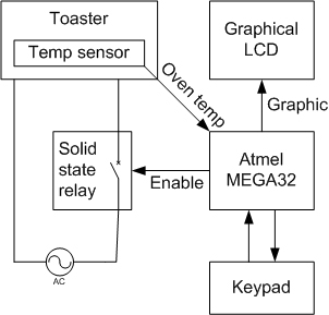
Figure 1: High-level system diagram
The microcontroller sends a digital signal to the solid state relay switch which controls the on/off state of the oven for appropriate heating and cooling.
The temperature sensor device inside the oven makes a voltage divider circuit in series with a resistor, the voltage signal is connected to the atmel mega32
ADC (analog to digital converter) input. The ADC output is used as a feedback by the program to measure temperature inside the oven and to control the relay
state. At the same time, the state of the system is updated in real time on the LCD and the user can see the progress. The keypad is used for input and the
LCD provides step by step instructions to the user during the input process. The oven control hardware containing the relay switch is inside a metal box
with the fuse circuit in place. It has the three pin plug connections for connecting the oven and the AC voltage supply. It also has harness plugs for
connecting the digital input to the microcontroller.
Hardware/Software tradeoffs:
The LCD RAM was emulated in software through a buffer as it was not possible to read it in real time from the RAM.
Relationship with Standards:
In the United States, the alternative-current electric power transmission was standardized by Westinghouse in the 1890s and the 115/230 VAC standard for
home appliance was adopted since the early 1900s. We could not find an IEEE standard that is specifically relevant to the power distribution method. As
for the FCC regulation, our project has nothing to do with that.
Trademarks and Patents:
There are several patents associated with the design of a solder reflow oven, such as U.S. patent 6794616 by Lakhi Nandlal Goenka in 2004.
However, these are IPs are specific to the detailed design of the oven, not the general concept of reflow soldering itself.
There are several companies like Harotec/ SAB and Novastar that make reflow ovens but these are expensive devices targeting high-end commercial
markets where as our project is intended towards hobbyists and students who can not afford these products.
Program/Hardware Design
HARDWARE:
MCU:
The microcontroller that we used is an Atmel MEGA32 chip. It was soldered on the custom prototype board provided for this course.
We are using all the four ports A-D for I/O and therefore all of those were soldered on the board. The MCU is programmed via the STK 500 board.
LCD and Keypad:
The keypad used is the same as for previous labs. It is connected to PORT C
and is debounced to nullify the vibrating effect of the buttons due to their
mechanical nature. The LCD used for the project is a 128 x 64 pixel graphical
display model manufactured by Crystalfontz America, Inc. It has a 20 pin interface
with a 5.0 V requirement for logic and 8.0 V requirement for the LCD display.
The LCD is soldered on a prototype board along with the keypad. It is connected
to PORT B and PORT D (6 pins out of 8) of the mcu. Both ports are used as output
providing the necessary signals to the LCD for the control. The LCD has a KS0108B
controller built in it and is divided into two columns of 64 x 64 pixels with
a column select pin to switch between them. Each column is further divided into
8 pages with each page consisting of 8 rows of 64 pixels each. The LCD RAM that
corresponds to 128 x 64 pixels or 1K bytes is addressed in a way that all 8
rows belonging to the same column (y axis, not to be confused with the two columns
mentioned above) in a page can be read or written at a time. The pixels are
set on high logic and cleared on low. The set p and hold times for addresses
or data were of the order of nanosecond which means that the LCD interaction
could be easily done in real time. The LCD was powered through a voltage divider
circuit using the Maxim ICL7660CPA reverse voltage generator which is also soldered
on the prototype board.
Figure 2: Keypad configuration
Relay Box:
The relay switch used for the project was sampled from Omron Electronics and has the maximum rating of 75 A at 24 to 240 AC which is more than enough for a normal toaster oven.
The relay switch was placed in a heat sink metal box with three input plug connectors mounted inside to connect the toaster oven and the AC power supply.
The digital input was connected via harness plugs that were drilled into the box. The signal for the solid state relay switch was given through PORTD5 via the prototype board.
Thermistor:
The temperature device used was an NTC thermistor with temperature range from -40 to 300 Celsius. The device was placed inside the oven and connected to the voltage divider
circuit on the prototype board. The thermistor was connected in series with a 2K ohm resistor and was powered through an LM711 op amp which acted as a buffer or voltage
forwarding device. The variable voltage output from the circuit is fed to the mega32 via pin A0 that goes into the ADC on the chip.
The system is fairly easy to replicate, however care must be taken when connecting the various signals especially the relay box as it requires dealing with live 240 AC supply and must be done by trained personnel.
Pleases refer to appendix B and the pictures for an illustration of our hardware design. For further assistance, refer to the data sheets of the various components in appendix E.
| Port | Function |
| PORTA0 | Thermistor voltage |
Table 1: MEGA32 PORTA Connections
| Port | Function |
| PORTB0 | DB0 (LCD) |
| PORTB1 | DB1 (LCD) |
| PORTB2 | DB2 (LCD) |
| PORTB3 | DB3 (LCD) |
| PORTB4 | DB4 (LCD) |
| PORTB5 | DB5 (LCD) |
| PORTB6 | DB6 (LCD) |
| PORTB7 | DB7 (LCD) |
Table 2: MEGA32 PORTB Connections
| Port | Function |
| PORTC0 | Pin 1 (Keypad) |
| PORTC1 | Pin 2 (Keypad) |
| PORTC2 | Pin 3 (Keypad) |
| PORTC3 | Pin 4 (Keypad) |
| PORTC4 | Pin 5 (Keypad) |
| PORTC5 | Pin 6 (Keypad) |
| PORTC6 | Pin 7 (Keypad) |
| PORTC7 | Pin 8 (Keypad) |
Table 3: MEGA32 PORTC Connections
| Port | Function |
| PORTD0 | CS1 (LCD) |
| PORTD1 | CS2 (LCD) |
| PORTD2 | Reset (LCD) |
| PORTD3 | R/~W (LCD) |
| PORTD4 | D/~I (LCD) |
| PORTD5 | Relay signal |
| PORTD7 | Enable (LCD) |
Table 4: MEGA32 PORTD Connections
PROGRAM:
The software design of the system can be divided into three main categories. LCD display functionality, control flow of the system and PID control.
LCD Display Functionality:
The LCD functionality is one of the most important features of our system since all the interaction between the user and the soldering system is performed via the LCD. The main function for the LCD display is the setpixelxy() procedure which takes in three arguments row, column and a flag value. The flag determines if the pixel at position row (0-63 vertically) column (0-127 horizontally) is set or cleared with 1 being set and 0 being cleared. The LCD as mentioned before doesn't allow a single pixel to be written and only allows a byte to be written in the corresponding page. For this reason, the LCD RAM has to be read first and the pixel position in that byte has to be updated with the new setting. We tried reading the LCD on the fly but it was not accomplished and therefore an LCD buffer of the same size as the RAM (1K) was created in the mcu's eprom memory. This buffer in the software was used as a virtual RAM for the LCD which was updated and read whenever the display was updated. The next step was to implement alphanumeric characters for displaying data. Bitmaps were created for characters from 0-Z and also for some special characters like space, period hyphen etc. These bitmaps are displayed on the LCD using wrappers like putbyte() and putchars() which set the corresponding pixels.
Another function was the drawline() function which takes in four parameters x1, y1 ,x2,y2 and draws a line between them. This function was taken from the video code provided by Professor Land for lab 4. The following graph shows our LCD display model.
Figure 3: Graphical LCD display format
The x-axis is the time axis with a resolution of 1 pixel per 3 seconds. The y-axis shows the temperature in Celsius scale with 1 pixel corresponding to 5 degree Celsius change. The bottom line is the area where the instruction and feedback to the user is displayed. Each character is 5 x 4 pixels wide and is readable to the naked eye.
The maximum time for our system is set at 340 seconds meaning that it can handle 340 temperature points and can run for approximately three and a half seconds with maximum temperature of 250 Celsius. These limits were determined by analyzing a standard reflow curve. The user input is taken in an array of 340 elements with the index corresponding to the time and the value corresponding to the temperature at that time. A function interpolate() was written that scans the array and linearly interpolates the empty slots between target points.
Other LCD functions include:
clear() - clears the display
drawgraph() - draws the target curve
cleargraph() - clears the target curve but marks target points at 30 second intervals for comparison with the actual curve updated every second as reflow continues.
Control Flow:
The main function of the program calls the initialize() routine which sets up the display of the LCD, sets up the various registers for timer interrupts and ADC, Sets up the ports and prompts the user for input via the LCD. The main function then loops infinitely calling the keyscan function every 30 millisecond for user input on the keypad and the heat() function every seconds which controls the reflow soldering system from the time a prt is entered till it has been soldered.
The program starts in defaultmode which is a pre-programmed mode with a standard temperature curve as shown below.
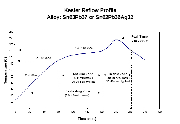
Figure 4: The recommended temperature profile for Kester solderpaste
The user is prompted for input by displaying appropriate message on the LCD. If the user wants to use the default curve, he/she can press the # key on the keypad which corresponds to "yes". The keyscan code upon input would call the button handler which implements part of the state machine for the system. The system would go into the pre-heat mode and the default curve would be displayed. The heat function which implements the rest of the state machine would notice the mode set to preheat and PIND 5 would be set high to trigger the relay which in turn switches on the oven. This routine is called every second and converts the ADC output into temperature using the calibration table hard coded in the flash memory. The calibration procedure for the NTC thermistor is described in a later section. The procedure keeps on polling the temperature till it reaches the desired starting temperature for time input 0. Once preheating is complete, cleargraph() is called, the mode is set to ready and the user is prompted to insert the part and press "yes". Once the user presses "yes", The mode is set to reflow and the heat() routine calls the PID() routine which implements the feedback control system to control the relay. At the same time the, the current state of the system is shown on the graph which is updated every second. Once the maximum time is reached, the oven control is disabled and the system is put into the cool down mode. The system is allowed to cool till it reaches a safe temperature, the state is set to done, and the user is prompted to remove the part and press "yes". The system is re-initialized in the done state and made ready for the next task.
If the user had chosen not to use the default mode, then the system would have entered the program2 state. This is the mode for entering temperature input and assumes that the first input is for time 0. The user would enter the temperature desired and press yes. This temperature is added to the input array, interpolated and the target curve is updated. The next state is program 3 where he is asked for further input, if yes he is taken into state program1 where he can enter the time for the next temperature input. From program1 he is taken into program2 which takes in temperature for the last time and goes into program 3. This continues till the user presses "no" (* key on the keypad) in program3 and the mode is changed to preheat to start the reflow mechanism as described above. The user can press the abort key (A key on the keypad) at anytime to abort the procedure. The abort mode disables the control and takes the system into cool down mode.
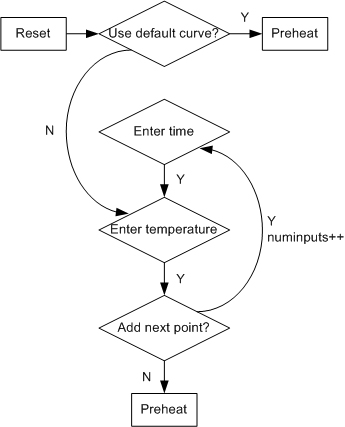
Figure 5: program flow diagram - target programming mode
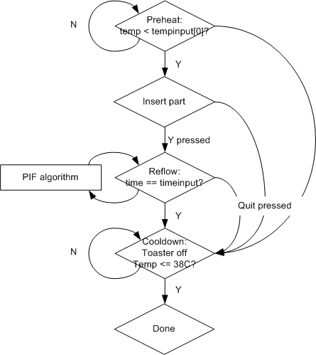
Figure 6: program flow diagram - heat mode
Thermistor Calibration:
We took the resistance vs. temperature data from the BC 2322-633-83303
thermistor datasheet, and converted all resistance values into corresponding analog voltage, when
the thermistor is placed in a two-resistor voltage divider circuit with a 2kOhm resistor.
The voltage vs. temperature information was curve-fitted in Microsoft Excel by a 5-order polynomial
fit. The temperature equation was estimated to be
Temp = -1.3722*V^5 + 17.067*V^4 - 80.523*V^3 + 182.7*V^2 + 235.79*V^2 + 272
Using this equation, every corresponding temperature to analog-to-digital converted count values
between 0 and 1,023 were calculated and stored in MEGA32's flash memory.
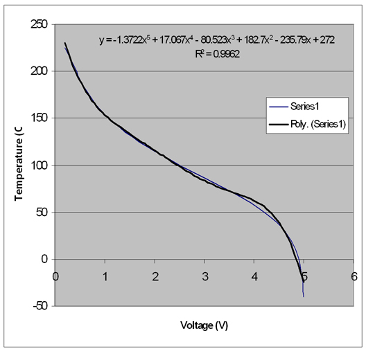
Figure 7: Curve-fitted data for the NTC thermistor
Proportional-Derivative-Future-Integral (PD+F) control algorithm:
The bang-bang control in the reflow mode failed to follow the curve accurately, so a sophisticated control
algorithm was necessary.
For the control of the toaster oven, we decided to use a modified proportional-derivative control algorithm
that we call "PD+F" algorithm. Because the time-based temperature target and the most recent
d(temp)/d(time) slope is known, we can estimate the future errors by extrapolating two most recently measured
temperatures. Our PWM signal was configured to have a constant period of 1 second, with a variable duty cycle
calculated form our PD+F algorithm, shown below:
Duty cycle[n] = Kp*proportional[n] + Kd*derivative[n] + Kf*futureintegral[n], where
proportional[n] = target[n] - temp[n],
derivative[n] = proportional[n] - proportaional[n-1], and
futureintegral[n] = sum of (target[n+i] - (temp+i*(temp[n]-temp[n-1]))) * (size-i)/size, for i=1 to size
The last (size-i)/size is for linear-deemphasis of the future error estimation: more emphasis is placed on
the error estimation in the near future.
Please refer to appendix A for a commented listing of the code. For further assistance, refer to the data sheets of the various components in appendix E.
Results of the Design
Speed:
The system worked at our desired speed. The LCD display worked in real time without any noticeable delays. The relay triggering was fast. Since the system was updated every second, the latency of the key scanner and the PID control was hidden because mega32 at 16MHz frequency was able to perform all the instructions without missing any interrupts.
Accuracy:
Given the experimental conditions and the hardware we had, the accuracy was good enough. The system was able to follow the target curve within a 10 degree Celsius locus. We tested the system by putting solder inside the oven and were able to melt the solder in a 210-240 degree Celsius range.
Safety:
Proper care was taken in building the system. The relay switch was place inside a heat sink metal box to ensure heat dissipation. Thermal paste was layered between the box and the relay. The box contains a fuse holder to regulate the current provided to the system. All the connector plugs were inserted on plastic insulated washers avoid short circuiting. The relay box was tested in the presence of Professor Land before plugging to the toaster.
Interference:
The system did not interfere with any other project and no complaints were made against the system by any group.
Usability:
The LCD display makes our system highly interactive and easy to use. The keypad was debounced to ensure correct input and appropriate error messages were displayed on erroneous input.
Conclusions
Analysis:
We are happy with the performance of our system. One of the problems we faced was cooling the system i.e. if the future target points show a decrease in temperature at a steep gradient, then the actual curve would be slightly off. This is due to the inertia of the oven. The heating coil retains the heat for a while even though the oven is off. This causes a slower decay in temperature. Similarly, a steep rise in temperature is also not readily achievable due to the heating limitation of the toaster oven.
One of our future advancement would be to add a cooling system to the project. We can add fans that are triggered if the current temperature is higher then the target temperature. Another idea is to use a fan to blow hot air in the oven instead of using the heating coil. This way the same blower can be used to heat and cool the system by changing the temperature of the air blown in.
The toaster oven used was an old one and had an inaccurate temperature controller inside which caused it to shutdown sometime even though the temperature was below the specification on the oven. This hindered our project a little particularly in heating up the oven. But this can be resolved by using a better quality oven.
Intellectual property considerations:
We re-used the video_line code from lab4 and a sample code for the LCD was used as reference for our LCD functionality. No reverse-engineering was done and neither did we have to sign an NDC form for sampling any of our parts. Our design is simple and the product we present is cheaper then its rivals in the market, therefore there could be patent opportunity for our product.
Ethical considerations:
We believe that our project conforms to the ethical considerations and is consistent with the IEEE code of ethics as explained below.
- to accept responsibility in making decisions consistent with the safety, health and welfare of the public, and to disclose promptly factors that might endanger the public or the environment;
We took all the necessary precautions in ensuring public health and safety. It has to be understood that our project is designed for people who understand its usage and are trained in handling electrical devices.
- to avoid real or perceived conflicts of interest whenever possible, and to disclose them to affected parties when they do exist;
We did not face any conflicts of interest.
- to be honest and realistic in stating claims or estimates based on available data;
All our results and claims are tru to the best of our knowledge.
- to reject bribery in all its forms;
We were not offered any bribery.
- to improve the understanding of technology, its appropriate application, and potential consequences;
The project is a step in using technology and applying it to come up with a system which has a better cost/benefit ratio.
- to maintain and improve our technical competence and to undertake technological tasks for others only if qualified by training or experience, or after full disclosure of pertinent limitations;
The project was a good learning experience. It improved our capability as engineers and the tasks undertaken were certainly not beyond our cappabilites which can be proven since it was completed.
- to seek, accept, and offer honest criticism of technical work, to acknowledge and correct errors, and to credit properly the contributions of others;
We are fully open to criticism and hope that any external input would help us in correcting our mistakes and improving our project and any future work that we may carry out. We have acknowledged and credited the people who helped us by contributing their expertise or hardware to our project.
- to treat fairly all persons regardless of such factors as race, religion, gender, disability, age, or national origin;
We were fair in our treatment of individuals during the course of this project.
- to avoid injuring others, their property, reputation, or employment by false or malicious action;
The project did not cause any injuries or damage to any person or property.
- to assist colleagues and co-workers in their professional development and to support them in following this code of ethics.
We are willing to offer help anybody who seeks it and this project is an example for future students to use and learn from.
Legal Considerations: Our project did not have any FCC regulations associated with and there were no legal considerations necessary in its implementation.
Appendix A: Program Code
toaster.c
#include <Mega32.h>
#include <delay.h>
#include <stdio.h>
#include <math.h>
#include <stdlib.h>
#include <string.h> #define begin {
#define end }
#define map_size 128*64/8
#define max_time 340
#define base_temp 0
#define room_temp 40
//Timing
#define t1 30
#define t2 1000
//Keypads
#define maxkeys 13 //characters
#define no 11
#define yes 12
#define quit 13
#define ERR_SIZE 11
//Debouncing
#define release 1
#define debounce 2
#define stillPressed 3
#define debounceRelease 4
//Program modes
#define program1 0
#define program2 1
#define program3 2
#define preheat 3
#define ready 4
#define reflow 5
#define cooldown 6
#define done 7
#define abort 8
#define usedefault 9
void intialize();
void keyScan();
void buttonHandle();
void heat();
void pid();
eeprom int tempinput[max_time];
int timeinput, temp,timer,prevtemp=0;
char numinputs;
int err[ERR_SIZE];
char lcdmap[map_size];
int time1, time2, time3;
unsigned char key, butnum, maybe, scanState; //Non-debounced key press
int mode, prevmode;
char digits[10], index, str[32];
unsigned int number = 0;
#include "flash.c"
#include "lcd.c"
//===============================================
//timer 0 compare ISR
interrupt [TIM0_COMP] void timer0_compare(void)
{
//Decrement the three times if they are not already zero
if (time1>0) --time1;
if ((time2>0) && (mode==preheat || mode==ready ||mode==reflow||mode==abort||mode==cooldown))
--time2;
}
//===============================================
void interpolate(void)
{
int i=1,j,k=0;
int lastN=0;
float grad;
while(i<max_time)
{
if(tempinput[i] != 0)
{
grad = ((int)(tempinput[i]-tempinput[lastN]))/(((float)i-(float)lastN));
for(j=lastN+1,k=1; j<i ; j++,k++) tempinput[j] = (k)*grad + tempinput[lastN];
lastN = i;
}
i++;
}
}
//===============================================
int main (void)
{
intialize();
while(1)
{
if(time1 <= 0) keyScan();
if(time2 <= 0) heat();
}
}
//===============================================
void intialize()
{
int i=0, j=0;
for(i=0;i<map_size;i++) lcdmap[i]=0;
for(i=0;i<max_time;i++) tempinput[i]=0;
clear();
pixelxy(10,13,1); pixelxy(20,13,1); pixelxy(30,13,1); pixelxy(40,13,1);
pixelxy(51,34,1); pixelxy(51,54,1); pixelxy(51,74,1); pixelxy(51,94,1); pixelxy(51,114,1);
drawline(0,14,49,14);
drawline(50,14,50,127);
//Temperature labels
sprintf(str,"200"); putstr(8,0,str);
sprintf(str,"150"); putstr(18,0,str);
sprintf(str,"100"); putstr(28,0,str);
sprintf(str," 50"); putstr(38,0,str);
//Time labels
sprintf(str,"60"); putstr(53,30,str);
sprintf(str,"120"); putstr(53,48,str);
sprintf(str,"180"); putstr(53,68,str);
sprintf(str,"240"); putstr(53,88,str);
sprintf(str,"300"); putstr(53,108,str);
//default values
tempinput[0]=90; //Or room temp
tempinput[90]=150;
tempinput[180]=180;
//tempinput[210]=225;
tempinput[240]=225;
tempinput[270]=225;
timeinput=270;
numinputs=5;
interpolate();
scanState = release;
time1 = t1;
time2 = t2;
time3 = t3;
mode=usedefault;
sprintf(str,"Y:USE DEFAULT CURVE N:PROGRAM");
message(str);
for(i = 0; i < 10; i++) digits[i] = 0;
index = 0;
//set up timer 0
TIMSK = 2; //turn on timer 0 cmp match ISR
OCR0 = 250; //set the compare re to 250 time ticks
//prescalar to 64 and turn on clear-on-match
TCCR0=0b00001011;
DDRA = 0x00; //PORTA input
//adc stuff
ADMUX = 0b01100000;
//enable ADC and set prescaler to 1/128*16MHz=125,000
//and clear interupt enable
//and start a conversion
ADCSR = 0b11000111;
//crank up the ISRs
#asm
sei
#endasm
}
//===============================================
//Task subroutines
//keyScan: scan the key
void keyScan()
{
//Reset timeout counter
time1=t1;
//get lower nibble
DDRC = 0x0f;
PORTC = 0xf0;
delay_us(5);
key = PINC;
//get upper nibble
DDRC = 0xf0;
PORTC = 0x0f;
delay_us(5);
key = key | PINC;
//find matching keycode in keytbl
if (key != 0xff)
{
for (butnum=0; butnum<maxkeys; butnum++)
{
if (keytbl[butnum]==key) break;
}
if (butnum==maxkeys) butnum=0;
else butnum++; //adjust by one to make range 1-16
}
else butnum=0;
//debouncing finite state machine
switch(scanState)
{
case release:
if(0x00==butnum)
scanState=release;
else
{
scanState=debounce;
maybe=butnum;
}
break;
case debounce:
if(maybe==butnum)
{
scanState=stillPressed;
buttonHandle();
}
else
scanState=release;
break;
case stillPressed:
if(butnum==maybe)
scanState=stillPressed;
else
scanState=debounceRelease;
break;
case debounceRelease:
if(butnum==maybe)
scanState=stillPressed;
else
scanState=release;
break;
}
}
//===============================================
void buttonHandle()
{
int i;
if((butnum<=10) && (index<10))
{
digits[index++] = butnum - 1 + '0';
digits[index] = NULL;
number=atoi(digits);
if(mode == program1) sprintf(str,"ENTER TIME %d:%d",numinputs,number);
if(mode == program2) sprintf(str,"ENTER TEMPERATURE %d:%dC",numinputs,number);
message(str);
}
if(butnum == no)
{
for(i = 0; i < 10; i++) digits[i] = 0;
number=atoi(digits);
index = 0;
if(mode == 9/*usedefault*/)
{
//PORTA=0x00;
for(i=0;i<max_time;i++) tempinput[i]=0;
timeinput=0;
numinputs=0;
sprintf(str,"ENTER TEMPERATURE:");
mode = program2;
}
else if(mode == program1) sprintf(str,"ENTER TIME %d:%d",numinputs,number);
else if(mode == program2) sprintf(str,"ENTER TEMPERATURE %d:%dC",numinputs,number);
else if(mode == program3)
{
sprintf(str,"PROGRAMMED CURVE:PREHEATING...%dC",temp);
mode = preheat;
}
message(str);
}
if(butnum == yes)
{
if(mode==usedefault)
{
//timeinput=300;
numinputs=6;
drawgraph();
sprintf(str,"DEFAULT CURVE:PREHEATING...%dC",temp);
message(str);
mode = preheat;
}
else if(mode==program1)
{
if(number <= timeinput){
for(i = 0; i < 10; i++) digits[i] = 0;
index = 0;
sprintf(str,"ERROR:MUST BE MORE THAN %d!",timeinput);
message(str);
}
else if(number > max_time){
for(i = 0; i < 10; i++) digits[i] = 0;
index = 0;
sprintf(str,"ERROR:MUST BE LESS THAN %3d!",max_time);
message(str);
}
else{
timeinput = number;
mode = program2;
for(i = 0; i < 10; i++) digits[i] = 0;
number=atoi(digits);
index = 0;
sprintf(str,"ENTER TEMPERATURE %d:", numinputs);
message(str);
}
}
else if(mode==program2)
{
if(number > 250){
for(i = 0; i < 10; i++) digits[i] = 0;
index = 0;
sprintf(str,"ERROR:MUST BE 250C OR LESS!");
message(str);
}
else{
tempinput[timeinput] = number;
mode = program3;
numinputs++;
interpolate();
drawgraph();
sprintf(str,"Y:ADD NEXT POINT N:NO MORE",timeinput,number);
message(str);
}
}
else if(mode==program3)
{
mode = program1;
for(i = 0; i < 10; i++) digits[i] = 0;
number=atoi(digits);
index = 0;
sprintf(str,"ENTER TIME %d:", numinputs);
message(str);
}
else if(mode==ready)
{
timer=0;
ICR1H = 0xf4;
ICR1L = 0x24;
DDRD = 0xff; //PORTD output
TCCR1A = 0b10001110;
TCCR1B = 0b00011100;
OCR1A = 0x0000;
mode=reflow;
}
else if(mode==done)
{
intialize();
}
}
if(butnum==quit)
{
//PORTD.7^=1;
OCR1A = 0;
mode=abort;
sprintf(str,"ABORTING...");
message(str);
}
}
//===============================================
void heat()
{
int adch, adcl;
adcl = ADCL; //Read ADCL first; causes ADC block
adch = ADCH; //Read ADCH; remove the ADC block
adch = adch<<2; //Bits 9:2
adcl = adcl>>6; //Bits 1:0
adch |= adcl; //Index for conversion table
time2 = t2;
prevtemp = temp;
temp = temperature[adch];
ADCSR.6=1;
timer++;
if(mode == preheat){
if (temp < tempinput[0]){
PORTD.5=1;//PORTA = 0x00;// heater on
sprintf(str,"PREHEATING...WAIT:%d C",temp);
message(str);
}
else {
PORTD.5=0;
mode = ready;
cleargraph();
sprintf(str,"READY. INSERT PART AND PRESS Y");
message(str);
}
}
else if(mode==reflow) {
if(timer==timeinput) {
//heater off
//PORTD.7=0;
OCR1A = 0x0000;
mode=cooldown;
sprintf(str,"COOLING DOWN... TEMP:%3dC",temp);
message(str);
}
else{
pid();
//OCR1A = 0x0000;
//if(temp < tempinput[timer])PORTD.5=1;
//else PORTD.5=0;
sprintf(str,"TIME:%3d TMP:%3dC CRV-TMP:%3dC",timer,temp,tempinput[timer]);
message(str);
setcurvepixel(temp,timer);
}
}
else if(mode==cooldown) {
if(temp<=room_temp) {
mode=done;
sprintf(str,"DONE COOLING.REMOVE PART-PRESS Y");
}
else sprintf(str,"COOLING DOWN... TEMP:%3dC",temp);
message(str);
}
else if(mode==abort){
//PORTD.7=0;
// OCR1A = 0x0000;
mode=cooldown;
}
}
void pid()
{
long Kp = 12500; //6250; //Proportional constant
long Kd = 5000;//5000; //Derivative constant
long Ki = 0; //Integral constant
long Kf = 2000; //Future integral error;
long proportional, derivative, integral, futureintegral;
long dutycycle;
char i;
//Keep record of past 10 errors
for(i = ERR_SIZE-1; i > 0; i--){
err[i] = err[i-1];
}
//Error now
err[0] = tempinput[timer] - temp;
proportional = err[0];
derivative = err[0] - err[1];
//Past 10 errors
//integral = 0;
//for(i = 1; i < ERR_SIZE; i++) integral += err[i];
//Look into 10 future errors
futureintegral = 0;
if(timer < (max_time-ERR_SIZE))
//for(i = 1; i < ERR_SIZE*2; i++) futureintegral += tempinput[timer+i] - (temp+i*(temp-prevtemp);
for(i = 1; i < ERR_SIZE; i++) futureintegral += (tempinput[timer+i] - (temp+i*(temp-prevtemp)))
* (ERR_SIZE-i)/(ERR_SIZE);
dutycycle = Kp * proportional + Kd * derivative + Ki * integral + Kf * futureintegral;
if(dutycycle > 62500) dutycycle = 62500;
if(dutycycle < 0 || timer >= timeinput) dutycycle = 0;
OCR1A = dutycycle;
}
flash.c
flash unsigned char smallbitmap[42][4]={
//0
0b00000000,
0b00011111,
0b00010001,
0b00011111,
//1
0b00000000,
0b00000000,
0b00011111,
0b00000000,
//2
0b00000000,
0b00011101,
0b00010101,
0b00010111,
//3
0b00000000,
0b00010101,
0b00010101,
0b00011111,
//4
0b00000000,
0b00000111,
0b00000100,
0b00011111,
//5
0b00000000,
0b00010111,
0b00010101,
0b00011101,
//6
0b00000000,
0b00011111,
0b00010100,
0b00011100,
//7
0b00000000,
0b00000001,
0b00000001,
0b00011111,
//8
0b00000000,
0b00011111,
0b00010101,
0b00011111,
//9
0b00000000,
0b00000111,
0b00000101,
0b00011111,
//:
0b00000000,
0b00000000,
0b00001010,
0b00000000,
//-
0b00000000,
0b00000100,
0b00000100,
0b00000100,
//!
0b00000000,
0b00000000,
0b00010111,
0b00000000,
//.
0b00000000,
0b00000000,
0b00010000,
0b00000000,
//,
0b00000000,
0b00000000,
0b00011000,
0b00000000,
//space
0b00000000,
0b00000000,
0b00000000,
0b00000000,
//A
0b00000000,
0b00011111,
0b00000101,
0b00011111,
//B
0b00000000,
0b00011111,
0b00010101,
0b00001010,
//C
0b00000000,
0b00001110,
0b00010001,
0b00010001,
//D
0b00000000,
0b00011111,
0b00010001,
0b00001110,
//E
0b00000000,
0b00011111,
0b00010101,
0b00010101,
//F
0b00000000,
0b00011111,
0b00000101,
0b00000101,
//G
0b00000000,
0b00001110,
0b00010001,
0b00011101,
//H
0b00000000,
0b00011111,
0b00000100,
0b00011111,
//I
0b00000000,
0b00010001,
0b00011111,
0b00010001,
//J
0b00000000,
0b00010000,
0b00010001,
0b00001111,
//K
0b00000000,
0b00011111,
0b00000100,
0b00011011,
//L
0b00000000,
0b00011111,
0b00010000,
0b00010000,
//M
0b00000000,
0b00011111,
0b00000010,
0b00011111,
//N
0b00000000,
0b00011111,
0b00000001,
0b00011110,
//O
0b00000000,
0b00011111,
0b00010001,
0b00011111,
//P
0b00000000,
0b00011111,
0b00000101,
0b00000111,
//Q
0b00000000,
0b00000111,
0b00000101,
0b00011111,
//R
0b00000000,
0b00011111,
0b00000101,
0b00011011,
//S
0b00000000,
0b00010111,
0b00010101,
0b00011101,
//T
0b00000000,
0b00000001,
0b00011111,
0b00000001,
//U
0b00000000,
0b00011111,
0b00010000,
0b00011111,
//V
0b00000000,
0b00001111,
0b00010000,
0b00001111,
//W
0b00000000,
0b00011111,
0b00001000,
0b00011111,
//X
0b00000000,
0b00011011,
0b00000100,
0b00011011,
//Y
0b00000000,
0b00000011,
0b00011100,
0b00000011,
//Z
0b00000000,
0b00011001,
0b00010101,
0b00010011
};
flash int temperature[1024] = {
272, 271, 270, 269,
267, 266, 265, 264,
263, 262, 261, 260,
259, 258, 257, 256,
255, 254, 253, 252,
251, 250, 249, 248,
247, 246, 245, 244,
243, 242, 241, 240,
239, 238, 238, 237,
236, 235, 234, 233,
232, 231, 231, 230,
229, 228, 227, 227,
226, 225, 224, 223,
223, 222, 221, 220,
220, 219, 218, 217,
217, 216, 215, 215,
214, 213, 212, 212,
211, 210, 210, 209,
208, 208, 207, 206,
206, 205, 205, 204,
203, 203, 202, 202,
201, 200, 200, 199,
199, 198, 197, 197,
196, 196, 195, 195,
194, 194, 193, 193,
192, 191, 191, 190,
190, 189, 189, 188,
188, 187, 187, 186,
186, 186, 185, 185,
184, 184, 183, 183,
182, 182, 181, 181,
181, 180, 180, 179,
179, 178, 178, 178,
177, 177, 176, 176,
176, 175, 175, 174,
174, 174, 173, 173,
172, 172, 172, 171,
171, 171, 170, 170,
170, 169, 169, 169,
168, 168, 168, 167,
167, 167, 166, 166,
166, 165, 165, 165,
164, 164, 164, 163,
163, 163, 162, 162,
162, 162, 161, 161,
161, 160, 160, 160,
160, 159, 159, 159,
158, 158, 158, 158,
157, 157, 157, 157,
156, 156, 156, 156,
155, 155, 155, 155,
154, 154, 154, 154,
153, 153, 153, 153,
152, 152, 152, 152,
151, 151, 151, 151,
150, 150, 150, 150,
150, 149, 149, 149,
149, 148, 148, 148,
148, 148, 147, 147,
147, 147, 147, 146,
146, 146, 146, 146,
145, 145, 145, 145,
145, 144, 144, 144,
144, 144, 143, 143,
143, 143, 143, 142,
142, 142, 142, 142,
141, 141, 141, 141,
141, 140, 140, 140,
140, 140, 140, 139,
139, 139, 139, 139,
138, 138, 138, 138,
138, 138, 137, 137,
137, 137, 137, 136,
136, 136, 136, 136,
136, 135, 135, 135,
135, 135, 135, 134,
134, 134, 134, 134,
133, 133, 133, 133,
133, 133, 132, 132,
132, 132, 132, 132,
131, 131, 131, 131,
131, 131, 130, 130,
130, 130, 130, 130,
129, 129, 129, 129,
129, 129, 128, 128,
128, 128, 128, 127,
127, 127, 127, 127,
127, 126, 126, 126,
126, 126, 126, 125,
125, 125, 125, 125,
125, 124, 124, 124,
124, 124, 124, 123,
123, 123, 123, 123,
123, 122, 122, 122,
122, 122, 122, 121,
121, 121, 121, 121,
121, 120, 120, 120,
120, 120, 120, 119,
119, 119, 119, 119,
119, 118, 118, 118,
118, 118, 117, 117,
117, 117, 117, 117,
116, 116, 116, 116,
116, 116, 115, 115,
115, 115, 115, 115,
114, 114, 114, 114,
114, 114, 113, 113,
113, 113, 113, 113,
112, 112, 112, 112,
112, 112, 111, 111,
111, 111, 111, 110,
110, 110, 110, 110,
110, 109, 109, 109,
109, 109, 109, 108,
108, 108, 108, 108,
108, 107, 107, 107,
107, 107, 107, 106,
106, 106, 106, 106,
106, 105, 105, 105,
105, 105, 105, 104,
104, 104, 104, 104,
104, 103, 103, 103,
103, 103, 103, 102,
102, 102, 102, 102,
102, 101, 101, 101,
101, 101, 101, 100,
100, 100, 100, 100,
100, 99, 99, 99,
99, 99, 99, 98,
98, 98, 98, 98,
98, 97, 97, 97,
97, 97, 97, 96,
96, 96, 96, 96,
96, 96, 95, 95,
95, 95, 95, 95,
94, 94, 94, 94,
94, 94, 93, 93,
93, 93, 93, 93,
93, 92, 92, 92,
92, 92, 92, 92,
91, 91, 91, 91,
91, 91, 90, 90,
90, 90, 90, 90,
90, 89, 89, 89,
89, 89, 89, 89,
88, 88, 88, 88,
88, 88, 88, 87,
87, 87, 87, 87,
87, 87, 86, 86,
86, 86, 86, 86,
86, 86, 85, 85,
85, 85, 85, 85,
85, 84, 84, 84,
84, 84, 84, 84,
84, 83, 83, 83,
83, 83, 83, 83,
83, 82, 82, 82,
82, 82, 82, 82,
82, 81, 81, 81,
81, 81, 81, 81,
81, 81, 80, 80,
80, 80, 80, 80,
80, 80, 80, 79,
79, 79, 79, 79,
79, 79, 79, 79,
78, 78, 78, 78,
78, 78, 78, 78,
78, 77, 77, 77,
77, 77, 77, 77,
77, 77, 77, 76,
76, 76, 76, 76,
76, 76, 76, 76,
76, 75, 75, 75,
75, 75, 75, 75,
75, 75, 75, 74,
74, 74, 74, 74,
74, 74, 74, 74,
74, 74, 73, 73,
73, 73, 73, 73,
73, 73, 73, 73,
73, 72, 72, 72,
72, 72, 72, 72,
72, 72, 72, 72,
71, 71, 71, 71,
71, 71, 71, 71,
71, 71, 71, 70,
70, 70, 70, 70,
70, 70, 70, 70,
70, 70, 69, 69,
69, 69, 69, 69,
69, 69, 69, 69,
69, 68, 68, 68,
68, 68, 68, 68,
68, 68, 68, 67,
67, 67, 67, 67,
67, 67, 67, 67,
67, 66, 66, 66,
66, 66, 66, 66,
66, 66, 66, 65,
65, 65, 65, 65,
65, 65, 65, 65,
64, 64, 64, 64,
64, 64, 64, 64,
63, 63, 63, 63,
63, 63, 63, 63,
62, 62, 62, 62,
62, 62, 62, 62,
61, 61, 61, 61,
61, 61, 61, 60,
60, 60, 60, 60,
60, 59, 59, 59,
59, 59, 59, 58,
58, 58, 58, 58,
58, 57, 57, 57,
57, 57, 57, 56,
56, 56, 56, 56,
55, 55, 55, 55,
55, 54, 54, 54,
54, 53, 53, 53,
53, 53, 52, 52,
52, 52, 51, 51,
51, 51, 50, 50,
50, 50, 49, 49,
49, 49, 48, 48,
48, 47, 47, 47,
47, 46, 46, 46,
45, 45, 45, 44,
44, 44, 43, 43,
43, 42, 42, 42,
41, 41, 41, 40,
40, 40, 39, 39,
39, 38, 38, 37,
37, 37, 36, 36,
35, 35, 35, 34,
34, 33, 33, 32,
32, 31, 31, 31,
30, 30, 29, 29,
28, 28, 27, 27,
26, 26, 25, 25,
24, 24, 23, 23,
22, 21, 21, 20,
20, 19, 19, 18,
17, 17, 16, 16,
15, 14, 14, 13,
13, 12, 11, 11,
10, 9, 9, 8,
7, 7, 6, 5,
4, 4, 3, 2,
1, 1, 0, -1,
-2, -2, -3, -4,
-5, -5, -6, -7,
-8, -9, -10, -10,
-11, -12, -13, -14,
-15, -16, -17, -18,
-18, -19, -20, -21,
-22, -23, -24, -25
};
flash unsigned char keytbl[maxkeys]={ 0x7d,
0xee, 0xed, 0xeb,
0xde, 0xdd, 0xdb,
0xbe, 0xbd, 0xbb,
0x7e, 0x7b,0xe7};
lcd.c
/*******************************************************************************************************
LCD Signals according to the datasheet
Signal Description Pin HIGH/LOW
DB Databus 4-11 (high)
CS1 Select Column 1 - 63 12 (low)
CS2 Select Column 64-127 13 (low)
RS Reset 14 (low)
R/W Read / Write 15 (read/write)
D/I Data / Instruction 16 (data/instruction)
E Enable 17 (H)
*******************************************************************************************************/
// "CLR" _always_ means LOW = 0v as you would measure with a scope
// R/W Read / Write 15 (read/write)
#define Set_RW (PORTD |= 0x08)
#define Clr_RW (PORTD &= ~0x08)
// D/I Data / Instruction 16 (data/instruction)
#define Set_DI (PORTD |= 0x10)
#define Clr_DI (PORTD &= ~0x10)
// E Enable 17 (H)
#define Set_E (PORTD |= 0x20)
#define Clr_E (PORTD &= ~0x20)
// CS1 Select Column 1 - 64 12 (low)
#define Set_CS1 (PORTD |= 0x01)
#define Clr_CS1 (PORTD &= ~0x01)
// CS2 Select Column 65-128 13 (low)
#define Set_CS2 (PORTD |= 0x02)
#define Clr_CS2 (PORTD &= ~0x02)
// RS Reset 14 (low)
#define Set_RS (PORTD |= 0x04) // note: Active Low! switched logic
#define Clr_RS (PORTD &= ~0x04)
#define data_out(x) (PORTB = x)
//===============================================
char getval(int x, int y)
{
signed char row;
row=x/8;
return lcdmap[8*y + row];
}
//===============================================
void updateval(int x, int y, signed char val)
{
signed char row;
row=x/8;
lcdmap[8*y + row]=val;
}
//===============================================
void putbyte(int page, int address, char val)
{
if(address<64)
{
Clr_CS1;
Set_CS2;
delay_us(1);
}
else
{
Set_CS1;
Clr_CS2;
delay_us(1);
}
//Set X address
PORTB = page|0xB8;
delay_us(1);
Set_E;
delay_us(1);
Clr_E;
delay_us(5);
//delay_ms(1);
//Set Y address 0
PORTB = address|0x40;
delay_us(1);
Set_E;
delay_us(1);
Clr_E;
delay_us(5);
//delay_ms(1);
//Aim at the data register.
Set_DI;
delay_us(1);
PORTB = val;
updateval(8*page,address,val);
delay_us(1);
Set_E;
delay_us(1);
Clr_E;
delay_us(5);
//delay_ms(1);
Clr_CS1;
Clr_CS2;
//Aim back to the control register.
Clr_DI;
delay_us(1);
}
//===============================================
void clear(void)
{
char col, row;
DDRD = 0xFF;
DDRB = 0xFF;
//Idle E
Clr_E;
// Make sure we're writing.
Clr_RW;
//Reset the LCD controllers
Clr_RS;
delay_us(5);
//delay_ms(100);
Set_RS; // Not resetting.
delay_us(5);
//delay_ms(100);
// Talk to control register
Clr_DI;
// Talk to both controllers
Clr_CS1;
Clr_CS2;
// Display On
PORTB = 0x3F;
delay_us(1);
Set_E;
delay_us(1);
Clr_E;
delay_us(5);
//delay_ms(10);
// Display Start Line: AAAAA : RW/DI/DB7:DB0 "0/0/11AAAAAA"
PORTB = 0xC0;
delay_us(1);
Set_E;
delay_us(1);
Clr_E;
delay_us(5);
//delay_ms(10);
for(row=0;row<=7;row++)
{
//Set X address
PORTB = 0xB8|row;
delay_us(1);
Set_E;
delay_us(1);
Clr_E;
delay_us(5);
//delay_ms(1);
//Set Y address 0
PORTB = 0x40;
delay_us(1);
Set_E;
delay_us(1);
Clr_E;
delay_us(5);
//delay_ms(1);
//Aim at the data register.
Set_DI;
delay_us(1);
//Talk to controller 1 only
Set_CS1;
Clr_CS2;
delay_us(1);
for(col=0;col<=63;col++)
{
//FDATA(cfag12864b[row][col]);
PORTB = 0x00;// col;
delay_us(1);
Set_E;
delay_us(1);
Clr_E;
delay_us(5);
//elay_ms(1);
}
//Talk to the controller 2
Clr_CS1;
Set_CS2;
delay_us(1);
for(col=64;col<=127;col++)
{
//FDATA(cfag12864b[row][col]);
PORTB = 0x00;//col;
delay_us(1);
Set_E;
delay_us(1);
Clr_E;
delay_us(5);
//delay_ms(1);
}
//Talk to both controllers
Clr_CS1;
Clr_CS2;
//Aim back to the control register.
Clr_DI;
delay_us(1);
} // end of column loop
}
//===============================================
void pixelxy(signed char x, signed char y, signed char on)
{
signed char col, row, val;
if(x<0 || x>63) return;
if(y<0 || y>127) return;
DDRD = 0xFF;
DDRB = 0xFF;
col = y%64;
row = x/8;
val = getval(x,y);
//val = val | (1<<(x%8));
if (on != 0) val = val | (1<<(x%8));
else val = val & ~(1<<(x%8));
if(y<64)
{
Clr_CS1;
Set_CS2;
delay_us(1);
}
else
{
Set_CS1;
Clr_CS2;
delay_us(1);
}
PORTB = 0xB8|row;
delay_us(1);
Set_E;
delay_us(1);
Clr_E;
delay_us(5);
//delay_ms(1);
//Set Y address 0
PORTB = (col)|0x40;
delay_us(1);
Set_E;
delay_us(1);
Clr_E;
delay_us(5);
//delay_ms(1);
//Aim at the data register.
Set_DI;
delay_us(1);
PORTB = val;
updateval(x,y,val);
delay_us(1);
Set_E;
delay_us(1);
Clr_E;
delay_us(5);
//delay_ms(1);
/*Clr_CS1;
Set_CS2;
delay_us(1);*/
Clr_CS1;
Clr_CS2;
//Aim back to the control register.
Clr_DI;
delay_us(1);
}
//===============================================
void drawline(char x1, char y1, char x2, char y2)
{
int e;
int j;
signed char dx,dy,/*j,*/ temp;
signed char s1,s2, xchange;
signed char x,y;
x = x1;
y = y1;
dx = cabs(x2-x1);
dy = cabs(y2-y1);
s1 = csign(x2-x1);
s2 = csign(y2-y1);
xchange = 0;
if (dy>dx)
begin
temp = dx;
dx = dy;
dy = temp;
xchange = 1;
end
e = ((int)dy<<1) - dx;
for (j=0; j<=dx; j++)
begin
pixelxy(x,y,1) ;
if (e>=0)
begin
if (xchange==1) x = x + s1;
else y = y + s2;
e = e - ((int)dx<<1);
end
if (xchange==1) y = y + s2;
else x = x + s1;
e = e + ((int)dy<<1);
end
}
//===============================================
void putchars(char x, char y, char letter)
{
char i, j;
char col, row, val, index, mask;
col = y%64;
row = x/8;
if (letter>='0' && letter<=':') index = letter-'0';
else if (letter == '-') index = 11;
else if (letter == '!') index = 12;
else if (letter == '.') index = 13;
else if (letter == ',') index = 14;
else if (letter == ' ') index = 15;
else index = letter-'A'+16;
mask = 0b00011111<<(x%8);
for(i=0; i<4; i++)
{
val = getval(x,y+i);
val = val & ~mask; //Clear the rows in which the alphabets go
val = val | smallbitmap[index][i]<<(x%8);
putbyte(x/8,y+i,val);
}
if((x%8)>3)
{
mask = (0xff<<((x%8)-3));
for(i=0; i<4; i++)
{
val = getval(x+8,y+i);
val = val & mask; //Clear the rows in which the alphabets go
val = val | smallbitmap[index][i]>>(8-(x%8));
putbyte(x/8+1,y+i,val);
}
}
}
//===============================================
void putstr(char x, char y, char *string)
{
char i;
i = 0;
while(string[i] != NULL)
{
putchars(x, y+i*4, string[i]);
i++;
}
}
//===============================================
void message(char *string)
{
char i;
for(i = strlen(string); i<32; i++)
string[i] = ' ';
for(i = 0; i < 32; i++)
putchars(59, i*4, string[i]);
}
//==============================================
void drawgraph(void)
{
int i;
int x,y;
for(i=0; i<max_time; i++)
{
x = 50-((tempinput[i]*49)/250);
y = (100*(i)/300)+14;
pixelxy((char)x,(char)y,1);
//delay_ms(1);
}
}
Appendix B: Schematics
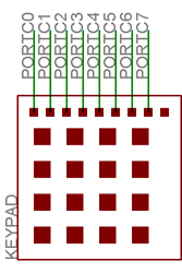
Figure 8: Keypad schematic
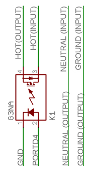
Figure 9: Relay box schematic
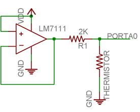
Figure 10: Thermistor schematic
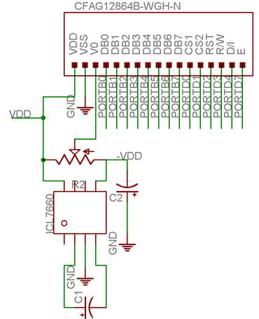
Figure 11: LCD schematic
Appendix C: Parts List
| Item | Cost |
| Omron solid state relay | Free sample |
| Maxim ICL7660CPA | Free sample |
| Used toaster oven | Free |
| LM7111 op-amp | In lab |
| Potentiometer | In lab |
| Crystal oscillators | In lab |
| Resistors and capacitors | In lab |
| Solder board | $2.50 |
| Power supply | $5.00 |
| Custom PC board | $5.00 |
| Keypad | $6.00 |
| Atmel Mega32 | $8.00 |
| Crystalfontz CFAG12864-WGH-N | $18.09 |
| AC receptacle connector | $0.64 |
| 3AG fuse holder | $0.75 |
| NTC thermistor x2 | $0.98 |
| Relay box hardware | $5.82 |
| TOTAL | $52.78 |
Table 5: Parts list
Appendix D: Tasks
Ko Ihara's tasks:
- Parts research, and sample requests
- Relay box construction
- Protoboard construction
- Various machining tasks
- Basic LCD pixel manipulation programming
- Control algorithm programming
Kashif Javed's tasks:
- Parts resarch
- Printed circuit board component population
- LCD graphical functions programming
- Line interpolation programming
- Control algorithm programming
Appendix E: References
Sample Sponsors:
Datasheets:
Vendor Sites:
Pictures
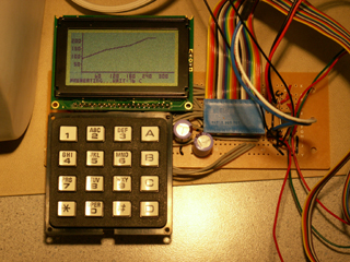
Figure 12: LCD board with target profile drawn
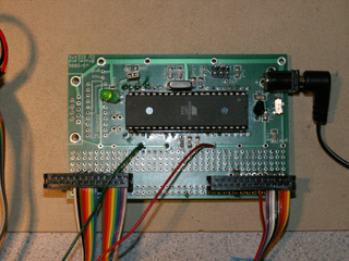
Figure 13: MEGA32 board
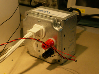
Figure 14: Relay box (front)
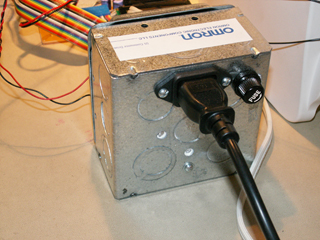
Figure 15: Relay box (back)
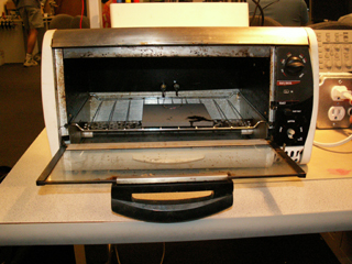
Figure 16: Hacked toaster oven with thermistor
Figure 17: Complete system picture
Acknowledgements
We would like to thank Omron Electronics and Maxim IC for their generous parts samples.
We would also like to acknowledge Professor Bruce Land for providing us with various
harnesses and connectors.