Guitar Demigod: Guitar Synthesizer and Game
By: Adam Hart, Morgan Jones, and Donna Wu
Introduction | High Level Design | Program/Hardware Design | Results | Conclusion | Appendices
Compose your own virtual guitar masterpiece or follow along with a preprogrammed classic. No experience needed!
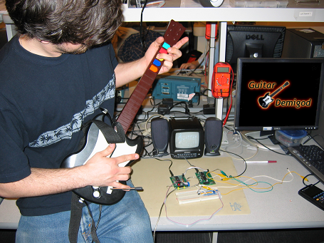
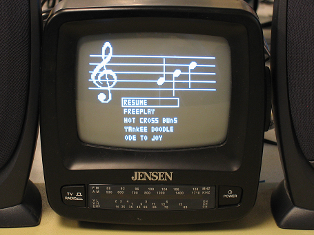
We developed a guitar synthesizer with video component inspired by the popular video game Guitar Hero. The original game consisted of only reproducing popular rock and roll songs but we wanted to allow players to be able to create their own music. The game uses direct digital synthesis to replicate guitar tones and outputs the sound to a set of computer speakers. A black and white television is used to view a video image which is produced using NTSC non-interlacing video code. The video shows the treble staff resembling actual sheet music as well the corresponding guitar tab. The user interacts using a guitar shaped PlayStation 2 controller to play notes and select from the menu. To imitate playing a guitar as realistically as possible, notes are played when the player "strums" the guitar controller and not when "fret" buttons on the neck are pressed. Another feature of our game that any musician will appreciate is that each note displayed on the staff corresponds to the correct pitch and frequency of the actual sound.
When we began looking at final projects, we wanted to do something fun. Other groups were planning clever and interesting projects, but only a few of them allowed for much user interaction. One of our group members owns the game Guitar Hero for the PlayStation 2 (PS2). The controller, shaped like a guitar, inspired us to make a game that utilized its unique look and button layout. After researching the PS2 communication protocol, we decided that we could use the Mega32 to talk to the controller, and the idea for our game began to take shape. At first, we just wanted to create a synthesizer that would produce realistic electric guitar sounds. Unfortunately, the input capabilities of the controller limited the number of actual chords or notes we could play and the size and power of the Mega32 limited sound generation to DDS, meaning that full guitar chords were out of the question. We also decided that we wanted a video component for the game so that the user could have visual feedback on the generated music, as well as follow along with preprogrammed songs for practice.
Our project's most complicated calculations are part of the sound generation unit. We perform two relatively complex calculations. First is the generation of a sine table to simulate the frequencies of musical notes. Through trial and error, as well as a bit of research, we decided that the first four harmonics of each fundamental musical note were needed to generate acceptable acoustic guitar sounds. During the initialization routine on the audio board, scaled versions of each of these harmonics are summed for every entry of the sine table. Since these calculations only take place during initialization, they do not have a significant effect on our timing or microprocessor load. The other set of significant calculations that we perform are for the envelope of the guitar output. In order to mimic the "pluck" sound and then resonate for a moment, we modulate the amplitude of the sine values to grow rapidly and then slowly die out. Ideally, the amplitude would decay exponentially, but we chose to keep it linear and are satisfied with the sound produced. In order to modulate, we modified Professor Land's optimized multiplication function to accept an integer and an 8-bit fixed point fraction. The result is an envelope that grows to 0.FF amplitude over two samples, and then dies out to nothing over 3/4 of a second.
The core of our project is communication. The game itself resides in the audio board, but it must collect data from the PS2 controller and transmit data to the video board in order to do anything meaningful. Both of these devices communicate with the master over a Serial Peripheral Interface (SPI) bus. For video communication, the audio board waits for the video board to request attention. In response, the audio board transmits a single byte of information with an opcode in the high nibble and data in the lower nibble. The opcodes cover all of the commands that the video board needs to accomplish, including shifting notes onto the staff, showing the menu, and selecting the menu options. This interaction occurs every two frames, when the video code reaches the user component and guarantees that the data is ready on the next frame.
To communicate with the PS2 controller, the audio board requests the attention of the controller's internal logic. Following the protocol of the PS2, the audio board commands the controller to send its button states, and the controller responds with 4 bytes of data that contain the status of the buttons, each stored as a bit. These bytes are stored for reference by the code that controls game play.
With this information, the audio board can update the state of the game. In freeplay or song mode, if the user is pressing a fret key and has just hit the strum bar, the DDS for the appropriate note is initialized. If the start button is pressed the menu appears regardless of the current point within a song. In menu mode, the strum bar toggles between the options, and the select button chooses one. Each of these state updates involves a corresponding video command which is transmitted during the next video attention request.
One of the places where we had to choose between hardware and software was our chip-to-chip and PS2 communication protocol. We could have written up our own bit-banged code to talk to our slave devices, but we chose to do it using the SPI hardware instead. For chip-to-chip communication, it was an obvious choice, as the hardware is built into the Mega32, and software transmission of data would add an unacceptable amount of overhead to our video code. Using the PS2 controller complicated things, because it meant that the bus would have to be shared. In addition, the PS2 protocol is much more complex than the single-byte opcode system that we developed for the video commands. In the end, we used the software to select between two formats of SPI communication, and were able to achieve concurrent communication on the bus.
Our code is split into two segments, one for the audio board that takes care of communication, sound generation and general game play, and one for the video board that takes care of the TV display.
The main board is responsible for generating the audio, communicating with the guitar controller, and running the actual game. Audio is generated using a simple DDS system based on Professor Land's examples. A lookup table contains 256 samples across one full period of the guitar waveform and is built by combining the first four harmonics. The first harmonic is weighted the most, and each successive harmonic is weighted less than the one before it. Values are extracted from the lookup table using a 32-bit accumulator, but only the most significant byte is used to reference the values in the table.
The DDS is controlled by timer 0, which is set to interrupt 62,500 times per second. Every time it interrupts, it outputs the current sample from the lookup table to the R/2R DAC. The accumulator is then incremented by a known amount determined by the frequency of the generated sound. Therefore, different notes can be produced simply by setting an appropriate increment. The increment is calculated using the following equation, with f being the desired frequency:
In order to make the produced tone sound more like a guitar pluck, the amplitude of the wave is modulated by an envelope. The envelope has three parts: attack, decay, and sustain. During the attack, the envelope increases very rapidly (from zero to maximum in only a few samples). The envelope then decreases rapidly during the decay portion until some critical value has been reached. Finally, in sustain the envelope decreases very slowly until it reaches zero.
The envelope is stored as a 16-bit unsigned integer representing a fraction. That is, the radix point is all the way on the left of the MSB. We wrote a specialized routine that multiplies a 16-bit signed integer by this fraction. Thus, a sample from the lookup table can be multiplied by a value from zero to (slightly less than) one in order to modulate the amplitude. Unfortunately, it turns out that we only ended up using an 8-bit signed char to hold a sample, therefore making our routine somewhat more complex than is strictly necessary. Regardless, our routine works exactly as desired.
The audio board is also responsible for communicating with the Guitar Hero PS2 controller, which uses a specialized digital protocol to communicate. The controller communicates over five lines: command (CMND), data (DATA), clock (CLK), attention (ATT), and acknowledge (ACK). It turns out, however, that the protocol used is similar enough to SPI that the controller can be directly connected to the Mega32's SPI pins. In our project, CMND goes to MOSI, DATA goes to MISO, CLK goes to SCK, and ATT goes to SS. Since SPI doesn't support acknowledge, we connected the ACK line to the INT0 pin on the Mega32, an external interrupt.
The microcontroller initiates communication with the guitar controller by pulling the ATT line low. Then, after a slight delay (experimentally determined to be about 7us), the start byte 0x01 is transmitted on CMND. The rest of the transmission is handled in the EXT_INT0 routine which is triggered by a rising edge of the ACK line (that is, when the guitar controller releases said line). The second byte transmitted is 0x42 which instructs the controller to send back button information. During the remaining three bytes of the packet, the microcontroller sends only 0x00 since it is only interested in receiving data.
While the second byte of the packet is being transmitted to the controller, the controller is sending back a mode identifier. In this case, the mode identifier is 0x41, indicating the controller is in "digital" mode (normal PS2 controllers also have an "analog" mode which allows for variable reading of the two joysticks). During the third byte, the controller sends back 0x5A which indicates that it is ready to transmit actual button data. Finally, during the last two bytes, the controller sends back the actual button presses. The whole communication packet is illustrated below:
| Byte # | CMND | DATA |
|---|---|---|
| 1 | 0x01 | idle |
| 2 | 0x42 | 0x41 |
| 3 | 0x00 | 0x5A |
| 4 | 0x00 | data |
| 5 | 0x00 | data |
Finally, the audio board is responsible for the actual game play. This is handled in a giant state machine in the main loop with the following states: Freeplay, Song, Menu, LoadSong, and Transition. In the Freeplay state, the user is in complete control of what notes are played. When the user strums, the microcontroller reads the fret buttons. If a valid combination was held down when the guitar was strummed, the accumulator increment is set accordingly and the audio microcontroller sends a SETSL command to the video board containing the note played. Between strums, the microcontroller is constantly sending the SET command with the current note being pressed, so that the user has real-time feedback before strumming.
In the Song state, the user can only play the next note in the selected song. When the correct note is strummed, the audio microcontroller sets the accumulator increment accordingly. It then loads the fifth note in the future from EEPROM and sends it to the video board with the SLSET command. In this manner, the current note and the next five are always displayed on the screen (until the end of the song). Entire songs are stored in the EEPROM as 0xFF-terminated strings of notes. The first song is stored starting at location 0 in EEPROM, the second song at location 64, and the third at location 128.
The Menu state is entered when the start button on the controller is pressed while in Freeplay or Song states. The audio microcontroller sends the MENU command with the appropriate menu ID (1, in this case). In the Menu state, the audio microcontroller keeps track of the current menu entry selected. When the strum bar is pushed up or down, the menu item selected is either decremented or incremented, respectively, and the new selection is sent to the video board in the MENUS command. If the start button on the guitar controller is pressed, the CLRM command is sent and the state machine returns to its previous state. If the select button is pressed, the current menu item is acted on. In all cases, the first command sent is CLRM. The next state is determined by the selected menu item. If it was "Resume," the state machine returns to its previous state. If it was "Freeplay" or any of the songs, the next state is the Transition state, with the following state specified.
Based on the specified next state, the Transition state sets the mode of video board. If the next state is Freeplay, the mode is set to freeplay. If the next state is LoadSong, the mode is set to song. The state is then updated according to the specified next state.
The LoadSong state is used to load the first six notes onto the screen. It iterates through those first six notes and sends them to the video microcontroller with the LOAD command, which loads the note buffer without updating the screen. When all six notes have been loaded, the audio microcontroller sends the video board the DISP command which forces it to display its buffer. The state machine then enters the Song state in the next cycle.
The commands are sent to the video board over SPI. The data request line (RQ) from the video microcontroller is connected to the INT1 pin on the audio microcontroller. The EXT_INT1 routine is set to run on the rising edge of that signal. Thus, the video board requests a new data packet by pulling the line high. When the interrupt is executed, the audio board transmits the one byte of video command over the SPI bus.
Because both the guitar controller and the video board communicate with the audio board over SPI, the audio board needs to keep track of which slave it is communicating with. It does this with a simple state machine with three states: Idle, PSX, and Video. In the PSX and Video states, it is communicating with the PS2 controller and the video board, respectively. In the Idle state, no communication is currently happening. Communication with either slave is initiated by setting a flag (PSX and Video have separate flags). Then, in the main loop, if a flag has been set and the SPI bus is currently in the Idle state, the appropriate transmission is initiated.
The video code is the more complicated of the two programs, but only due to the complexity of conforming to the NTSC format. Our display implementation was not interlaced, which is generally used when each frame is split into separate half-frames each consisting of all the odd or even lines. In our case, the even lines just duplicate the odd lines rather than contain unique information. Fortunately for us, the protocol is taken care of by Professor Land's sample code. The parts of the video code that we wrote deal with decoding transmissions from the audio board, and using those decoded transmissions to write to the screen.
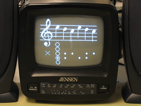
Our video display consists of a musical staff with a treble clef, 6 positions that can each take on one of 9 notes, 5 bubbles that indicate which fret buttons the user is or should be pressing, and dots that show the fret buttons that correspond to the displayed notes. The clef is very expensive to draw, time wise, so we only do it during initialization. The staff lines are drawn every frame, so that note erasure does not eat away at them, but they are drawn quickly by directly modifying the screen array.
The most important thing that the video code does is bring its SPI data request line (RQ) high at the end of every second frame. Until it does this it will not receive any data from the audio board. While a frame is being drawn to the screen, the video SPI buffer receives a 1 byte transmission from the audio board. The upper nibble consists of an opcode and the lower nibble consists of any data that the corresponding operation needs. The opcodes cover all of the various desired draw functions that the game requires. The most used of these is the NOP command. Usually, the audio board just wants the video board to keep a static display. Depending on user input, any one of the 10 other opcodes may be transmitted.
When MENU code is received, the video board pauses the display, clears the bottom of the screen in one frame and prints 5 menu options with a box around the top option in the next frame. When the MENUS code is received, the video board erases the old menu selection box and draws a new one around the option that the lower nibble indicates. When the CLRM code is received the video board removes the menu from the screen and redraws the bubbles and the dots. The bubble location is based on data transmitted in the most recent MODE code, which tells the video board whether the game is in Freeplay mode or in Song mode. MODE also clears the notes from the staff.
If Freeplay mode has been selected, the bubbles are drawn on the right hand of the screen. When the SET code is received, the video board erases any previous note over the bubbles and draws in the note that is indicated in the data sent along with SET. When the SETSL code is received, the note to the right of the bubbles is set to the value included with SETSL, and the rest of the notes are shifted one position to the left. This command takes two frames to complete because only 6 notes total can be drawn or erased per frame. To avoid flickering, the left three notes are handled in the first frame and the right three in the second.
If Song mode has been selected, the bubbles are drawn on the left hand side of the screen. When the LOAD code is received, the video board cycles a note from the audio board into the note buffer without displaying it. When it receives the DISP code, it writes the screen from the note buffer. That way, the user is not distracted by notes quickly flickering down the staff. This code only takes 1 frame to execute, because it only writes the notes to the screen. It does not erase any old notes. When the SLSET code is received, the notes are all shifted one position to the left, and then the right most note is given the value sent with SLSET. Finally, if the BAD command is received, the video board displays a small 'X' in the bottom left corner of the screen for a sixth of a second.
We defined a function in the video code that lets us draw and erase notes easily. We felt that the convenience outweighed the extra overhead of a function call. The function draws a series of vertical lines that form a note, as well as dots that correspond to the buttons presses for that note. The position of the note on the scale and dots are extracted from an array, indexed by the desired note. The function includes the option to erase a note, or to draw or erase only the dots. The latter capability is used to clear and redraw the bottom of the screen for the menu.
Since we only draw vertical and horizontal lines, we also wrote two functions (video_line_v and video_line_h) that plot points only in the y or x direction, respectively. They are not optimized, but are much better than the given video_line function, which accommodates lines of arbitrary slope.
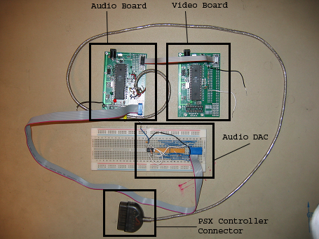
Hardware design for this project is not particularly complicated, but it consists of many subsections. The project centers around two Mega32 processors, each sitting on a PCB designed by Professor Land. The processor that controls video output uses the old revision 2 design, because its connections are relatively simple. The processor that handles the user input and sound generation uses the new revision 3 board to take advantage of the improved connectivity that it provides. Both boards' initial construction followed Professor Land's silkscreen indicators for component values and positions. We did not need RS232 capability, so we added neither MAX233 level shifters nor DB9 connectors.
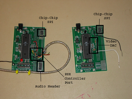
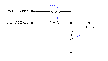
The video board needs to be able to output video signal to the TV and accept display data from the audio board. The video output consists of the three-resistor DAC that we used in Lab 4 shown in Figure 1. Since we chose SPI for our chip-to-chip communication protocol, our slave input comes through Port B into the SCK, MOSI, and MISO pins on the Mega32. We also defined a separate SS and RQ line for the video slave, also on Port B. These 5 communication lines go off-board via a 6-pin header. The 6th pin is used to give the boards a common ground.
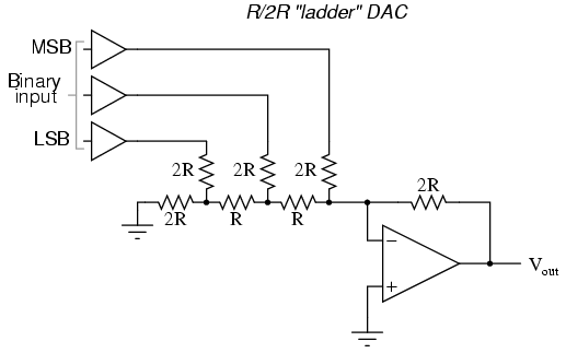
The audio and control board has three communication paths. The simplest is the audio output. We chose to use an R/2R DAC and simply brought the 8 pins from Port C to a clone of the STK500's 10-pin header. We included power and ground so that the DAC can filter the signal as well as run it through an op-amp. The output to the video board and input from the PS2 controller both use the Port B SPI pins for communication. They share the SCK, MISO and MOSI connections, but have separate attention and acknowledge lines. To command the attention of the PS2 controller, the audio board uses the actual SS pin on Port B. To get the attention of the video board, the audio board uses pin 3 on Port B. The acknowledge lines (RQ from the video board and ACK from the PS2 controller) come into the INT0 and INT1 pins on Port D so that they can be used for interrupt-based communication. The MISO and ACK lines required 1K pull-up resistors because the PS2 controller lacked internal pull-ups. The 5 video communication lines go off-board via a 6-pin header that is a clone of the header on the video board. The 5 PS2 controller communication lines are soldered on the board to a female controller plug so that the guitar controller is not permanently connected to the game.
The final hardware component is the R/2R ladder DAC. Through online research we found a simple 8-bit DAC similar to the one in Figure 2. We chose an R/2R ladder DAC because it is cheaper than an IC solution, is sufficient for our purposes, and could be acquired in a more timely manner. We used 10K and 20K resistor packs to ensure that the resistors were precisely matched, and built it on a breadboard. We originally planned to solder the elements to a solderboard, but due to time constraints and a budget surplus, we decided to leave it on the more expensive protoboard. After the resister chain, we added a unity-gain op-amp that improves the input and output impedances for the DAC and speaker, respectively, and a low-pass filter that removes the high frequency components from the input audio signal.
One of the limitations we ran into at the beginning of the project was the number of buttons on our PS2 controller. Originally, we wanted to be able to play at least two full octaves and possibly flats and sharps. Unfortunately, this would have required complicated and uncomfortable fret button combinations, and we decided to limit ourselves to nine notes. With only nine to worry about, traveling up and down the scale was relatively intuitive, but we had to sacrifice the range of playable songs. Fortunately, we still had enough notes to play simple, well known tunes.
Thanks to our use of two microcontrollers, we achieved great success in terms of execution speed. Implementing the video, audio, communication and game play calculations on the same microcontroller would likely have been unduly difficult or downright impossible. By splitting the tasks between separate hardware sets, we avoided significant slowdowns on both the audio and video ends. The result is a very smooth-playing, responsive game. Another contributing factor to our success was our ability to communicate with coexisting slave devices on the same SPI bus. The master indicates who it was talking to with separate attention lines for each device and prevents collisions in software.
Accuracy was important to our project in that we needed to create musical tones that resembled plucked strings closely enough to fool the human ear. Fortunately, the human ear is not a precision measurement device, so we were able to get away with a few simplifications in our design. Our DDS system uses a sine table of only 256 values for sound production. This resolution is sufficient to create a reasonable approximation of a sine wave up to a few kHz, so our 300Hz signals did not suffer much in that regard. We use 32-bit accumulators to step through our 256 values. This leads to some inaccuracy in the exact frequencies of our notes, but the discrepancies are inconsequential to the human ear. Below are the accuracies of our notes:
| Note | Correct Frequency |
Measured Frequency |
% Error |
|---|---|---|---|
| F3 | 174.6 | 174.7 | 0.06 |
| G3 | 196.0 | 195.7 | 0.15 |
| A3 | 220.0 | 220.3 | 0.14 |
| B3 | 246.9 | 247.7 | 0.32 |
| C4 | 261.6 | 260.9 | 0.24 |
| D4 | 293.6 | 295.4 | 0.61 |
| E4 | 329.6 | 330.2 | 0.18 |
| F4 | 349.2 | 349.3 | 0.03 |
| G4 | 392.0 | 391.3 | 0.18 |
Our project does not have much potential for human harm. It is possible that someone could turn up the speakers high enough to damage hearing, but that is an issue that faces nearly all speaker users, and is an effect of the speaker, rather than our project. Since we use an available consumer product for human interaction, most safety considerations are accounted for by the manufactures. We also do not transmit any information through the air at any frequency that could cause problems with RF sensors or other FCC regulated devices. In terms of interference, our project is less disruptive than a simple boom box or stereo.
We feel that our project is very easy to use. It offers 3 preprogrammed songs of varying difficulty, so that the user can understand how the notes are laid out and what sort of sounds to expect. Then, in freeplay mode, the user can experiment in any way he or she chooses. We selected our finger combinations such that they were simple to remember while still offering more than a full octave in which to play. Our video display either shows the user exactly which buttons to press (in freeplay mode) or a 5 note history (in song mode) so that they can see what they have already played.
Overall, our project was extremely successful in terms of what we had planned to do and what we were actually able to accomplish in the given time period. In our proposal, we had specified direct digital synthesis and a controller interface as the bare minimal requirement for our final project and considered additional functionalities such as video output and preprogrammed songs only if time would permit. However, we were able to include an in-depth video component as well as three preprogrammed songs in our final project. One shortcoming was our inability to mimic an electric guitar sound with direct digital synthesis, since we lack experience in generating the needed waveform. In the future, we could give a player the option of switching between the current acoustic guitar sound and a synthesized electric guitar sound. After careful examination, we decided that an acoustic guitar sound was more appropriate for the classic songs that we want to play in our game, such as London Bridge and Hot Cross Buns. Of course, there are plenty of additions that we could have made if more time was available such as more note variety and user-programmable songs. We feel that we adequately used our time and created a very polished final product.
During the course of the final project, we did not use any publicly available code except code written by Professor Land for the purposes of previous ECE 476 labs. He explicitly released this code to us in class. Any code that Professor Land provided was heavily modified and was only used as a backbone structure for our programs. For example, the video code used in Lab 4 served as the foundation for our video, and we utilized some of the smaller functions such as video_pt and video_putsmalls. However to increase the efficiency, we avoided using the video_line function and generated our own line functions that dealt only with vertical and horizontal lines. The direct digital synthesis code provided for Lab 2 was employed to generate the sound waveforms needed to produce the correct frequencies of each note. The major adjustments were including an additional three harmonics for a more accurate sound and modulating the amplitude of the waveform.
Our project relies on a number of communication standards. Most importantly, we used SPI to communicate between two Mega32s and between a PS2 controller and a Mega32. We made sure that data packets do not collide and that one pair did not monopolize the bus. Additionally, the PS2 uses a slightly nonstandard form of SPI, so our code changes how it communicates on the bus based on to whom it is talking. Another protocol that we used was NTSC. Conforming to the standard is largely taken care of in Professor Land's video code, but we did have to limit our instructions per frame so that we didn't delay the video signals. To accomplish this, we split the drawing-intensive commands into multiple frames, as well as optimized some of the video code for our specific needs.
1. to accept responsibility in making decisions consistent with the safety, health and welfare of the public, and to disclose promptly factors that might endanger the public or the environment;
2. to avoid real or perceived conflicts of interest whenever possible, and to disclose them to affected parties when they do exist;
3. to be honest and realistic in stating claims or estimates based on available data;
4. to reject bribery in all its forms;
5. to improve the understanding of technology, its appropriate application, and potential consequences;
Our project promotes understanding of the PS2 communication protocol. We have demonstrated that it is possible to talk to the PS2 controller over an SPI channel that is used by multiple slave devices. Many commercial products such as the PS2 are designed by engineers in a research and development site, completely separate from those who play the games or use the controllers. This project was our opportunity to become those engineers and modify a fabricated product to fit our specifications.
6. to maintain and improve our technical competence and to undertake technological tasks for others only if qualified by training or experience, or after full disclosure of pertinent limitations;
Often, the best way to learn is by actually doing and learning from mistakes. The concept of the project was very challenging since it called for the integration of many parallel components, such as a PS2 controller, a NTSC non-interlacing video display, a direct digital synthesis audio generator, and SPI communication. All of these parts had been reviewed at some point or another but never combined on such a large scale.
7. to seek, accept, and offer honest criticism of technical work, to acknowledge and correct errors, and to credit properly the contributions of others;
Throughout the weeks since beginning this project, we have responded to feedback from not only the professor but the teaching assistants as well. We fully acknowledge their contributions to the success of our project whether through the generous suggestions of ideas, countless attempts to help us debug, or gracious contribution of their own code.
8. to treat fairly all persons regardless of such factors as race, religion, gender, disability, age, or national origin;
9. to avoid injuring others, their property, reputation, or employment by false or malicious action;
At every point, we have strived for a safe environment for ourselves and others sharing our lab space. We paid extra attention to ensure that neither individuals nor properties were harmed during the course of our design project. Also since most of the equipment was shared among other students, everything was handled with extreme care and consideration in order to not damage public property.
10. to assist colleagues and co-workers in their professional development and to support them in following this code of ethics.
We believe that the most significant legal considerations we face deal with intellectual property laws. It is possible (although difficult to verify) that Sony has patented the communication protocol (which we have reverse engineered) that is used to communicate with the controller. However, our extensive research has indicated that the protocol is rather simple and doesn't seem innovative enough to be granted patent protection. Additionally, the protocol has been documented on numerous web pages and at least one magazine (Nuts & Volts) without explicit permission from Sony. By patent law, if the protocol was patented and Sony failed to protect their patent, they would lose protection anyway. Finally, since we are using this for a private educational purpose and have no intent to make a product, it is unlikely that we are in violation of patent law even if the patent exists and is actively being protected.
Another possible intellectual property concern we face relates to music currently under copyright protection. Since almost all modern music is still under active copyright, we knew that we would not be able to use pop songs as our preprogrammed demonstration music. Instead we chose to incorporate only songs known to be in the public domain. Hot Cross Buns, Yankee Doodle, and Ode to Joy all fit this criterion. In general, it is up to the user to know whether they can legally play a particular song.
| Part | Cost | Notes |
|---|---|---|
| ATmega32 x2 | $16.00 | |
| Custom PCB | $5.00 | |
| Custom PCB (old) | $2.00 | |
| Power supply x2 | $10.00 | |
| Protoboard | $0.00 | Donna's |
| Resistor-based DAC | $0.00 | Lab components |
| PlayStation controller extension cable | $5.00 | Bought at GameStop |
| B/W TV | $5.00 | "Rental" |
| Speakers | $5.00 | "Rental" |
| Guitar Controller | $0.00 | Adam's |
| Total | $48.00 |