Shashank Harshavat
sh272 Norbert
Huber nh48
476: Swing
A self-swinging, servo-based scale-model of a playground swing.
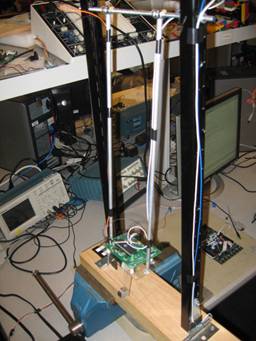
Figure 1: The swing.
Introduction | High Level Design
| Program/Hardware Design | Results | Conclusions
| Appendix
Introduction
One day Bruce had an idea. The idea was to build a
swing for the 476 Final Project. We took that idea, ran with it, and ended up
with this project. The project is based on an Atmel Mega32 MCU. The device
consists of a platform mounted in a swing-like fashion. The platform has an
attached servo motor that swings a heavy arm. The timing of the arm swing is
determined by an accelerometer configured as a tilt sensor. The operation is
autonomous. A picture is above in Figure 1. The rest is history.
Rationale
476
Projects are about building cool things that do stuff. Bruce’s idea of the
swing was perfect: a simple construction that does something impressive and
something that has not been done in lab before. The idea combines microcontroller
code with electrical and mechanical components so it is consistent with the
spirit of Cornell CDE courses.
Background Math/Physics
The
physics and math behind a playground swing are rather simple. We are all
familiar with the law of conservation of energy in equation below:
![]() constant
constant
Energy,
E, in a closed system is conserved. In an ideal swing, energy is simple
converted back and forth from purely potential energy, U, at the ends of the
swing, to purely kinetic energy, K, at the bottom of the swing. In our system,
we lose some energy to friction, but to make the swing go higher, we are simply
adding the potential energy, U, to the swing at appropriate times by raising
the center of mass, CM, of our swing. By adding potential energy we are
increasing the amount of energy in the swing and therefore make the swing go
higher. We can continue to add energy to the swing my lowering the center of
mass at the bottom of the swing, where there is no potential energy in the
swing to lose.
To
initiate the motion, we must force oscillations. The swing can be modeled as a
pendulum whose period is given by the equation below:
![]()
The
period of the swing (assuming small oscillations such as the ones immediately
after we initiate the swinging motion), T, is a function of gravity and the
length of the swing. We use this equation to force oscillations at the expected
frequency in order to get the swing moving.
Reference
(and pretty anime): http://www.bsharp.org/physics/stuff/swings.html
Logical structure
The main structure of our design is a feedback
control system, as shown in Figure 2:

Figure
2: Feedback Control System
Our
control algorithm is a simple proportional controller. We know when we want the
servo to move as a function of the position of the swing. When the swing
reaches the appropriate position, as senses by the accelerometer, our control
algorithm tells the servo to move, which influences the position of the swing,
and the feedback loop continues.
The
main structure of our electronics is shown below, in Figure 3:
Figure
3: Electronics Block Diagram
Hardware/Software Trade-offs
The
most obvious hardware tradeoffs are cost: our limited cost prevents us from
using high-quality, perhaps even custom hinges and other components, so there
is trade-off in overall performance and aesthetics in favor of staying within
the budget.
The
second trade-off is using a servo instead of a solenoid. It turns out that
affordable, off-the-shelf solenoids cannot generate enough force to
sufficiently alter the center of mass of the swing. As such, we decided to use
a servo instead.
The
third trade-off is using rigid rods instead of more authentic looking chains
for the rods that the electronics sit on. We sacrifice authenticity in favor of
a better functioning swing. Had we used chains, the lack of stiffness would
have introduced random motion to the swing that would have ultimately removed energy
from the swing and decreased our oscillations.
The
fourth trade-off is relying on software instead of hardware for much of the
control system. We elected to do all the programming and data reading in
software instead of relying on hardware amplifiers and comparators. This
decision reduced the amount of hardware that had to be built and enables us the
convenience of making rapid changes in software.
Relationship to Known Standards (IEEE, ISO, ANSI, DIN, et. al.)
We
did not encounter any situations where we needed conform to standards. The
nature of our design is independent of standards such as the IEEE standards
that govern RF (radio frequency) communication or ISO/ANSI standards that
govern video display conventions.
Relevant Patents, Copyrights, and Trademarks
The
simplicity of the project, that is, the goal to build something cool that does
stuff built from mostly scrap hardware isn’t exactly economically or
professionally viable. Our swing swings. That’s it. It is cool that we were
able to create an MCU-based swing for virtually no money, but our project
remains irrelevant in the world of patents, ™’s, and ©’s.
The 3
elements to the detailed design: mechanical design, electrical design, and software
design.
Mechanical Design
The swing is constructed using two metal beams mounted onto a large wooden
base. Across the beam is a metal rod which threads through eyehole screws hot
glued to two hollow aluminum rods hanging down in parallel. We chose hollow
aluminum rods to keep the swing as light as possible in comparison to the
oscillating weight. A five-inch by two and half inch Plexiglas plate is
attached to the end of the aluminum rods and the electronic hardware is mounted
onto it. The Plexiglas is chosen for its non-conductivity. For the weight that
is raised and lowered by the servomotor we attached a small cylindrical block
of tungsten to a Plexiglas arm, which is also attached to the rotating end of
the servomotor. Tungsten is very dense and provides a very compact weight,
while the arm is kept long relative to weight to increase the change in
potential energy during the operation of the swing. A picture is shown below in
Figure 4:
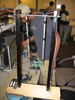
Figure 4: The mechanical design.
Electrical Design
The electronic hardware in the swing design consists
of three major components. First is the Mega32 microcontroller mounted onto the
custom PC board, which is responsible for control signals and proper timing.
Second is the FreeScale MMA1260 Z-axis,
1.5g Acceleration Sensor that acts as a tilt sensor to monitor the
position of the swing. The sensor provides around 4V when completely level to
the ground and then decreases its output as it is tilted. Finally there is the
S03N GWS servomotor, which lifts and lowers a weight up to 60 degrees in either
direction to provide energy to the swing. To control the direction of the
motor, the control line needs a 20ms period control signal with varying pulse
widths for each position of the motor. The servomotor is used due to its
adequate torque and its smooth transition. The acceleration sensor is attached
to the custom board and its output is connected to the A0 pin of the MCU so the onboard ADC on the Mega32 can
sample the sensor signal. The connecting wire is kept short to minimize
electrical noise that may corrupt the signal. The B0 pin of the microcontroller provides the control
signal for the servomotor but to ensure that sudden discharges from the servo
do not damage the Mega32, the pin is buffered from the servo control line with
a 4N35 optoisolator. Also, two DC supplies of 12V and 5V are used to power the
MCU and servo respectively to ensure isolation. The sensor is powered at 5V by
tapping the converted voltage off of the custom board’s power regulator. The wiring of the accelerometer is trivial.
The schematic of the optoisolator circuit is shown below in Figure 5. An image
of the PCB and accelerometer is shown in Figure 6.
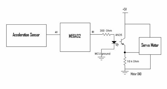
Figure 5: The optoisolator schematic.
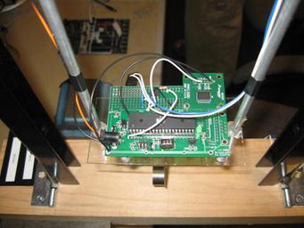
Figure 6: The PCB.
Software Design
The electronic hardware in the swing design consists
of three major components. First is the Mega32 microcontroller mounted onto the
custom PC board, which is responsible for control signals and proper timing.
Second is the FreeScale MMA1260 Z-axis,
1.5g Acceleration Sensor that acts as a tilt sensor to monitor the
position of the swing. The sensor provides around 4V when completely level to
the ground and then decreases its output as it is tilted. Finally there is the
S03N GWS servomotor, which lifts and lowers a weight up to 60 degrees in either
direction to provide energy to the swing. To control the direction of the
motor, the control line needs a 20ms period control signal with varying pulse
widths for each position of the motor. The servomotor is used due to its
adequate torque and its smooth transition. The acceleration sensor is attached
to the custom board and its output is connected to the A0 pin of the MCU so the onboard ADC on the Mega32 can
sample the sensor signal. The connecting wire is kept short to minimize
electrical noise that may corrupt the signal. The B0 pin of the microcontroller provides the control
signal for the servomotor but to ensure that sudden discharges from the servo
do not damage the Mega32, the pin is buffered from the servo control line with
a 4N35 optoisolator. Also, two DC supplies of 12V and 5V are used to power the
MCU and servo respectively to ensure isolation. The sensor is powered at 5V by
tapping the converted voltage off of the custom board’s power regulator.
All timing in the software is controlled by the timer0 compare interrupt. The clock is prescaled by 64 and
the OCR0 is set the to 67. The choice of OCR0 was the result of trial and error starting with 250,
then 125, and finally 67. The operation of the swing is divided into three
stages. Because the sensor is very inaccurate at low-level amplitudes, we
programmed two initial stages that can boost the swing up to amplitude more
appropriate for sensor operation. The initial stage is split into two 12-second
stages because the swing exhibits different fundamental resonance frequencies
at low and medium amplitudes. A long int called initcount is used to count out the 24-second cycle. The
interrupt updates initcount while still in the
first two stages of operation and uses if else branches to control desired
operation. In automatic mode the interrupt toggles a flag variable wait at half the resonance period. When wait is toggled back to zero, if else branches update the char variable width with one of two values. These values
correspond to the number of cycles needed to produce .85ms pulses and 2.1ms
pulses, which are the correct widths for the extreme positions of the motor.
The char variable flip is also toggled every time the
width is updated so the interrupt knows to alternate widths. Once the width is
set, the interrupt uses the pulsecount variable to time the appropriate sized pulse and output it to B0. The B0 pin is initially high, is set to zero when pulsecount equals the width, and resets to one once pulsecount has counted out 20ms. In the sensor mode the wait flag is set for a much
smaller period of time and is not set high again until the width variable is changed. This prevents noise from the
sensor readings causing the width to be updated sooner than desired and
prevents the motor from triggering rapidly in a small periods of time. Also in
sensor mode, the width is updated according to an algorithm rather than
automatically after a period of time. The read() function, which is timed by the interrupt and the variable time1 and is
called by the main function, reads the ADC samples every 100 cycles. It stores ADCH into Ain0 and then sets ADSCR.6 high to start another
conversion. The function also stores the previous 7 samples in Ain1-7. All these 8-bit samples are cast to int’s and summed together. Then the sum is right shifted
by three to divide by 8 and find the average of the samples to be stored as the
variable tilt. This process acts as
a moving average filter in an attempt to filter out random noise that can
corrupt the sensor signal. The read() function also stores the previous two tilt values for use in the triggering algorithm in the
interrupt. While in sensor mode the interrupt checks to see if tilt is below a certain threshold which indicates swing is
in the center position of its range. If
this is true and if tilt has either stayed the
same for the previous two cycles or has increased over time, we know that the
swing is in one of the extreme positions of its range or is falling. Then width is updated to the opposite value and the motor swings
the weight 120 degrees to the opposite extreme.
Problematic Design Elements
The solenoid approach did not generate enough change
in the center of mass to generate the swinging motion.
The accelerometer does not have enough resolution to
work at low amplitudes.
Speed of Execution
In the end the swing worked better than we had hoped.
The autopilot stages worked extremely well in getting the swing to moderate
amplitudes and once the sensor mode kicked in the swing really started to fly.
We had to turn off the swing just for fear that the swing might swing
completely around and break some wiring.
Accuracy
The sensor works well at larger amplitudes but is
completely unreliable at lower amplitudes. If a more sensitive sensor was
utilized we could imagine not having to use the autopilot stages at all. The
simple moving average filter we utilized to de-noise the sensor signals turned
out to work pretty well. We found no need to incorporate a more sophisticated
filter, as this would have just eat up computation time.
Our initial approach for the swing utilized a
solenoid to raise and lower the entire circuit. The problem with this approach
was the solenoids were very weak and didn’t move the weight very far so our
change in potential energy was very small. Also the solenoids motion was very
jerky and this caused sudden vibration on the swing that both disrupted the
sensor and also disrupted the swinging motion. Bruce and another one of the
swing groups suggested we switch to a servo. By changing to the servo, we were
able to lift much more weight for larger range of motion with very smooth
transition. Regretfully we did burn out one servo due to overloading. Other
than that the servo turned out ideal.
Design Safety
As far as safety, we always made sure for high
amplitudes to never stand in the path of the swing or point the swing at any
other groups. We made sure everything that could potentially fly off was firmly
attached to the swing. Repetitive noise from the servo may have annoyed some of
the groups working next to us so we apologize. Still in the end, I think the
fully functional swing gave the other groups something interesting to look at
while they were taking a break from their own work. No one was hurt in the
process of making this swing.
Interference (e.g. CPU noise, RF noise)
We
had no relevant interference issues with other groups.
Usability
The simplicity of our design allows anybody to simply
walk up to the swing, flip the switches, and stand back to watch it go.
Although the design required the information obtained throughout educational
experience, the final product is as simple as a child’s toy.
Result Analysis
Our
swing works a lot better than expected. Our initial use of a solenoid was
disappointing at best, but the consequences of the consequent use of a servo
were surprising. We are happy that we did not need to implement a more
elaborate control system. It is nice to know that the swing generally worked
more or less as we originally intended it to.
Our
results exceeded our expectations: we were able to get excellent performance
without any additional elaborate software or hardware. We even have an icing on
the cake since we will attempt to swing in a full circle during the demo.
For
next time, replaced the rigid rods with chains would make the swing more
authentic. We could also make the swing prettier and add flare by including
buttons to control the maximum amplitude, for example. To make things
interesting, we could turn this into a dynamics and feedback problem by
creating a swing that starts from a standstill and ends balancing itself
upside-down at the top of the swing. Unfortunately, I believe that this
interesting project would be outside of the budgetary constraints of the
project.
Intellectual Property Considerations
Intellectual
property is effectively nonexistent in the design of our project. In terms of
mechanical design, we built a scale model of a common playground swing, which
lacks significant science behind such construction. In terms of electrical and
software design, the circuits and code use elementary principles that can be
found in any physics textbooks. There are even two other groups this year
constructing very similar swings. Therefore, there are no patent opportunities.
We did not reuse code, use an existing design, or signed any NDAs.
Ethical Considerations
In
the context of the IEEE
Code of Ethics, all the claims made in this report are supported by the
operational swing (Rule 3); we elected not to sell our project to one of the
other swing groups (Rule 4); we were qualified to use all tools and components
involved in the project (Rule 5); we incited constructive criticism from Bruce,
his team of TAs, and fellow students and noted all external contributions (Rule
7); and we encouraged the open use of our power-tools by other groups (Rule
10).
Special Thank You
We’d
like to thank Bruce for the idea itself and his general ability to kick ass and
fix all of our problems. We’d like to thank the TA’s, especially Gus wasting
multiple hours diagnosing our ignorant problems. Most of all, we’d like to
thank Konstantin Klitenik for providing back up servos and for being our
personal project consultant in the late stages of the project. Without these
people, our swing just would not swing.
Appendix A: Code
#include
<Mega32.h>
#define
begin {
#define
end }
#define
t1 100
//12
seconds
#define
init 44776
//24
seconds
#define
init2 89552
void
initialize(void);//initialization stage
void
read(void);//reads ADC and filters input
//variable
declarations
unsigned
char time1,Ain0,Ain1,Ain2,Ain3,Ain4,Ain5,Ain6,Ain7;
unsigned
int temp,count;
unsigned
char tilt,oldtilt1,oldtilt2,wait,flip,pulsecount,width;
long
int initcount;
//interrupt
drives timing for read() function and times out different
//stages
of swing operation
//first
stage swings automatically at low amplitude period for 12 seconds
//secod
stage swings automatically at medium amplitude period for 12 seconds
//third
stage uses sensor to trigger the motor at ideal time
interrupt
[TIM0_COMP] void timer0_compare(void)
begin
//iterate timer variable for read()
function
time1--;
//iterate init counter while still in auto
mode
if(initcount <= init2) initcount++;
//time wait flag to halt operation for number
of cycles
if(wait == 1) count++;
if(initcount >= init2)//sensor mode
begin
if(tilt < 195 && tilt <=
oldtilt1 && oldtilt1 <= oldtilt2 && wait == 0)//detect
extreme postion if not halted by wait flag
begin
if(flip == 0)
begin
width = 8;
PORTD.7 = 0;
flip = 1;
end
else
begin
width = 3;
PORTD.7 = 1;
flip = 0;
end
wait = 1;//set wait to halt further
action
end
end
else//if not in sensor mode dont detect
extreme position, just trigger motor when not halted by wait
begin
if(wait == 0)
begin
//use flip variable to alternate
direction of servo movement
if(flip == 0)
begin
//update pulse width for control line
and light LED for debugging
width = 3;
PORTD.7 = 0;
flip = 1;
end
else
begin
width = 8;
PORTD.7 = 1;
flip = 0;
end
wait = 1;//set wait to halt further
action
end
end
//create pulse for servo motor conrol with
appropriate width
if(pulsecount == 74)//74cycles counts up 20ms
periods
begin
PORTB.0 = 1;
pulsecount = 0;
end
else if (pulsecount == width)
begin
PORTB.0 = 0;
end
pulsecount++;
if(initcount <= init2)
begin
//first stage trigger servo every half low
amplitude period
if(initcount <= init)
begin
if(count >= 2487)
begin
wait = 0;//resume
count = 0;
end
end
else//second stage trigger servo every half
med amplitude period
begin
if(count >= 2568)
begin
wait = 0;//resume
count = 0;
end
end
end
else//sensor stage, just prevent rapid
triggerings of motor
begin
if(count >= 1200)
begin
wait = 0;//resume
count = 0;
end
end
end
void
main(void)
begin
initialize();
while(1)
begin
if(time1 <= 0) read();//read adc every
100 cycles
end
end
//reads
ADC ad filters output
void
read(void)
begin
time1 = t1;
//store previous 7 values
Ain7 = Ain6;
Ain6 = Ain5;
Ain5 = Ain4;
Ain4 = Ain3;
Ain3 = Ain2;
Ain2 = Ain1;
Ain1 = Ain0;
//get new sample
Ain0 = ADCH;
//add all samples and divide by 8 to average
temp = ((unsigned int)Ain7 + (unsigned
int)Ain6 + (unsigned int)Ain5 + (unsigned int)Ain4 + (unsigned int)Ain3 +
(unsigned int)Ain2 + (unsigned int)Ain1 + (unsigned int)Ain0);
temp = (temp>>3);
//store previous two averages for interrupt
algorithm
oldtilt2 = oldtilt1;
oldtilt1 = tilt;
tilt = temp;
//start another conversion
ADCSR.6 = 1;
end
void
initialize(void)
begin
DDRB=0xff;
DDRD= 0xff;
TIMSK=2; //turn
on timer 0 cmp match ISR
OCR0 = 67;
//set the compare re to 67 time
ticks
TCCR0=0b00001011; // clock/64 and enable interrupt
//init count variables
pulsecount = 0;
time1 = t1;
temp = 0;
flip = 0;
initcount = 0;
//init the A to D converter
//channel zero/ left adj /int Aref
ADMUX = 0b01100000;//using Avcc
//enable ADC
ADCSR = 0b11000111;
//enable interrupts
#asm
sei
#endasm
end
Appendix B: Schematics
Appendix C: Parts List
|
Parts |
Quantity |
Cost |
|
Atmel Mega32 Microcontroller |
1 |
8.00 |
|
Custom PCB |
1 |
5.00 |
|
MMA1260D Accelerometer |
1 |
Sampled |
|
4N35 Optoisolator |
1 |
Free (lab) |
|
Power Supply |
2 |
10.00 |
|
Solder Board |
1 |
2.50 |
|
Servo Motor |
1 |
10.00 |
|
Swing Frame |
1 |
Free (scrap) |
|
Swing Aluminum rods |
2 |
4.00 |
|
Swing Hooks |
2 |
1.00 |
|
Tungsten Ball |
1 |
Free (lab) |
|
Plexiglas |
1 |
Free (scrap) |
|
Various resistors and capacitors |
|
Free (lab) |
|
Various plastic parts and stuff |
|
Free (scrap) |
|
TOTAL COST |
|
40.50 |
Appendix D: Task Breakdown
Shashank: software design, control algorithm.
Norbert: mechanical design, hardware design.
Appendix E: References
FreeScale
MMA1260D Accelerometer