The essential components of the hardware system are
- Protoboard and MCU
- Gyroscope
- XY-Accelerometer
- Z-Accelerometer
- Helicopter
- Motors
- “Launch Pad” and IO Tether
- Power Supply
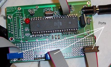
Protoboard
The Atmel Mega32 microcontroller is mounted on the provided custom made protoboard. We added three ports, for interfacing with the motors and sensors. Port A is used for receiving the outputs from the sensors, Port C is used for the PWM outputs to the motors, and Port D is to interface with buttons that are used to turn on the helicopter as well as the debug LED which proved invaluable for the development of our project. Due to the current that is required by the whole system, we replaced the voltage regulator with a LM340 5V regulator that can support our design's current needs better.
The Push buttons were used for some basic debugging and testing purposes, however, they were mainly implemented for the purpose of starting up the helicopter flight routine without introducing any sort of vibration/electronic noise into the system. This allowed us to turn on the helicopter without touching anything sensitive and allowed us to better balance the craft once we got down to the nitty gritty aspects of making the stability system tight enough to work within the length of our IO tether.
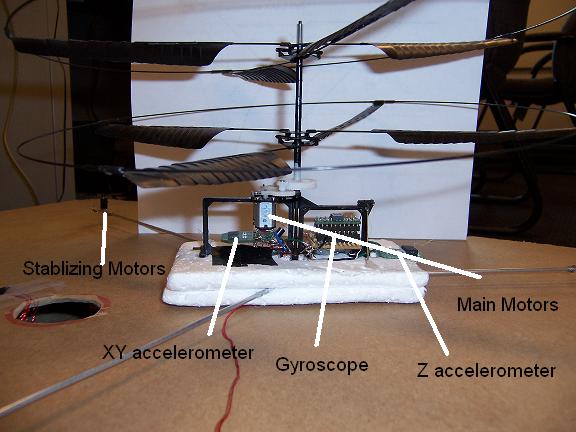
Helicopter
We bought a Blade Runner RC helicopter from Ebay for $10. We tore this apart, removing the chassis, RF receiver, and lithium ion battery. We used the rest of the parts, namely the gears and rotors for our design. This was done since we did not have the facilities, budget or time to design and build these ourselves. The structure of the helicopter is such that there are two main rotors to provide lift that are individually controlled through their own motors and gear systems. For the body of the helicopter, we glued the whole gear system on to a slab of Styrofoam. Since weight is especially a key issue, we decided to wire everything with 36 gauge wire, which reduces its impact on weight. Due to the number of wires that are to and from the helicopter, we decided to connect them to jumpers for easy interfacing. Below is an early conceptual model that demonstrates the design of the Helicopter's geometry.
Motors
To interface with the total of five motors (2 main, and three for stabilizing), we designed a 5 channel optoisolator circuit that was based off the one used in Lab 5. The diagram for a one channel optoisolator is shown below. Essentially, this circuit is duplicated five times on a solder board.
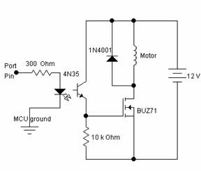
The main motors came with the helicopter are Mabuchi motors (part # FF-N20PN), which are rated at 1.5 -6 V, and 14600 r/min with no load. We believe that these motors are sufficient to meet our goals of the project. From the optoisolator circuit, Vcc is common to all of the motors and the grounds are independent. Hence, we connect the positive leads together while we use the ground wire to individually control the motor speeds.
We plan on using smaller motors ( 0.20" diameter x 0.4" long), which operate at 1.5-3Vdc at 110 mA, as the stabilization system. We bought these from AllElectronics.com (CAT# DCM-255). Essentially, these motors come out from the body of the helicopter, and provide tilt about the x and y axes. To do this, we experimented with different types of rod material that would be light, yet rigid enough to support the motors. We finally set on using 1/16” diameter hollow aluminum rods, so we can run the power cables through them. To mount the motors onto the rods, we used the glue gun to create a mat of insulation between the motors and the rods, which also acted as the adhesion layer. Finally, we also glued the rods to the new Styrofoam chassis with the proper geometric spacing of 120 degrees between each rod maintaining that the distance from the main rotor shaft to the stabilization motor on that rod was equal among all of the rods. Similar to the main motors, the power for these motors was all common, thus we can control them just by having their ground wire interfaced through. Thus only six IO wires are required for all of the five motors.
"Launch Pad"
For practical reasons, it made sense to use a base where the helicopter can take off and land, while all the wires are out of its way. Hence we chose to elevate the base where the helicopter launches off. We managed to build this off scrap found around campus, namely a particle board with wood pieces stuck to it. The IO tether ended up being a large part of the design process since we had to make sure that the helicopter would gain enough altitude to have the ability to stabilize but still not too much so that it could have some slack on the line even if it moves laterally to stabilize.
Gyroscope
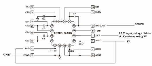
We were able to sample a single chip rate gyro from analog devices (ADXRS150EB) . As this comes packaged already as an evaluation board, no soldering had to be done. To mount this onto the helicopter, we used a DIP socket, which was mounted on a small piece of solder board. The way we interfaced to gyroscope is shown blow. We built a voltage divider to provide the reference voltage needed using 2 1K ohm resistors, since the input voltage is 5V. We finally placed this onto the chassis of the helicopter.
XY Accelerometer
Freescale provided our lab with samples of ± 1.5g Dual Axis Micro-machined Accelerometers (MMA6261Q), which were sufficient for our needs. As these come in rather bulky evaluation boards, we dremmeled off most of the board to loose as much weight as possible. Since this accelerometer requires a 3.3V input, we use a 2490 power regulator provided by Freescale as well to provide the necessary voltage. The way we interfaced to this chip is shown below. This chip was also placed in the helicopter chassis but not coupled to the chassis as can be seen. This was a crude version of a motion isolator we used to try and absorb vibration noise from the propeller motion. In experimentation we noticed that this lowered the peak-to-peak level of the noise due to the main motors on at 50% power from 1 Volt to .5 Volts simply on the oscilloscope. This combined with our real-time averager provided us with a very robust system for determining the tilt of the craft as explained in the software section.
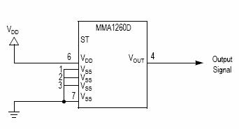
Z accelerometer
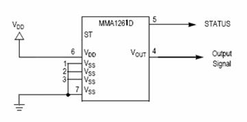
Freescale also provided low g micromachined accelerometers (MMA1260D), with specifications sufficient to meet our needs. Again, we dremmeled the boards down to cut down weight. As the only required voltage is a 5V DC input, no voltage regulator or divider was required. The evaluation board was finally placed on the Styrofoam base, towards the front of the helicopter, which also provided a better balance.
Power Supply
We were able to get a 250W ATX power supply from the ECE department, which is able to power our whole system. Initially using the power supplies in class, we noticed that there were voltage dips whenever the system is on (between 2 and 3V drop), and hence not very reliable. Now using this power supply, these voltage dips are reduce to maximum of .5V.
The stability system consisted of 4 different control feedback systems. We experimented with various different methods of producing reliable results and below are our conclusions. In the end our software was capable of having the helicopter demonstrate autonomous stabilization in all X, Y, and Z axes as well as stabilization in it’s rotation about its Z axis. We will describe how each of these control feedback systems was implemented.
Gyroscope
This was the first of the control feedback systems to be designed. We had a very good amount of success with this one which we later found out was due to the gyroscope’s immunity to vibration noise that was very common in our mechanical system. Our first pass in designing this system was considerable successful:
First the gyro’s level at no motion was calibrated at the start of the program. This was done by waiting a while and then assuming that this was the point where the helicopter was stable and to save this value as the gyro’s calibration point. Then the system was rather simple. The code would wait for an analog conversion to complete and then check the value coming out of the gyro. If this value was different than the gyro’s calibration point we knew that the helicopter was rotating in a known direction and we would adjust the PWM signal to each motor accordingly. This was a linear adjustment and no PID was necessary in this system. This was our trim adjustment.
At first this was very effective so we did not venture to incorporate a PID into this design. The helicopter would self compensate and very quickly reach an equilibrium. This worked very well on the ground where friction was present. However in the air we started to notice some strange effects. At this point we had implemented some basic run-time averages for some of the other sensors so we decided to apply this method to the gyro scope and this worked very well. This was where we tried to implement a PID and the helicopter would oscillate wildly. To quell the oscillation would have required too much processing power and not enough benefit since the simple 32 run-time average was much more effective and dampened quite quickly even when the adjustment levels were very low.
The Run Time Averages
Later in the design process while implementing and integrating the Z-Accelerometer we noticed that no matter what we did, we could not get a reliable result when the propellers were on and incorporating an immense amount of noise into the system. These were due to vibrations in the mechanical system and were impossible to fix using many methods that we tried such as analog low pass filters of very low cut-offs as well as mechanical motion isolators. What we ended up doing was to implement a run time average. This way the noise would be averaged out and we would get the average value out of the sensor. This method ended up being used for all of the sensors on board. Also a basic motion isolator was used for the X,Y accelerometer: the accelerometer was decoupled from the chassis and the only thing holding it up were the wires that provided its connections to power and its output. This allowed some of the vibrations to be absorbed by these "springs."
This method was rather simple. First we would calibrate the sensor. This was done in a similar manner to the first method we used with the gyroscope but more sophisticated. We would set up an array of the length of our filter. This length had to be of size 2 n (where n = 1, 2, 3 …) so that we could use shift operations for quicker computation. For our purposes these sizes were satisfactory. Using a loop an analog conversion would be run for every array element. This would fill up the array which was used as a buffer. The calibration variable was then set to the first average of this buffer which was assumed to be the most accurate representation of the calibration point of the craft when it’s not moving.
To use this buffer during the actual program we could run the analog conversion of the specific sensor and take its value and put it and the end of the array and then move the rest of the array down by one bumping off the last array element. Then we would take the average of the buffer and use this as the value of the sensor and compare it against the calibration point. This method proved very effective and was simple to use since if we wanted less noise we would simply increase the size of the buffer. However, we had to be careful in doing this since if we had too many of these averages running and they were too long then the system would become slow and inaccurate and also potentially oscillate.
The X and Y Accelerometers
For these stability systems we simply had to control the PWM signal sent to the three stability motors. Using the run time average system described above we would discern when the helicopter was tilted in a specific angle. Then using some basic trigonometry we could see the relative weights that we had to add to the signals or subtract from them. These are shown in the diagram below,
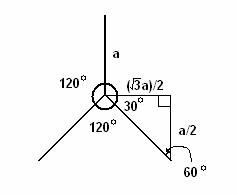
This means that to rotate the craft about the x-axis we could apply one unit of force to the front motor to tilt it one way or apply one unit to each of the other two motors each to tilt the craft the other way. This is because that the lever arm of the other two motors is half as effective as the lever arm of the front motor. This was rather convenient for us.
The other axis was a little more complex. We decided that we would simply use the two motors capable of providing tilt about the y axis rather than trying to compensate for the resulting x axis tilt with the front motor since this could potentially defeat the x-axis accelerometer algorithm. Instead we just used the two of them with equal powers to adjust for y-tilt and let the x-accelerometer system take care of the resultant x axis tilt.
Also, we implemented a variable for each axis which represented how flat the craft was. This was later used in the Z accelerometer for a short while to gauge whether the Z accelerometer was getting a bad sensor reading due to the fact that its orientation was tilter and its acceleration of gravity different. This was something we wanted to avoid since we only wanted the Z accelerometer to gauge up and down motion and not tilt.
The stability system was generally turned on after the helicopter had reached a certain upward momentum. This was to ensure that the stability motors would not be affected by take off which needed to be a smooth and quick upward motion which could potentially introduce shock into the system and send the sensors to ill-readings. Also, since power management was a problem in our initial design we implemented some limiting speeds to the stability motors. Although these did not matter too much when we fixed our power supply to something more reliable, it was very useful since we could adjust how fast the helicopter reacted as well as smooth out the stability system and not give it too much power. This allowed for a much more gradual and sustainable stability.
The Z Accelerometer
This was the hardest of the systems to implement. We basically spent a good amount of time playing with the thresholds until we found a good stability point. The same method was used as for the rest of the systems. However, this one was a good deal touchier. In the end we had to cater our helicopter takeoff routine around this sensor and basically only let it turn on when we were generally sure that the helicopter had gained enough altitude so that maintaining an altitude was not too close to the ground where all of the mechanical lift systems would simply fail. This was one of the few sensors in which we had to hand find the threshold for which the system behaved correctly. This was found to be minimal and was just some basic noise rejection methods.
The Helicopter Stability Routine
We defined more helicopter states than we implemented although the states defining lateral movement would have been easy to implement but we did not have enough time to fully test them as well as the fact that our cables were not long enough to truly demonstrate this functionality. The routine the helicopter takes to demonstrate stability is a rather straight forward one and toggles between the different stability systems as to give it true autonomous behavior. These states are toggled through by a very basic timing system that does not really use seconds or milliseconds but time increments that we catered to our needs (although they are labeled as otherwise).
GROUND – This state was used before TAKEOFF. No stability systems were turned on other than the gyroscope and usually the speeds of the rotors was zero or around 30%. This allowed for some trim calculations to be done before the helicopter took off but these did not prove too effective and were cut out in later versions.
TAKEOFF – This was the most sensitive part of the flight process. If the helicopter took off in a strange way then this behavior would take a while to smooth out over the expanse of the flight and often times was beyond the reach of our cables so we focused on this phase more than the others. Basically the helicopter required a quick increase in rotor speed to give it the initial upward motion to get up in the air. This made us push the rotors to 95% (to give some space for gyroscopic adjustments to take place). It took some trial and error but we finally calibrated the take off routine to work well with the gyro and then we were able to gyroscopically stabilize take off. This proved very effective in later tests. All other stability systems were turned off to make sure that the takeoff motion was done in as close to a vertical manner and that no shock signaling would alter this upward trajectory and send the helicopter in an unpredictable lateral motion.
HOVER – Although an intermediate state was implemented named STABLE which was when the stability system was turned on and the altitude compensation system was not this was the extent of the state and needs no further explanation. The HOVER state is the state which the helicopter reaches when it is ideally meant to hover. At this point all of the stabilization systems are working and generally the helicopter will experience fluctuations based on the ambient air currents but will compensate for them rather quickly. This state was quickly switched on after the TAKEOFF when we assumed the helicopter reached a high enough altitude for the stability systems to be effective.
LANDING – In this state all systems are turned off other than the gyroscope. This state simply lowers the speed of the main motors until they reach a certain threshold where the helicopter is sinking downwards. This is meant to cause a gradual decrease in altitude and in turn land the craft gracefully. This is the simpler of the states since we assume that the craft has reached stability by the time it reaches this state and the altitude was minimal so it would land quickly and with no problems. This state is turned on after our hovering grace period is over.
For a good portion of the program we used Bruce Land’s fixed point code that we had used before in lab#4. This allowed us to have a greater control and resolution in incrementing and decrementing the PWM signals. Other than this all code was originally written and any code used other than this was used for reference only.
Results of the design
Mpeg Video
Our design performed to our specification and demonstrated the ability to autonomously take off, stabilize and land. Although the design could have used some polishing and streamlining, our system demonstrated all of the capabilities that we set out to accomplish. The helicopter could stabilize itself in it's rotation about the z axis where it was obviously maintaining it's orientation. This was seen to be done to quite a good accuracy where it would stay within one rotation of it's original take off position. Also this did take a second or two to occur and some basic oscillation was noticed, but this oscillation was very obviously damped and for a frictionless system was very impressive.
The helicopter could stabilize about its x and y axes. This was slightly laggy due to the fact that the processor was running so many different averages and analog to digital conversions. This also exhibited some basic oscillations but these oscillations were also noticed to be dampening although our tether restrictions never let us test this out all the way. However, this behavior was seen over and over in tests and assumed correct. The tether really limited our testing of the system since stabilization could not occur at too low of an altitude otherwise strange pressure differentials would be created and the helicopter would randomly sink. This limited the lateral range of the helicopter's sterilizations before the tether picked up too much slack and began to exert forces which the helicopter was not powerful enough to compensate for (although it was observed that it tried and maintained its altitude for a more extended period of time than it would have otherwise).
The helicopter demonstrated capability to perform basic altitude control using the Z-accelerometer and maintain an altitude. This was noticed in multiple tests and was slightly laggy since we decided to make this specific system very smooth to eliminate any chance of oscillation since this would be disastrous to the helicopter's ability to maintain an altitude. Instead a very gradual increase and decrease of motor speed is used but was quick enough to compensate for altitude changes once a high enough altitude was reached.
A function of the helicopter that was no demonstrated and implemented but that our design is definitely capable of is non-vertical motion. This was demonstrated in the stability system and demonstrated to us in experiments that if we had implemented this portion in the code it would definitely have worked. The main reason we did not implement it, however, was due to the shortness of the IO tether which would not allow us to see any real demonstration of lateral movement. In fact the lateral movement due to the stability was already too much for it in many cases (this was usually a 10-20 cm movement, or about one craft diameter which is rather good and sustainable).
The usability was rather simple as it required the push of a button and the helicopter did the rest. It was hard to predict whether or not it would work since it depended on the orientation of the takeoff, balance of the craft, and the IO tether. We had to calibrate all of these external variables to such a threshold where their effects would be negligible enough during take off that the stability system, once it kicked in, would be able to stabilize the craft without leaving the area in which the IO tether applied negligible force.
This design was very safe and robust as well as did not produce any interference with any one else's projects. The safety rings around the helicopter rotors allowed for safe collision of the helicopter with objects and people and the stabilization arms extended a little bit beyond the motor so that the rotor would not immediately hit anything. Also the speeds of the stabilization motors, which were the only motors with rotors that could potentially hurt anything, were not run at a speed sufficient to harm anything. Also to enforce safety in the design we made sure that there were at least two people present when operating the helicopter and that people were backed away enough so that in case something went wrong the chances of hurting anyone was minimal. In all reality, however, the helicopter was so small and the motors so weak that it couldn't have broken the most sensitive of skin or rubber insulation.
Overall the results of our project were a great success. The ambitious nature of this project really pushed us to our limits and we are very happy to say that we succeeded in producing a successful autonomous stabilization system for a co-axial helicopter using our proposed stabilization system. No real changes were made to the original design and we managed to apply the theory and have it work in application. This system can now be used and integrated into a more complex system which could potentially be an intelligent indoor autonomous navigating helicopter.
Conclusion
We aimed to have a fully stabilizing and laterally moving helicopter but our results just fell short of that. However, we are very happy with our results especially since we accomplished so much in such a short time. Obviously, given more time and resources, this project can be taken further to a fully autonomous helicopter.
Things we would change next time around would be to use even lighter materials for the stabilizing rods, as well as figure out better cable management on the helicopter. Since many power cables were common, we soldered a lot of leads together with excessive solder. A more robust adhesion system would be thought of to limit excessive glue, as well as reduce noise. One possible solution to this might be the integration of springs to decouple the system from the chassis. Finally, again since size and weight is always an issue, we would use a 5 channel optoisolater circuit rather than 5 one channel optoisolator circuits.
Our project did not have any standards to adhere too. Since the design we used is custom designed, we also did not have to worry about infringing on any patents. The algorithms implemented are all designed by us. Thus, we believe the stabilization system we designed for such a helicopter may actually have patent opportunities.
Ethical Considerations
We chose a project which we feel we were competent enough to finish, as well as improve our technical ability. Our project does have several safety concerns that need to be considered. The helicopter will be using several propellers for lift and stability reasons, which have the potential to cause harm. However, the rotors are all made of plastic to limit any damage in the event of accident. We also inherently minimize the risk of accident due to the wires connected to the helicopter, which acts limits the distance it can fly and possibility of accident.
We are well aware of what this system is capable of, as well as our technical abilities, and never lied about what it, or we, can or can not do. We always asked for help from the TAs when we didn't understand why something happened when we didn’t understand. We always welcomed criticism and feedback on our designs. We made sure that our project at any cost caused harms to other individuals or their projects by setting up far away and limiting cable length. Finally, we rejected bribery in all forms, including food.
Legal Considerations
Since all the design and code will be ours, we will not be interfering with intellectual property rights besides the knowledge provided on how to interface with the components that we use (e.g. datasheets). Also, since no RF is being used in this project, no FCC regulations need to be taken into account. We assume that the amount of electromagnetic interference created by the MCU will be minimal due to its relatively low power rating and so we are not concerned with any such regulations involved with this or danger to any sort of sensitive machinery such as pacemakers et
Appendix
Parts
|
Part |
Amount |
Total Price |
Optoisolator |
1N4001 Diode |
5 |
Lab |
BUZ71 transistor |
5 |
Lab |
4N35 optoisolator |
5 |
Lab |
300 ohm resistor
|
5 |
Lab |
10K ohm resistor
|
5 |
Lab |
XY accelerometer |
MMA6261Q |
1 |
Lab – Freescale |
Z accelerometer |
MMA1260D |
1 |
Lab |
Gyroscope |
ADXRS150EB |
1 |
Sampled - analog |
Styrofoam |
|
Sheet |
Scrap |
Small Motors |
DCM-255 |
3 |
$4.25 |
Launch Pad
|
Wood pieces |
4 |
Scrap |
Particle Board |
1 |
Scrap |
Power Regulator |
LM340 |
1 |
Lab |
Solder Board |
|
1 |
$2.50 |
Mega 32 |
|
1 |
$8 |
Push Buttons |
|
4 |
Lab - Spare parts |
Custom PC board |
|
1 |
$2 |
Wire |
|
N/a |
Lab |
Voltage Divider |
1K ohm resistor |
2 |
Lab |
Power Regulator |
2950 |
1 |
Lab - Freescale |
ATX power supply |
|
1 |
ECE department |
MCU power supply |
|
1 |
$5 |
White Board |
|
2 |
$12 |
Helicopter |
Blade Runner RC |
1 |
$10 |
Work Allocation
This project involved so much work that no individual task was actually divided amongst individuals. We both worked on each task together.
Datasheets
XY accelerometer http://www.freescale.com/files/sensors/doc/data_sheet/MMA6260Q.pdf
Z accelerometer http://www.freescale.com/files/sensors/doc/data_sheet/MMA1260D.pdf
Gyroscope http://www.analog.com/UploadedFiles/Evaluation_Boards/Tools/9303074ADXRS150EB_0.pdf
All other data sheets required were accessible on ECE 476
Code
Link to Code
Acknowledgements
We would like to thank Bruce Land for all his help during the whole semester as well as Ben, Richard and Jason and the rest of the TAs for their continued support and advice which made our project possible, as well as Eran who, although not being a TA or in the class, gave us invaluable advice that according to him "would take only 5 minutes." Also we would like to thank Analog Devices which were kind enough to donate to us a very expensive piece of electronics as well as freescale for providing us with the accelerometers, both of which made our project possible. We'd like to thank the Electrical Computer Engineering Department and Cornell University for making this class and project possible. We'd also like to thank our parents which were a constant source of support through the project and were impressed that we could spin the helicopter blades in the first place.
|