A perfect tool for high school students that will pursue a career in engineering, the graphing and statistics calculator combines the functionality of a scientific calculator with graphing capabilities as well as being able to compute simple statistics.
The purpose of this calculator is to compete in the graphing calculator market with the common Texas Instrument standard, specifically the TI-83 and TI-89. Our calculator is more simplistic and has no outer case due to the limited budget provided. Comparatively, the finished product is budgeted at a price (~$50) that is competitive with other graphing calculators on the market today. Lastly, the implementation of a PS/2 keyboard allows the user to have more ease in typing rather than having to use the "alpha" key to write text.
The concept for this project came as a result of determining what was realistic within the limitations of our budget. Our main concern was building something that was not a “hit or miss”, meaning that the final product did not have to be fully complete to be presented. The calculator was perfect for this because we could implement the software in an incremental fashion with three major parts.
Prior to dealing with the software, it was essential to have the hardware functioning first. We decided to use a Nokia LCD knockoff as the display because it was recommended by Professor Land through a link on the class website. The LCD had many distinct advantages: it was moderately priced at $20, it supported color which allowed us to distinguish separate equations, and there was sample Mega32 code written by other people that could be used rather than having to write from scratch. After getting it soldered and operational, we were able to focus on putting together the calculator itself.
The second integral portion involves building the scientific calculator, which includes basic math such as addition, subtraction, multiplication, and division. A crucial consideration had to be taken here because of the order of operations, which required special attention to ensure that the equation string received from the keyboard to be evaluated is computed properly. The functions written here (doMath and doCalculation) were also used to calculate points to be plotted on the graphing side.
The last important piece of software was the graphing calculator. It allows the user to input equations with a range for xmin, xmax, ymin, and ymax. However, due to the complicated LCD scheme explained later, the features of zoom and scaling were not able to be implemented. The statistics portion was also written to add unique features to the product.
In terms of hardware to software tradeoffs, the most challenging aspect was the LCD’s interaction with the hardware. There were definite temptation to push the LCD to refresh at a faster pace; however, it had limitations with fading effects. The display could also support more colors than we had utilized, but it was not worth the overall tradeoff in terms of speed. In the scope of the project, no standards were followed other than the ANSI C because we coded in the C language. Regarding patents, trademarks, and copyrights, there was no violation because all the code was either written by us or protected under the GNU General Public License.
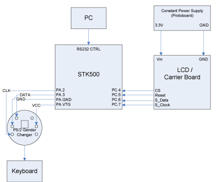
The main pieces of hardware involved in our calculator are an LCD display for showing the user inputs and graphing the output, a keyboard of dynamic entry (text, numbers, and math symbols), and the STK-500 for the Mega32 microcontroller. The LCD was an LCD ordered off Sparkfun.com. The keyboard was a standard PS/2 keyboard. When testing, we used both Dell and IBM keyboards, but since both followed the more common industry standard of scan code set 2, there was never any problem using the keyboards. The STK-500 was the standard classroom board that we have been using all semester. Even though we did not use most of the functions on the STK-500, we opted not to use our own printed circuit board because it was extremely convenient to have some of the indicators on the board for development.
The keyboard presented a bigger challenge then we would have expected. By doing a little research, we knew how the PS/2 keyboard worked. With 6 output pins in the device, only four of them were used: Vcc, ground, clock, and data. The PS/2 keyboard works by supplying power and ground to the keyboard (the recommended values are 5V at 300mA, but we supplied 7.5V at approximately 500mA). Once a key is pressed, the keyboard generates is own clock signal and a data signal that it passes through the respective lines. In order to decode which key was pressed, the host must read the data line on the falling edge of the clock. In all, 11 bits of data are collected per key stroke. The scan code syntax is 1 start bit, 8 data bits, 1 parity bit, and 1 stop bit. The 8 data bits are passed in with least significant bit first, which means essentially that the scan code is "backwards" from what a normal human was expect. In addition, both lines float high when idle (so the start bit is always logic 0 to signal the start of a data stream). The keyboard clock is not an accurate crystal. The published data shows that a keyboard clock cycles approximately 10-16 KHz. This translates to roughly 60-100us periods or an average of 80us. If a key stroke is pressed from for a designated amount of time, the key starts to send repeat patterns to the host (so the key will start to replicated very quickly to the host machine). If the key is released, the keyboard sends a known "break" command to the host (0xF0) followed by the key that was just released. This creates at least 22 bits for the ending sequence of the keyboard. Because we are using our keyboard in a very limited function (all 26 alphabetical keys, both the top-row and keypad numbers, and miscellaneous buttons such as enter, asterisk, divide, period, etc.) we did not deal with any of the "strange" scan code keys (such as break/pause, which has a 64-bit scan code). In addition, we were not too concerned with the fidelity of the scan codes, so we do not worry about the start, parity, and stop bits. Also, since the user should not be pressing more than one button down at a time, we also ignored the break code and its corresponding bits at the end. This essentially leaves us with 8 bits of real data, of which our only task is to flip the bits (to put MSB on the left end of the array and LSB on the right end) and then compared to an array look-up table. The keyboard input was read using a 10us interrupt on the Mega32. The interrupt would poll the keyboard input line (A2 for clock, A3 for data) to check and see if the clock line was low. If the clock line was low, then it would accept the data value on the data line into an array. We polled the line every 10us to over-sample the keyboard on purpose. Because of the variability in the keyboard clock, we would not count on an 80us interrupt to achieve enough accuracy. Because the PS/2 keyboard is a male connector, we used a female-to-female PS/2 gender changer adaptor that changed the PS/2 keyboard connector into a female connector; the adaptor allowed us to easily connect wires to the PS/2 keyboard and to integrate with the STK-500 board.
The STK-500 board has a number of built-in handy devices that our calculator ended up not using. One extremely useful component was the LED array, which we used to detect which state our software state machine was in, in addition to debugging initializing problems. The STK-500 also had an interface with the computer (Hypertrm) via an RS-232 cable. We also used Hypertrm extensively in our initial development, but in the final product, we opted to move everything onto the LCD display to decrease on the number of peripherals and dependencies that the graphing calculator would have. Lastly, another convenience that the STK-500 afforded us was readily available "ports" that we could plug our external devices such as the LCD and keyboard into. Aside from that, the decision not to use a smaller Mega32-only board was that the difference in price ($2 net change) was not a suitable tradeoff. Otherwise, the only real component we used on the STK-500 board was the Mega32 chip.
The software for the graphing calculator was developed mostly from scratch. Aside from the LCD driver and the LCD font set, everything else was developed as the project progressed.
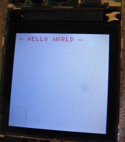
The first thing that we attempted to tackle was the LCD driver. After getting the default multi-color box to appear, we tried to change the colors and size of the box. With several tests, we immediately noticed that the coordinate (0,0) was located in the top left corner of the screen. This coordinate system would cause us many problems because the math needed to scale and zoom became extremely tedious to code, which we realized after several failed attempts. Another piece of software that was borrowed from another person was the LCD font set, developed by Christian Montoya and James Luk in our 476 class. They bit-mapped all of the alphanumeric characters in a 6x6 grid and the characters were quite clear and legible. We chose not to alter their font set, but added our own characters because of the math symbols that we were using. In addition, Christian and James also wrote a comprehensive set of functions for the LCD. The original graphing calculator design was based on their functions, but in the final product, we rewrote our own functions for better functionality and efficiency. The functions that the other group created was better optimized for graphical use, not text display. Creating our own functions allowed us to create several optimizations, such as backspace. Backspace (deleting characters) was achieved by drawing a 6x6 white square to block out any possible letter in that character space. The spacing on the LCD was done by "padding" the left (Lmargin) and top (Tmargin) by 5px. The text was written to the screen and the characters were spaced by 2px between each character (Cshift). Each new line was also 2px between lines measured from the bottom of the first line to the top character of the second line (Vshift). The text is a little bit small with a 6 pixel font, but it allows our LCD to hold a lot of lines of data.
If the user hit enter on the keyboard input, the calculator would try to process whatever was just passed to it. If it was any of the crucial keywords, it would go into a special state machine to take care of the functions. For example, the keyword "graph" would cause the graphing state machine to trigger. If the keyword was "clear", the entire screen would be wiped white, essentially erasing all the data on the screen. The "cursor" would be placed back at the top of the row (5px from the top and 5px from the left). If the user entered a regular equation, the software would pass the equation to a function called doCalculation(). doCalculation() parsed the input string into numbers (int) and mathematical symbols (func). It would evaluate the function and return an answer (int). A sub-function doMath() acted as support for the doCalculation() function. While the doCalculation() function parsed the string, doMath() would perform the actual math crunching. More in-depth, the doCalculation() function took in a 20-element string array. It parsed the first number into a temporary int variable and put the operator into an unsigned char variable titled func. It would then "walk" through the rest of the equation putting numbers that it parsed into a second temporary variable (int). When the second temporary variable was filled, it would doMath() temp1 and temp2 with the gathered function. The answer from doMath() would go into temp1 and the parser would try to find another math symbol and number to put into func and temp2. If it would not find another math symbol, doCalculation() would break and return the final answer from the string calculation.
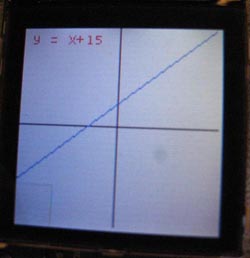
To implement graphing, the user would first have to enter the key word "graph". We created a state machine that collected a number of variables before the graphing would be conducted. First, it took in the equation to be graphed in similar format that the scientific calculator accepted equation inputs. Next, it asked for the x and y scaling indexes and finally, it went into a state titled "GraphReady". In this state, the state machine parsed the input y= equation and replaced "x" with an array filled with x values to be computed. Once the simple string replacements were made, the equation was dropped into doCalculation() which evaluated it as a regular scientific equation. The answer was placed into an array of points to be plotted. The array was 1-dimensional because the actually array index was the x-axis value and the array value was the y-axis value. In this way, we saved ourselves one array and cut down a little on memory usage. Certain limits were imposed on the graphing. For example, if the ymax and ymin values were backwards (if ymax was smaller than ymin), then the state machine would automatically switch the two values. The same applied for xmin and xmax. In addition, if the calculated value for a given x point was greater or smaller than the allowed y tolerance, the value was automatically set to the border value (ymax or ymin). Additional support functions include fixInt() and fixChar(). These functions were to help force typecasting between (int) and (unsigned char). There were frequently compatibility problems switching between the input string (unsigned char) and the output variable (int). The two functions used for loops and just flat-out compared the characters and numbers and outputted the corresponding typecast of the same value.
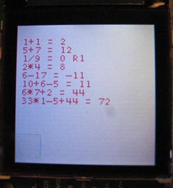
Two additional notes should be made about the calculator. The first is order of operations. Because there is no real parsing built into the calculator, only simple parsing could be performed. In other words, the equations in our calculator are evaluated in a linear, straight-forward basis. The equation 1+1*3 will evaluate to 6 instead of 4 because 1+1 is evalued to 2 first, and then 2*3 evaluates to 6. There were several options to get around this, many of which we attempted but eventually gave up on. The first option was to create a C-syntax parser that would detect for the operand and attempt the mathematical caluclation that way. This proved to be too challenging of a recursive function to write reliably. A second option was to change the calculator into a reverse polish notation calculator. A reverse polish notation calculator has unambiguous syntax (1+1*3 would be inputted as 13*1+) and would automatically take care of order of operations for us. However, it was too difficult to write a reverse polish notation parser for more complex functions because we did not fully understand reverse polish notation ourselves. (For example, we were not sure how to represent 2*5+3*6 in reverse polish notation.) Lastly, another option we tried was to create a reverse polish notation parser that automatically converted a regular string (1+1*3) into a reverse polish notation string (13*1+) and then evaluated it that way. The problem with such a parser was that it was essentially performing the same function as a regular C-syntax parser in regards to order of operation and the effort put into writing such a parser/converter would essentially be the same as writing a regular C math parser and skipping the reverse polish notation step altogether. The final conclusion for order of operations was a sort of "last entry" memory function. If the user typed 1*3 and returned 3, the user could then immediately type "+1" to achieve 4, the correct answer. In this way, we did not ask the user to understand or convert to polish notation. Rather, we are merely asking the user to think wisely about the order of operations because using the calculator to evaluate numbers. It is not too unreasonable a conversion for a human to make, as opposed to converting into reverse polish notation.
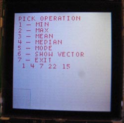
The second special note on our calculator was the statistical analysis function using vectors. If the user typed in the keyword "stats", it would call up the statistical function. It would first prompt the user to enter up to a 5-element vector of numbers, and then it would be able to perform a number of functions depending on what the user asked for. The stats function of our calculator is able to figure out the min, max, mean, median, and mode of a set of numbers. Even if the user entered less than 5 numbers into the array, the calculator would automatically adjust its index boundary and figure out the correct answer.
One last function wraps up all of the special functional keywords for our calculator. The keyword "clear" erased the entire screen and returned the cursor to the top of the page.
The speed of execution of the design was very straight-forward. Despite being a calculator, the majority of the calculations that the microcontroller had to perform were not mathematical. Rather, the majority of the processing power went into parsing strings, gathering keyboard inputs, and outputting to the LCD pixel by pixel. The relatively concurrency of the system seems instant because of how compact the code is. The keyboard is clocked in on 10us intervals, so the total time to gather 11bits of data is about 100us. The keyboard will not accept another input until the main() function outputs the gathered key first, which then comes with a break code and a discarded scan code, for a total of 3 11-bit sets that needs to be collected before another key in inputted. The collection time alone is 330us (11 bits * 3 sets * 10us/bit), but the time to output it to the screen is undefined because it is software dependent on the while(1) loop. However, despite all of the scan codes that are hidden from the user (25 bits out of 33 bits are never used; only 8 bits of scan code are used per key), there does not seem to be any lag or "skipping" of keyboard input, no matter how fast the user types. If the codes get any longer or slower, there might be timing issues with how fast the user can type on the keyboard, but at its current size, there are no noticeable problems.
Because the keyboard is sampling at about 8 times the actual keyboard output speed, there is never any problem with sampling accuracy for the keyboard input. There are, however, accuracy issues with the mathematical and graphing calculations. Because the Mega32 does not support float (whenever we attempted to output float, it would mutilate the number), there was no good way to implement finer values. A division value was reported as its quotient and its remainder. We couldn’t convert a divide number into its decimal form. In the graphing scenario, all of the x-axis values were rounded to the nearest whole number, which caused some slight resolution problems.
Overall, there are no unique safety issues with our product. The graphing calculator takes advantage of a full-sized keyboard, which has been shown to cause Carpal Tunnel Syndrome from extended repetitive use, but we do not foresee any serious long-term, extended, constant use for a graphing calculator. In addition, all power supplies were 3-7V and low current. None of the exposed leads posed any serious threat to the user, even if the user were to complete a circuit and get "electrocuted". (Three volts is not dangerous enough to cause problems.) Our project is completely self-contained and issues no signals or commands that could interfere with other projects. There is no sound involved in our project and thus will not cause a nuisance to anyone around us.
Lastly, we tried to design the calculator to be similar for usability to the TI-calculator series. However, we made some modifications due to some restrictions, mostly from the small size of the LCD because of the budget. In order to compensate for this, we ensured that the contrast was set at a high level and that the font size was increased for easy reading on the eyes. We were not able to find a proper enclosure for the product though, which would be an obvious necessity when marketing the calculator as user friendly.
In retrospect after completing the project, the results did not quite meet all of the expectations that we set forth. After implementing the LCD and keyboard, we did not anticipate the complications that arose when programming both portions of the calculator. On the scientific side, the order of operations proved to be a problem because we were not able to parse the string properly to verify which computations would need to be done first. Conversely, for the graphing side, the math involved to scale and zoom in and out was difficult to output to the LCD based on its conventions. In hindsight, the program could have been implemented differently with a separate parser and more features to compensate for the inability to change graphically. Overall, the functionality was aesthetically pleasing but took longer and cut into the number of total features that could be added.
In consideration of intellectual property, several people must be mentioned that were integral to the completion of the project: Refik Hadzialic for the skeleton LCD display code, Professor Land for displaying characters, and Christian Montoya and James Luk for the original font set. The code written by these people were all released with the protection of the GNU General Public License and Professor Land’s permission. There are most likely no patent opportunities for this project because its similarity to the TI models.
After reviewing the IEEE Code of Ethics, it was clear that no violations were made in the making of this project. As responsible members, we provided a product that is completely safe with low voltages and currents that have no possibility of hurting the user. The only possibilities for conflicts of interest were with reused code, which was verified to be for free use or under the GNU General Public License. There were no temptations or need for reporting unrealistic estimates or accepting bribery; at no point did we manipulate our costs or falsely advertise the abilities of the calculator. As our primary goal, we seriously attempted to create a product that was useful for an appropriate high school student that is interested in mathematics and engineering to further their pursuit of higher education. Throughout the process of the project, we also constantly requested the help and constructive criticism of our peers as well as the TAs to see what features would be most beneficial for our audience. In recognition of their criticism, we set out to make changes to improve our product such as the addition of the keyboard. We also provided advice to other groups to support them in maintaining the code of ethics. Lastly, the calculator was created to be completely fair to our audience of users with careful consideration taken for their safety.
A. Commented Program Listing
A complete listing of the code used in this project is provided in the following three files; each one has comments to explain the logic and functions for the reader to understand.
C. Cost Details
| Part | Cost |
| Standard PS/2 Keyboard | Free |
| PS/2 Gender Changer | Free |
| Color LCD 128x128 Nokia Knock-off | $19.95 |
| LCD Carrier Board | $14.95 |
| STK-500 (with Mega32) | $15 |
| Power supply (3V) | $5 |
| Total | $54.90 |
D. Specific Tasks
Greg Wu worked with all aspects of the LCD ranging from soldering to coding for full functionality with the microcontroller. Albert Liang completed the programming for the PS/2 keyboard and basic math functions. The task of coding the graphing calculator and computing statistics were shared equally between both group members.
E. References