Introduction
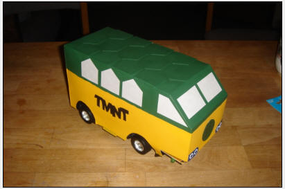
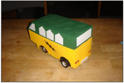
Our project is a battery-powered toy car that is able to follow a path against a background of contrasting color.
The front of the car is fitted with an array of three photosensors, which allows the car to detect the path as well as any turns in the path. Colors that reflect light, such as white, produces a high voltage output from the sensors whereas colors that absorb would output low. By reading the outputs from each of the three sensors, the Atmel Mega32 MCU is able to discern the orientation of the car and whether it is over a straight path or over a turn. The MCU then sends the appropriate logic signals to activate the transistors driving the car’s motors. We use a four-transistor H-bridge circuit to power the front steering motor and a two-transistor half-bridge circuit to run the rear power motors. The H-bridge is able to turn the steering left or right and brake, depending on what logic signal the MCU sends. The half-bridge only drives the rear motor forward and is turned on or off by the MCU.
High Level Design
Back to TopRationale and Sources of the Project Idea
Our project was inspired by robot kits that can be purchased to build line-following robot cars. Often, these kits cost well over $100 and we planned on making one that would cost less than $50. Also, typical line-following robot cars move quite slowly and are solely controlled by the car’s rear motors. We wanted our line-following car to move quickly and to use its front wheels as the turning wheels and its rear wheels solely for driving. A line-following car can also be used in a much larger scale to move hazardous or other materials inside factories or storage houses by following designated paths.
Logical Design
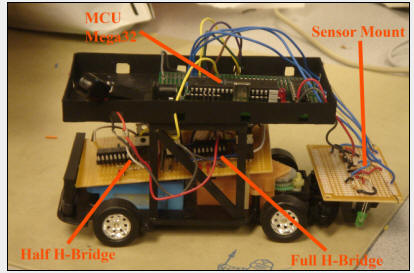
A block diagram of high level design is shown below. The three photosensors communicate to the microcontroller via Ports A.0 – A.2. The half H-Bridge, which controls the rear drive motor, is controlled by Port B.3, the PWM output port. The full H-Bridge, which controls the front turning motor, is controlled by the microcontroller through Ports A.3 – A.6. The PC Board that contains the microcontroller is powered using a single 9V battery. Two separate 9V batteries are connected in parallel to power the motors.
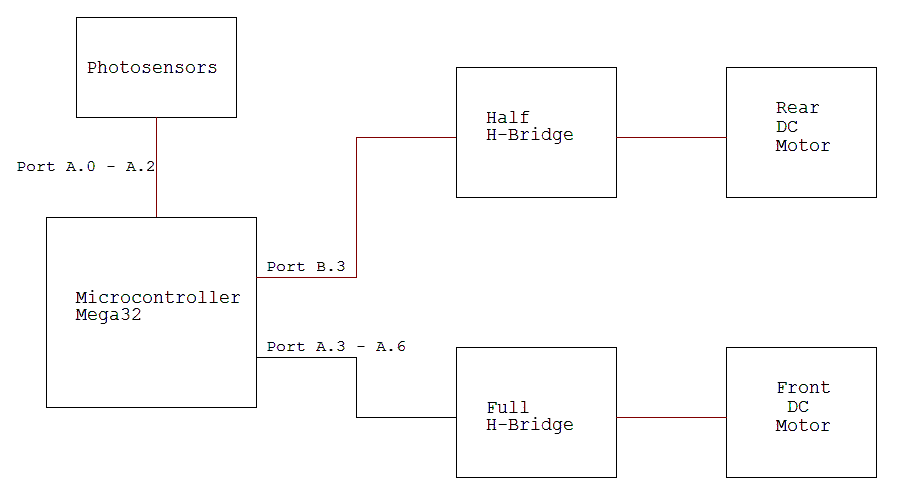
Figure 1: High Level Block Diagram
Hardware Tradeoffs
Due to spacing constraints, we were not able to mount more photosensors than we had previously anticipated. Originally, we planned to have an array of six to eight sensors across the front of the car. More sensors would enable us to detect how sharp of a turn is ahead with various sensor readings. Instead, we could only fit three sensors comfortably on the front of our car and this fortunately was enough to perform the sensing.
Software Tradeoffs
We wanted to sample the sensor readings as fast as possible so that the car will not miss any turns when it is driving fast. However, since we have three sensors and only one analog to digital converter, we had to take turns sampling each sensor and converting it. However, the MCU requires a certain number of cycles to pass before starting each new conversion. Thus we were forced to slow down the speed at which we sample the ADC. Once we slowed down the ADC readings, our car had difficulty sensing turns because it was driving too fast for the sensors to respond. Therefore, we had to slow our car down as well. Originally, in drive mode, the rear motor was constantly on. To slow the car down, we sent a PWM signal to constantly turn the motor on and off. The PWM slowed the car down to approximately half the original speed. Driving slower, the sensors were then able to sense turns in the track.
Relationship of your design to available IEEE, ISO, ANSI, DIN, and other standards
All components used for our project has been approved by the IEEE compliance standards and there are no standards that pertain to our project.
Existing patents, copyrights, and trademarks which are relevant
There are no relevant copyrights, patents, and trademarks for our project. Line-following robots already exist without a patent and our car implementation does not infringe upon any copyright or trademark.
Hardware
H-Bridge Circuit
We implemented a full H-Bridge and a half H-Bridge to control the turning of our motors. Since we needed our front motor to turn both directions for left and right, we connected a full H-Bridge to the front motor, which allows us to run the current in two different directions. Because we did not need our car to drive in reverse, a half H-Bridge was sufficient to control the rear motor. A schematic of our full and half H-Bridges are shown in figures 2 and 3 respectively.
Figure 2: H-Bridge for Turning Motor
The H-Bridge design is essentially four switches, where the switch is a BJT. When the top left and bottom right switches are turned on by a logic high from the MCU, the current will flow from the battery source through the switches and will spin the motor in one direction. When the top right and bottom left switches are turned on, the current will flow the opposite direction through the motor. This opposite direction of current flow causes the motor to spin the opposite direction. When the two top switches are turned on and the bottom two switches are turned off, it creates a short circuit across the motor. This short causes the motor to spin in both directions and hence simulates braking or deceleration. Although we could also stop the car by simply turning off all the transistors, we noticed during testing that there would be a delay when the steering motor turns off. Since we didn't want the car turning more than it should, we added the braking logic so that there would be quicker stop in the front motor. Switches on the same side (left or right) are never turned. If they are turned on simultaneously, there will be a short circuit across the power supply and will damage the circuitry as well as the power source.
Since the motor will be switching on and off in two directions, protection diodes are needed across the collectors and emitters of the BJTs to prevent inductive kickback that could damage the motor and transistors. Fortunately, the TIP102s and TIP107s we chose already had protection diodes built-in so there was no need for external protection diodes. To ensure that the noise generated by the motor does not affect the MCU power and ground, we used opto-isolators to turn on the BJTs. Ports A3 - A6 are connected to the inputs of the opto-isolators, which isolate MCU power and ground from the H-Bridge power and ground. To prevent too much current flowing from the MCU ports into the input of the opto-isolators, 330Ω resistors were connected to them to limit the current. We chose an opto-isolator packaged with four units on a single chip to facilitate circuit population. Each of the four opto-isolators for the full H-Bridge is connected to the base of one of the four BJTs. Figure 2 shows which MCU ports are connected to which BJT gate.
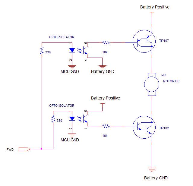
The half H-Bridge was constructed much the same way except it only used one NPN, one PNP, and two opto-isolators. Only one control signal is required to turn both BJTs on and thus turn the motor on. We did not implement braking for the rear motor because there was no need for sudden braking. The input signal to the BJTs for the rear motor is connected to Port B.3 on the MCU. The schematic of the half H-Bridge is shown below in figure 3.
Figure 3: Half Bridge for Rear Motor
H-Bridge Testing and Results
Initially, we tried using NMOS transistors to construct our H-Bridge. In the MOSFET H-Bridge design, the drains of the top two transistors were connected to the positive end of the battery and sources of the bottom two transistors were connected to the negative end of the battery. The sources of the top transistors were connected to the drains of the bottom transistors and the motor was placed between these two nodes. We applied 5V to the gates of the top left and bottom right transistors to supply voltage to the motor. However, the across the motor was consistently around 1V no matter how much voltage we supplied to the H-Bridge. We had first supplied 5V to the H-Bridge with only 1V across the motor. We increased the voltage to the H-Bridge to 12V and the we still measured 1V. We then realized that 5V was insufficient to put the switching NMOS into saturation. Instead, the NMOS transistors were still in the linear region and thus limited the current flow and thus limited the output voltage. We raised the input voltage to the NMOS gates to 7V with a 5V supply to the H-Bridge. This time, the NMOS transistors were in saturation and the H-Bridge gave an output voltage of 4.6V. Although we had gotten our MOSFET H-Bridge to work, the 7V needed to turn on the transistors posed a problem since the MCU ports could only provide 5V when turned high. Also, when we applied 7V to the MOSFETs, they became very hot and this would pose an unacceptable risk to the user. Of course we could use heat sinks but that would increase costs and make construction more inconvenient.
Due to this problem, we decided to try using BJTs instead of MOSFETs for our switching transistors. The two high side transistors were PNPs and the two low side transistors were NPNs. We picked TIP102s for the NPNs and TIP107s for the PNPs because they were both Darlington configurations, which have high current gains, and they had protection diodes built-in. Furthermore, these BJTs came in TO-220 packages which are easy to use on the protoboard. The 10kΩ resistor between the output of the opto-isolator and the base of the BJT limits the current that goes to the gate. According to the TIP102 datasheet, the max base current is 1 A but we decided to be more cautious and use a large resistance value.
We tested the BJT H-Bridge by applying 5V to the top left and bottom right opto-isolators and also supplying a separate 5V to the H-Bridge power supply. This time, the voltage across the motor was approximately 4.6V so we were able to see at least what we were supplying to the H-Bridge across the motor. We then connected the H-Bridge to the motor, and the H-Bridge successfully powered the motor. Since we wanted our car to run without being connected to a power supply, we decided to power the H-Bridges using batteries. We initially thought of using four AA batteries in series to provide 6V to the H-Bridges. However, when we tested the car by supplying 6V to the H-Bridges using the power supply, the car had difficulty fully activating the turning and driving at the same time. The two motors needed at least 7V for them to run simultaneously without problems. Therefore, we decided to power the H-Bridges using a 9V battery. We initially tested running our car off of one 9V battery but the car had difficulty driving because the battery was not providing enough current. Thus, we connected a second 9V battery in parallel to supply the H-Bridge with more current. With increased current, the car ran normally.
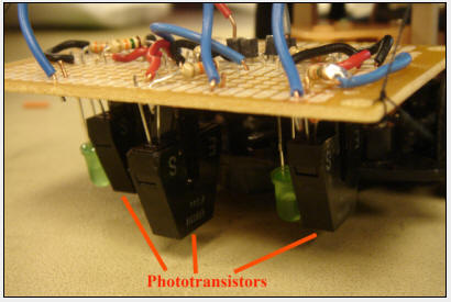
Phototransistors
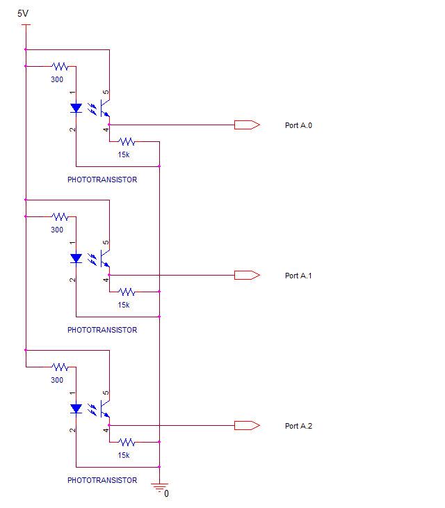
To detect black lines on a white surface, we chose the QRB1114 phototransistor for its low cost and easy implementation. The QRB1114 is a package consisting of an LED and a phototransistor BJT. The transmitter is the LED, which emits infrared light that reflects off a surface. The amount of reflected light is measured by the BJT, which sinks more current to ground if it detects more reflected light. White surfaces reflect light well whereas black absorbs most of the light and thus very little is reflected back to the receiver. A schematic of the sensor circuit is shown below in figure 4. Note that the schematic for the photosensors is somewhat misleading. The light from the LED does not directly activate the BJT, which is what happens in an opto-isolator. Rather, the light reflects off a surface and activates the BJT.
Figure 4: Photosensors
We connected 330Ω resistors to the input of the diodes of the photosensors to limit the input current to 13mA from the 5V power supply. It prevents too much current from entering the diode and destroying it. At first we tried using 1kΩ pull-up resistors between the collector and 5V power source. We then scoped the output of the photosensor to see its sensitivity and voltage reading when we placed white or black paper over it. Unfortunately, the phototransistor output fluctuated from a few hundred mV to about 3V. Under black, the phototransistors output should consistently be very low. However, it seemed like the phototransistor was detecting sudden movement more than color. When we switched from white to black, the voltage reading would suddenly flicker from high to low for a few seconds and then it would return back to a high reading even though black was still placed under the sensors.
We believe the mistake can be explained as follows: The figure to the far left shows a BJT connected to a pull-up resistor. Vout = Vcc – Ic*R. If the sensor is over black paper, Ic will be small and Vout will be closer to Vcc than we want. This accounts for the larger than expected reading we observed. Therefore, we decided to switch to using a pull-down resistor as opposed to a pull-up resistor. The figure to the near left shows that Vout = Ie * R. In this case, the smaller current would correspond to a smaller voltage. We connected a 10kΩ resistor in series to a 10kΩ potentiometer between the emitter and ground on the output of the phototransistor. We used a potentiometer instead of a static resistor to adjust the pull-down resistance accordingly to the ambient light. We tested the circuit and it worked better than the pull-up configuration. We adjusted the potentiometer until we found the optimal setting.
The pull-down resistance of the 10kΩ resistor and potentiometer was about 15kΩ total. This time, the sensors provided consistent outputs with little fluctuations. Under white, there was maximum reflectance so the sensors output approximately 3.9 - 4.1V. Under black, there was maximum absorbance of light so the sensors output approximately 200 - 250mV. There was a large voltage difference between white and black readings to enable easy differentiation between the two colors. We then connected the senor output to Port A.0 of the microcontroller and tested the sensor using the analog to digital converter with the internal 5V reference. The conversions were stored in Ain; for black, Ain values were around 10 - 15, and they were around 190 - 210 for white. We also determined that the sensors performed better under brighter lighting conditions. Since the sensors are mounted on the bottom of our car, we decided to add LEDs near the sensors to illuminate the ground. We placed an LED next to each sensor. The LEDs were again current limited by placing a 330Ω resistor in series with the 5V power supply.
We chose to use three phototransistors configured in the shape of a V with the middle sensor out in front of the left and right sensors. We decided to use three sensors because the sensors were voluminous and we simply could not mount more on our small car. We decided to use a V configuration to help the car detect turns in the course. With the middle sensor out in front, it will detect white first. Then, the left or right sensors will detect if the course turns or not.
For our final version of the sensors, we soldered three phototransistors in a V configuration onto a small protoboard. We also soldered three green LEDs adjacent to the phototransistors. The entire sensor suite, including the LEDs, was powered off of Vcc from the mini STK board.

Software
The program to run the car consists of a portion to sample data from the photosensors and a portion which uses that data to send the right logic signals to the circuit controlling the motor. The program cycles back and forth between reading the sensor’s output and moving the car.
Sampling Data from Photosensors:
We use the Mega32 ADC to read the output of each of the three sensors; the outputs are fed into the first three pins of Port A. The program sets up the ADC so that it uses AVCC as the voltage reference source, which is the MCU’s internal 5V reference. The program also left-adjusts the result in the ADC data register and reads only the first 8-bits. With the exception of using AVCC rather than AVEC as the voltage reference, our setup is the same as that of the simple ADC code provided to us by Professor Land for a number of the semester’s labs.
A simple state machine, running continuously in the function main, collects data from each sensor and stores the values in variables that will be used to inform the car’s motion. In each state, we read from the ADC data register once before moving to the next state. We sweep through the right, left, and middle sensors in that order before cycling back to read the right one. The first command in each state is to read from ADCH, the ADC data register which contains the values of the conversion. Then, the program changes which pin to read from by adjusting the appropriate data bits in ADMUX. Before transitioning to the next state, the program re-enables ADSC to begin another conversion. It is important to change the pin selection first before enabling the conversion; flipping the order of these commands means the ADC will finish a conversion first before switching channels. This leads to unintentionally reading from the same channel twice.
Figure 5: State Machine for Sensor
Issues: Timing issues posed some problems when writing this portion of the code. Each conversion of the ADC consumes 13 ADC clock cycles (25 clock cycles for the first conversion after enabling the ADC). Reading from the ADC data register or beginning another conversion before 13 clock cycles have finished may lead to incorrect readings. Such errors arose when we tested an earlier version of our program. We placed one sensor over a dark strip of paper while placing the other sensors over white piper. By printing the value in ADCH for each sensor to Hyperterm, we would be able to determine if our ADC setup was correct. We noticed that some of the values that we would expect from one of the other sensors were showing up along with values from the sensor being tested. In that program, we set the MCU clock with a prescaler of 64, while running the ADC at a prescaler of 128, and read ADCH immediately after enabling a new conversion. Thus, there did not seem to be enough time for the conversion to complete itself before we read from the register so we were getting data from previous readings. This explains why we saw high values from the sensors over white paper interspersed with the low readings from the sensor over dark paper.
A simple counter helped clear this problem. We put the counter in a timer2 overflow ISR. With the MCU clock at a prescaler of 64, the counter would increment every 64/16MHz x 250 = 1 msec. Within each state, we would wait until the counter increments before reading from ADCH and starting another conversion. This millisecond buffer provides enough time (much more time than is needed actually) for one complete conversion.
Moving the car:
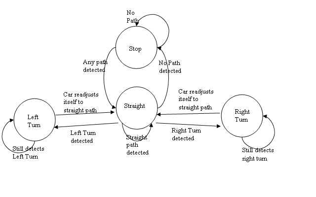
After sampling the sensor output, the program enters another state machine which controls how the car should move. The first state, state stop, checks the values from the variables that store the readings from each sensor. Through testing, we observed that when the sensors output high, as it does when placed over white paper, the ADC reading is never below 80. When they output low, as it does over dark paper, the ADC reading is never above 40. If every sensor is giving a reading above 80, then the car is over white paper and does not move. If any one of the sensors reads below 40, then the program turns on the rear motors first and then transitions to state straight.
We use the timer0 PWM to power the rear motors. Fast PWM mode is enabled and the compare output mode is set to clear OC0 when the timer0 counter equals OCR0, and to set OC0 at top. With the timer0 clock set at a prescaler of 256 and OCR0 set to 128, we will get a PWM signal with a period of 256/16MHz x 256 = 4 msec and a duty cycle of 50%. The PWM waveform is output through port B3, which is connected to the gate of the two BJTs that turn on the rear motors. Therefore, the rear motors turn on and off in equal measure.
While the car is moving, the program returns to reading the sensors. A full sweep of the three sensors reveals any changes in the course of the path. In general, a low output from one of the two non-center sensors and a high output from the other reveal a turn. For left turns, the program sends a high signal to transistors 3 and 4 while for right turns, transistors 5 and 6 turn on. Immediately afterwards, the program transitions into state left_turn or state right_turn depending on the turn. In either state, if the sensors detect that the middle sensor is not over a path, the car will continue to turn. As a self-adjusting measure, the program checks if the other non-centered sensor every outputs low. If so, then the car has turned too much in one direction and will start to turn in the other direction. Once the middle sensor reads low again, the car will stop the steering motor and return to state straight. If all three sensors read high, the program will turn off the PWM and transition to state stop.
Figure 6: State Machine for Car Movement
Issues: We had a number of issues reconciling how we wanted the program to work with the mechanics of the toy car. The car’s speed became the first issue we encountered. In an earlier version of the program, we sent the motor a constant logical high signal. During testing, we noticed that the car would travel so fast that it would overshoot turns. The sensors would detect the turn but by the time the program could initiate a turn, the car had already driven off the road and would stop. At Professor Land’s suggestion, we instead used the PWM to drive the rear motors. This slowed the car to half its original speed, which is not surprising considering our PWM waveform’s 50% duty cycle.
Slowing the car allowed more time for the program to react to turns but the car’s inherent turning radius is fairly wide. The car was likely to go off the road and stop even at the slower speed. The program addresses this by initiating a turn first and then waiting 1.5 seconds before reading the sensor data again. The car will therefore continue to turn during the delay even if it has gone off the road; this hopefully gives the car enough time to readjust itself to the course.
 car will be moving
straight at an angle to the road, the left sensor will go over and the
middle sensor will go off the track. This tells the car to make a left
turn. The car will continue to adjust itself in this wobbling manner,
although each time the angle at which it comes into the path is
reduced. Therefore, we found that the path after a turn should be
sufficiently long to allow for this adjusting.
car will be moving
straight at an angle to the road, the left sensor will go over and the
middle sensor will go off the track. This tells the car to make a left
turn. The car will continue to adjust itself in this wobbling manner,
although each time the angle at which it comes into the path is
reduced. Therefore, we found that the path after a turn should be
sufficiently long to allow for this adjusting.