ECE
476 Final Project
Retractable
Alarm Clock (RAC)
Colleen
Carey, Vincent Zou

Index:
1 Project Concept
1.1 Motivation
1.2 Introduction
2.1 Hardware Block Diagram Overview
3 Hardware
Components
3.1 motors
3.2 LEDs
3.3 Switches
3.4 Speakers
3.5 Emitter
Follower
3.6 optoisolator
4 Software
Design
4.1 DDS
4.2 Timing
5 Designs
and Testing
5.1 Design
Flow
5.2 Challenges
6 Packaging
6.1 Retractable
Cord
6.2 Motor
box
6.3 Alarm
case
7 Cost

1.1 Motivation:
Alarm clocks are
essential in almost everyone’s daily life. For most of us, we start our day to the sweet noise of our
alarms. While some people wake up
instantaneously to the first chirp of an alarm, some struggle everyday to get
out of the bed. The Retractable Alarm Clock is the next generation alarm clock
that combines both active alarm feature and penalty system that trains the
users to wake up to the alarm over time. The clock in this projects consists of
a head unit that is to be hanged on the ceiling above the bed and has a
retractable snooze button which hangs to reachable height above the bed. When
the user snooze the alarm, the snooze button moves up, promoting the user to
physically get up and to snooze the next time.
1.2 Introduction:
By using an ATMega32
chip, the alarm clock can generate different alarm sounds. The time is
displayed on LED lights. A
customized snooze button is made to accommodate the movement of the retractable
cord powered by a small dc motor. The alarm gradually increases the loudness to
wake up sleepers gently. To prevent the sleeper from falling asleep to the
monotonic sound of alarms, our alarm varies the frequency every 12 chirps.
2 High Level Design:
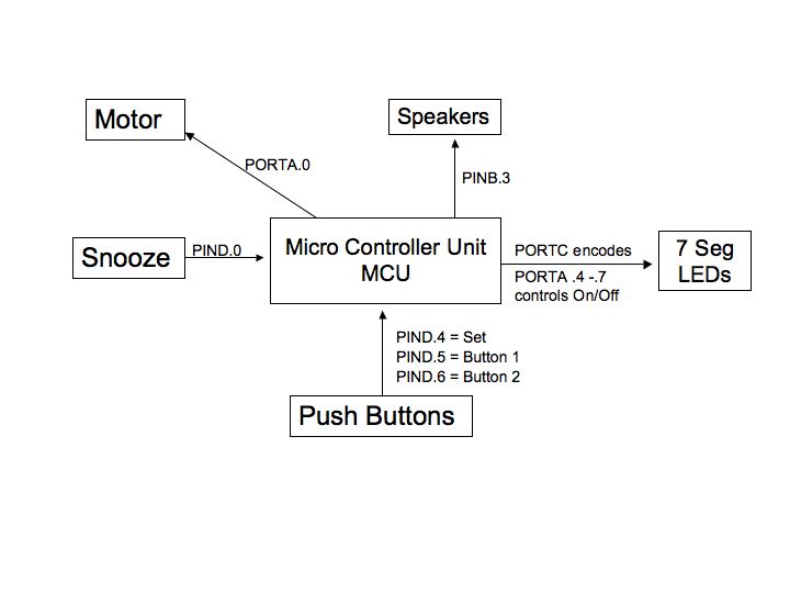
2.1 Hardware Block
Diagram Overview:
The following block diagram
describes our basic hardware layout:
2.2 Software State
Diagram:
The following block diagram
describes our basic software layout:
3. Hardware Components:
3.1
Motors:
For this project, we
tried five different motors. The
fan motor used in Lab 5 does not provide the required torque. The stepper motors that were available
in the lab require too many control lines. Because we have limited ports off the ATMEGA32, we would
have to have used a multiplexer.
Also, the only function that we require the motor to do is to spin in
one direction and thus using a stepper motors seems like a waste if its
potential. We then found a broken
electrical toothbrush and took the motor out of it. The electrical toothbrush runs on a 1.5V AA battery. The
entire circuit that we build is based 5V so to use the motor from the
toothbrush we would have had to step down the voltage before it entered the
motor. However, by doing so, we
also decrease the voltage going in to the 4N35 chip that is used to control the
motor. The voltage drop across the
4N35 is about 0.7 V, when running on a 5-12V, this drop seems ignorable, but if
a 1.5V is applied, the drop is almost half of the voltage and thus will not
power the motor. We then ordered a 9V DC motor from All Electronics, however we
did not use it because it draws 1.35 amps, and is not suitable for our circuit. We also acquired a fourth motor from
another group that was not using it.
The motor was not new and had several connection issues originally. Once we got it working we found that it
heats up the BUZ73 very fast and drains the battery dry in just a few
minutes.
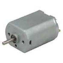
So after exploring all
options, the motor we finally decided to use is a +5V DC motor that was ordered
from Jameco (PIN231802) that came in later than we expected. The motor requires around 0.15 amps to
operate and has a reasonable battery life. This motor is brand new and has no
connection problems. The motor
still heats up the 4N35 chip but it is not significant because we only run the
motor for less than one second at a time, so the heating problem can be
ignored.
3.2
LEDs:
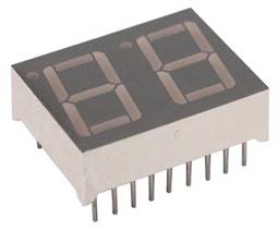
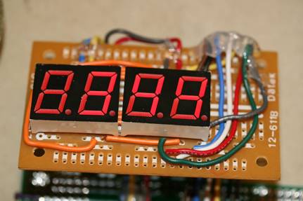
Since it is an alarm
clock, the user needs to be able to read the time at night from a reasonable
distance. A lighted LCD is too hard to read even though it would be much easier
to integrate. We used four seven segment displays. Under different settings,
the display will show the Current time, Alarm set time, Current Date, and
Current Day of the Week. Once the set button is pressed, the display settings
change in order to show the current setting on the LEDs. This means that if the set button is
pressed once, the LEDs will show the month and date. Pressing the set1 and set2 buttons will change the month and
date, respectively. Once the set
button is pressed again, the current time is displayed. Pressing the set1 and set2 buttons will
change the hour and minute, respectively.
One more press of the set button will change the LEDs to display the
current day of the week. Pressing
the set1 will increase the day and set2 will decrease the day. Pressing set a final time will return
the display to the current time after all settings are made.
To power all four LEDs
at all times requires a considerable amount of current and drains the
battery. Also, if we wanted to
code each 7-segment display individually, 36 control lines and pins would be
required. Due to the above two
limitation, we could not control individual LEDs separately. To solve this
problem, we wired all the LEDs in parallel to the same output pins. This method required each LED
display to have its power controlled separately. The total configuration required 12 pins. By precisely timing the refresh rate
and on and off of the individual LEDs, we can flash the 4 LEDs in sequence and
change the display between each flash. Human eyes can’t detect the change as long
as it flashes at a reasonable rate. We light each LED for 5ms before switching
to the next LED. To the viewer,
the flash is not detectable.
Speakers and Motors drain a
significant amount of current from the battery; to run them all at the same
time results in overheating Buz73 and significant dimming of LEDs. To solve
this problem, we cycle through the 3 components the same way we flash the
LEDs. When the Alarm goes off, LED
displays flash every 5 ms and cycle 40 times before the signal is sent to create
a beep at the speakers. Once the
signal is sent the LEDs turn off until the speakers are silent. Also, when the snooze button is
pressed, the motor turns on and both the beeping and LEDs turn off.
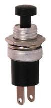
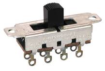
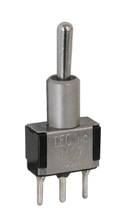
3.3
Switches:
3.4 Speakers:
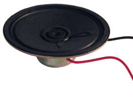
The Alarm clock has two speakers so it looks
symmetrical. Only one speaker is
need to produce an audible sound but two sounds better. We use two 8 Ohm,
0.25W, and 21/4-inch speakers from AllElectronics.com. Unlike the speakers from the TV, those
we have do not have built in amplifiers. The output from PINB.3 is too weak to
power the two speakers so we built an emitter follower to boost the output of
the speakers. Because of the extra circuitry that we added, some noise is
produced. Since we only need the sound to be a sign wave of some kind, the
quality of the sound it produces is very acceptable.
3.5 Emitter Follower
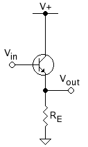
Voltage Gain:
![]()
Current
Gain:
![]()
Input
resistance:
![]()
Output resistance:
![]()
gm
is the transconductance in siemens, calculated by , where:
![]() is the quiescent collector current (also
called the collector bias or DC collector current)
is the quiescent collector current (also
called the collector bias or DC collector current)
![]() is
the thermal voltage, calculated from Boltzmann’s
constant, the charge on an electron, and the transistor temperature in kelvins.
At room temperature this is about 25 mV.
is
the thermal voltage, calculated from Boltzmann’s
constant, the charge on an electron, and the transistor temperature in kelvins.
At room temperature this is about 25 mV.
![]() is the current gain at low frequencies
(commonly called hFE). This is a parameter specific to each
transistor, and can be found on a datasheet.
is the current gain at low frequencies
(commonly called hFE). This is a parameter specific to each
transistor, and can be found on a datasheet.
![]()
Rsource
is the thevenin equivalent source resistance.
To maximize the gain, we used a 10K for RE. The Speaker is
turned on monetarily and does not over heat.
3.6 Optoisolator:
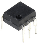
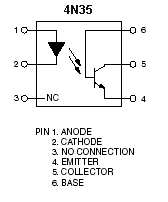
The
Motor is separated from the MCU through an Optoisolator (4N35). The Motor draws
a significant amount of current and it is most safe if runs separately.
4 Software Design
4.1 Alarm/DDS:
Once triggered, the alarm can be only turned off by pressing
the snooze button or shutting off the RAC. If untreated, the alarm will only
sound for a max of 10 mins to prevent battery waste.
The alarm sound consists of:
15
sec of regular alarm,
Pronounced
Day of the week and Date. (i.e. today is Friday, April 27th 2007)
15
sec of a second alarm sound with higher frequency
15
sec of the third alarm sound with an even higher frequency
15
sec of the fourth alarm sound with very high frequency
Repeat the process for 5 mins
After
much thoughts and consideration, we found that the most annoying and effective
alarm sound to be the cricket calls from Lab two. So the DDS codes are based on
the codes and programs that we used in the Cricket call synthesizer in
laboratory assignment 2. The PWM signal will be sine wave bursts
generated using amplitude modulated Direct Digital Synthesis (DDS) technique.
This is the most complicated part of this lab. A cricket call may be very
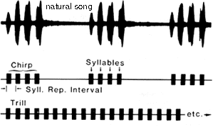
complex, but we will limit ourselves to the following form.
1. A call is made up by repeating indefinitely a
chirp and a silent period. If the duration of the silence is zero, the call is
referred to as a trill.
2. A chirp is made up of a certain number of
syllables with specific duration and repetition interval.
3.
A
syllable is made up of a sine wave burst at a certain frequency. The burst
starts at low amplitude, which increases quickly to a maximum, sustains the maximum
amplitude until just before the end, and then decreases amplitude to zero.
to
create a simulated cricket song, we use sine waves. To generate a sine wave we
use the function sineTable:
for
(i=0; i<256; i++)
begin
sineTable[i]
= (char)(127.0 * sin(6.283*((float)i)/256.0)) ;
end
Now
to make the cricket call smooth, we used an amplitude modulation to envelope
the sine wave by creating a 4 ms gradual rising slope and 1 ms drop at the end
of the chirp. The original code will only generate continuous chirps and
needed to be modified to generate silence periods and repeat intervals.
To do this we used while loop and for loops.
1. We first created a timer that counts every ms
and a syllable counter that counts every time a syllable has been fully
produced.
2. We then enter a while (1) loop to keep the
signal generation continuous.
3. Then we check if time has exceeded the repeat
interval and if the counter has completed all the syllables. If neither
condition has been satisfied we execute the for loop, ram up 4 ms, generate
full signal for a specified length and ram down in 4 ms. This will generate one
more syllable.
4. We keep running the for loop until all
syllables have been generated.
5. Then we silent the song and keep the time
running for a specified period of time. (chirp_silence
-syllables*repeat_int will give the silent perios).
4.2 Timing
Because we use timer0 to control our clock and the dds
portion, we have the prescalar set to 0, so the clock is free running. We record 1ms every 62 counts of the
clock. We then increase the value
of minutes every 60,000ms. From
the value of minute we calculate hour, day, month, and date. This value will be accurate to
the accuracy of the crystal, which is 1 part per million.
5 Designs and Testing
5.1 Design Flow
Vincent was responsible mainly for hardware and Colleen did
most of the coding. We designed and tested each component separately and put
all of everything together at the end.
The Motor took a fair amount of time to set up. See the Motor section. The
LEDs also gave us some problems because we had to figure out the exact flash
rate for it to look like all four LEDs were continuously on. The circuit for the speakers was fairly
simple but we tried to use an amplifier to boost the output. At the end we
decided to use Emitter Follower. Combining the motor, speakers, and the LEDs
consumed a lot of our time because the 9V battery is very weak to power all of
them at the same time. Because the alarm clock requires all three functions at
the same time, we have to switch between the three at a fast enough rate so the
user does not notice.
5.2 Challenges
1. Motor
strength:
Originally what we wanted to have the entire alarm unit hang
from the Ceiling and have it all move up as snooze button is pressed. The entire
unit weighs too much to lift in this way.
This requires too much motor strength and too much power. So to solve
this problem we have a single retractable snooze button that will be pulled up
once the user snoozes the alarm.
We build a great box to have the gear ratio 4:1 at this rate the speed
is a little slow but we have enough power to overcome the weight of the
button.
2. Speaker
Loudness:
Certain chirp setting generates a very low sound. With
syllable set to one or five, the loudness decreases to one fifth of those other
setting for no obvious reasons. Instead of treating this as a challenge, we use
this towards our benefit. Sleepers are usually annoyed by sharp alarm sounds
and studies shows that gradual increase of loudness is more efficient to wake
them up. So we set the first
chirping sequence with syllable one and create low amplitude and then gradually
increasing it. We alternated the frequency of the alarm clock so user does not
get use to the monotonic sound and interpret it as a constant white noise and
fall asleep to it.
3. Voice
generation
In our original design we have a voice generation function
that will announce the Date and Day. We collected all the voice data and tried
them out in a separate voice code. Everything works well separately but when we
integrate them in the alarm code, things got weird and nothing works. We ran
out of time at the end to fix this problem.
6 Packaging
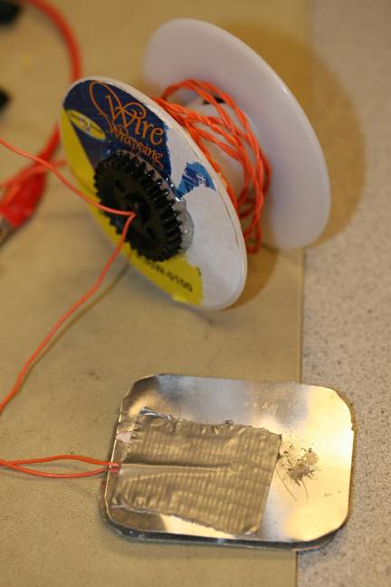
6.1 Retractable Cord
We made the retractable cord with metal plates with a wire
attached to each of them.
One plate is set high and when the two are in contact, the second plate
will be set high.
6.2 Alarm
Case
The motor is not powerful enough directly pull up the snooze
button. So we step down the gear ration to 4:1. So 4 full turn of the motor
produces 1 full turn of the spindle.
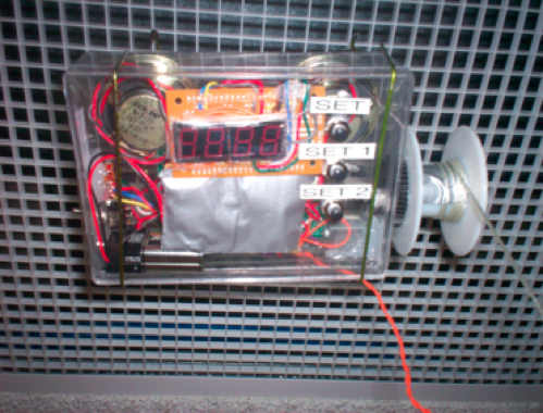
6.3 Alarm case
The Alarm case is made of clear plastic. We found the box in the
wastebasket. In order to add all
of our hardware we had to create several holes for the buttons, switches, and
speakers.
7 Cost
Cost:
|
Item |
Unit Price ($) |
Unit |
Total |
|
ATMEGA 32 Chip |
8.00 |
1 |
8.00 |
|
Custom PC Board |
5.00 |
1 |
5.00 |
|
5V DC motor |
3.24 |
1 |
3.24 |
|
Small Solder
Board |
1.00 |
1 |
1.00 |
|
Speakers |
1.50 |
2 |
3.00 |
|
9V Battery |
2.00 |
1 |
2.00 |
|
Push buttons |
0.05 |
4 |
0.20 |
|
7 seg LEDs |
free |
4 |
0.00 |
|
Gears |
0.2 |
2 |
0.4 |
|
Total |
|
|
22.64 |
8 Ethics
Our Project is an extension and collection of many labs that
were completed during the semester. Many circuit are similar to those that we
built during the class. However, everything has to be modified and customized
to work with our design requirement.
Professor Bruce Land provided many useful codes that proved to be very
helpful. Also, many of the
diagrams used in this report are on the course website, from different labs.
Much credit has go to our beloved TAs for their consistent help. Most of our parts and components are
gathered from the wastebasket and are not counted toward our cost table. Before
the project, we researched the concept of motorized alarm clock and found
several different designs. None of the designs that we found have any data
sheets or instructions on how to build them. So even that the concept of a
motorized alarm is not groundbreaking, building one still requires considerate
amount of high-level and detailed design and testing. All the actions that we took designing this project are
consistent with the IEEE Code of Ethics.
9 Conclusion
The project lasted for four weeks. In these four weeks, we
explored many topics in Microcontrollers ranging from programming and software
to amplification, power regulation, and optoisolators. Most of the functions
are completed according to our timetable.
It is very satisfying to design a product and build every part of it and
to see everything work together.
We had many trials along the way, so this project has helped us to
really understand much of what we have learned in all of our courses at
Cornell. In order to
configure and debug our code and hardware we had to use knowledge from almost
every course we have taken up to this point. As graduating seniors, this project has been a great end to
our Cornell education, as we truly had to apply all of our knowledge.
//******************************************//
// //
// Final
Project //
// Colleen
Carey & Vincent Zou //
// Wednesday
4:30-7:30 //
// final_proj.c //
//
//
//******************************************//
#include <Mega32.h>
#include <math.h>
// for sine
//timeout values for each task
#define t1 75 //
time for debounce
#define t3 20
// time for button check
#define t4 25
// time for
display
#define t5 350
#define begin {
#define end }
#define minute 60000 //
one minute
#define countMS 62
//
ticks/mSec
//define setting states
#define set_normal 1
#define set_month_date 2
#define set_hour_min 3
#define set_day 4
#define set_alarm 5
//define debounce states
#define no_push
1
#define maybe_push
2
#define push
3
#define maybe_nopush 4
//the task subroutines
void debounce(void); // debounces
void clk_display (void);
// controls clock settings
void update_time(void); //
update time
void initialize(void); //
initialize everything
void snooze(void);
void motor(void); //
runs motor
void decode(void);
void alarm_sound(void);
unsigned int push_flag;
unsigned int time, time1, time2, time3, time4, time5; // timeout counters
unsigned char set_state, push_state; // switch statements
unsigned int numb_set_pushed;
unsigned int alarm, alarm_flag, alarm_count,
snooze_count, alarmSet;
unsigned int c, i, MotorOn;
//define dds variables
unsigned long accumulator @0x2f0;
unsigned char highbyte @0x2f3; //
the HIGH byte of the accumulator variable
unsigned long increment;
char sineTable[256] @0x300; // need loc to avoid
glitch
char amp, count;
unsigned int chirp_silence; // chirp+silence time
unsigned int syllables; //
number of syllables
unsigned int syllable_time; // syllable duration
unsigned int repeat_int; // repeat interval
unsigned int burst_freq; // burst frequency
unsigned int counter; //
syllable counter
int display_1, display_2, hour, day, month, date, year,
alarm_hour, alarm_min, snooze_int; //
system time variables
int led1, led2, led3, led4, chirp_count, snooze_flag,
alarm_set_mode;
int Min;
//**********************************************************
interrupt [TIM0_OVF] void sgen(void)
begin
//the
DDR code and scaling
accumulator
= accumulator + increment ;
OCR0
= 128 + sineTable[highbyte] >> amp ;
//generate
rising amplitude
//
62 counts is about 1 mSec
count--;
if
(0 == count )
begin
count
= countMS;
time++; //in mSec
if (time1 > 0) --time1; //timer
1 for debounce
if (time2 > 0) --time2; //timer
2 to count 1 minute
if (time3 > 0) --time3; //timer
3 for updating
if (time4 >
0) --time4; //timer
4 for clock update
if (time5 >
0) --time5; //timer
5 for push buttons
if (c > 0)
--c; //timer
for motor
end
end // end interrupt
//**********************************************************
// main
//Entry point and task scheduler loop
void main(void)
begin
initialize();
//main task
scheduler loop
while(1)
begin
//1ms clock
if (time1 == 0)
begin
debounce(); //
debounce runs every 50ms
end
if
(time2 == 0)
begin
update_time(); // system time updates
time every min
end
if
(time3 == 0)
begin
time3
= t3;
if
(~PIND.6 == 0) //
check if snooze button is pressed
begin
snooze_flag
= 1;
snooze();
end
if
(~PIND.0 == 0) // check if the alarm
is on
begin
alarmSet
= 1;
end
else
if (~PIND.2 == 0) //
check if alarm is in set mode yellow
begin
alarm_set_mode
= 1;
end
else
alarmSet = 0;
end
if
(time4 == 0)
//
reset display counter
begin
time4 = t4;
end
if
(time5 == 0)
begin
decode();
end
if
((alarmSet == 1) && (alarm_hour == hour))// check if alarm is set and =
to current hour
begin
if
(snooze_flag == 0)
//
check if snooze button is pressed
begin
if
(alarm_min == Min)
//
check if alarm is = to current min
begin
alarm_flag
= 1;
// set temporary alarm_flag
alarm
= 1;
// set flag to leave alarm on for 3 min
end
else
if ((alarm_min == Min-1) && (alarm == 1))
alarm_flag
= 1;
// reset flag after a minute of no snooze press
else
if ((alarm_min == Min-2) && (alarm == 1))
alarm_flag
= 1;
// reset flag after two minutes of no snooze press
if
(alarm_min == (Min-3))
begin
alarm_flag
= 0;
// turn off flag after three minutes of no snooze press
alarm
= 0;
// turn off 3 min flag
end
end
end
if
(snooze_flag == 0)
clk_display();
// clock display runs
end
end //
end main
//**********************************************************
// Clock Display
void clk_display(void)
begin
if (~PIND.2
== 0)
begin
display_1
= alarm_hour;
display_2
= alarm_min;
end
else if (push_flag == 1)
begin
if
(numb_set_pushed == 1)
begin
display_1
= month;
display_2
= date;
end
if
(numb_set_pushed == 2)
begin
display_1
= hour;
display_2
= Min;
end
if
(numb_set_pushed == 3)
begin
display_1
= 0;
display_2
= day;
end
if
(numb_set_pushed == 4)
begin
display_1
= hour;
display_2
= Min;
end
end
else
begin
display_1 =
hour;
display_2 =
Min;
end
//
Declare LED 7-segment display parameters
//LED
1
if
((display_1 >= 0) && (display_1 < 10)) // display 0
led1
= 0xff;
if
((display_1 >= 10) && (display_1 < 20))
// display 1
led1
= 0x9f;
if
((display_1 >= 20) && (display_1 < 24))
// display 2
led1
= 0x25;
//
LED 2
if
((display_1 == 0) || (display_1 == 10) || (display_1 == 20)) // display 0
led2
= 0x03;
if
((display_1 == 1) || (display_1 == 11) || (display_1 == 21)) // display 1
led2
= 0x9f;
if
((display_1 == 2) || (display_1 == 12) || (display_1 == 22)) // display 2
led2
= 0x25;
if
((display_1 == 3) || (display_1 == 13) || (display_1 == 23)) // display 3
led2
= 0x0d;
if
((display_1 == 4) || (display_1 == 14) || (display_1 == 24)) // display 4
led2
= 0x99;
if
((display_1 == 5) || (display_1 == 15)) // display 5
led2
= 0x49;
if
((display_1 == 6) || (display_1 == 16))
// display 6
led2
= 0x41;
if
((display_1 == 7) || (display_1 == 17))
// display 7
led2
= 0x1f;
if
((display_1 == 8) || (display_1 == 18))
// display 8
led2
= 0x01;
if
((display_1 == 9) || (display_1 == 19))
// display 9
led2
= 0x09;
//
LED 3
if
(display_2/10 == 0)
// display 0
led3
= 0x03;
if
(display_2/10 == 1)
// display 1
led3
= 0x9f;
if
(display_2/10 == 2)
// display 2
led3
= 0x25;
if
(display_2/10 == 3)
// display 3
led3
= 0x0d;
if
(display_2/10 == 4)
// display 4
led3
= 0x99;
if
(display_2/10 == 5)
// display 5
led3
= 0x49;
//
LED 4
if
((display_2%10) == 0)
// display 0
led4
= 0x03;
if
((display_2%10) == 1)
// display 1
led4
= 0x9f;
if
((display_2%10) == 2)
// display 2
led4
= 0x25;
if
((display_2%10) == 3)
// display 3
led4
= 0x0d;
if
((display_2%10) == 4) //
display 4
led4
= 0x99;
if
((display_2%10) == 5) //
display 5
led4
= 0x49;
if
((display_2%10) == 6)
// display 6
led4
= 0x41;
if
((display_2%10) == 7)
// display 7
led4
= 0x1f;
if
((display_2%10) == 8)
// display 8
led4
= 0x01;
if
((display_2%10) == 9)
// display 9
led4
= 0x09;
//
Count for alarm sound
if
(alarm_flag)
alarm_count++;
if
((time4 <= 25)&&(time4 >= 20))
// display LED 1
begin
PORTA.7 = 0;
PORTA.4
= 1;
PORTC
= led1;
end
if
((time4 < 20) && (time4 >= 15)) //
display LED 2
begin
PORTA.4
= 0;
PORTA.5
= 1;
PORTC
= led2;
end
if
((time4 < 15) && (time4 >= 10)) //
display LED 3
begin
PORTA.5
= 0;
PORTA.6
= 1;
PORTC
= led3;
end
if
((time4 < 10) && (time4 >= 5))
// display LED 4
begin
PORTA.6
= 0;
PORTA.7
= 1;
PORTC
= led4;
end
//
Play alarm sound every 40 counts (alternate with clock display)
if
(((alarm_count%40) == 0)&& (time4 < 7))
begin
PORTA.7
= 0;
alarm_sound();
end
else
if (time4 < 5)
PORTA.7
= 0;
end
//**********************************************************
// Debounce / set_state
void debounce(void)
begin
time1
= t1;
if (~PIND.2
== 0)
begin
set_state = set_alarm;
end
else
begin
switch
(push_state)
begin
case
no_push:
if (PIND.3 == 0) push_state = maybe_push;
else push_state = no_push;
break;
case
maybe_push:
if (PIND.3 == 0)
begin
push_state = push;
numb_set_pushed++;
push_flag = 1;
end
else push_state = no_push;
break;
case push:
if (PIND.3 == 0) push_state
= push;
else push_state =
maybe_nopush;
break;
case
maybe_nopush:
if (PIND.3 == 0) push_state
= push;
else
begin
push_state = no_push;
end
break;
end
end
end
//**********************************************************
// Decode settings
void decode(void)
begin
time5 = t5;
if (~PIND.2
== 1)
begin
if (numb_set_pushed == 1)
set_state
= set_month_date;
if (numb_set_pushed == 2)
set_state
= set_hour_min;
if (numb_set_pushed == 3)
set_state
= set_day;
if (numb_set_pushed == 4)
begin
set_state
= set_normal;
numb_set_pushed
= 0;
push_flag
= 0;
end
end
switch (set_state)
begin
case
set_month_date:
if
(PIND.4 == 0)
month++;
if
(month == 13)
month
= 1;
if
(PIND.5 == 0)
date++;
if
(date == 32)
date
= 1;
break;
case
set_hour_min:
if
(PIND.4 == 0)
begin
hour
= hour + 1;
if (hour == 24)
hour = 0;
end
if
(PIND.5 == 0)
begin
Min++;
if
(Min == 60)
Min
= 0;
end
break;
case
set_day:
if
(PIND.4 == 0)
day++;
if
(day == 8)
day
= 1;
//
voice generation here
if
(PIND.5 == 0)
day--;
if
(day < 1)
day
= 7;
//
voice generation here
break;
case
set_normal:
numb_set_pushed
= 0;
break;
case
set_alarm:
if
(PIND.4 == 0)
begin
alarm_hour++;
if
(alarm_hour == 24) alarm_hour = 0;
end
if
(PIND.5 == 0)
begin
alarm_min++;
if
(alarm_min == 60) alarm_min = 1;
end
break;
end //
end switch
end
// end task
//**********************************************************
// Snooze portion
void snooze(void)
begin
snooze_count--;
if
(snooze_count > 0)
begin
motor();
alarm_min = alarm_min +
7;
if
(alarm_min > 60)
begin
alarm_min
= alarm_min%60;
alarm_hour
= alarm_hour+1;
end
end
end
//**********************************************************
// motor for snooze button
void motor(void)
begin
c = 900;
while(c > 0)
begin
//start
the motor once
MotorOn = 1;
//turn
on the motor
PORTA.0 = MotorOn;
end // end while
if (MotorOn)
begin
MotorOn = 0;
//turn
off the motor
PORTA.0 = MotorOn;
end
snooze_flag = 0;
end
//**********************************************************
// alarm
void alarm_sound(void)
begin
//init the DDS phase increment
increment = burst_freq *68719; //
increment = fout = burst_freq*2^32*256/16000000
TCCR0 = 0b00000001; // PWM is off--> no
sound
time = 0; //
reset time
counter = 1; //
set counter
while(alarm_flag)
begin
if ((time == repeat_int) && (counter < syllables+1))
begin
counter++;
time=0;
//phase lock the sine gen and timer
accumulator = 0;
TCNT0 = 0;
OCR0 = 0;
//generate the amplitude scaling -- start with divide by 16
amp = 4;
//turn on pwm
TCCR0 = 0b01101001;
end //end
if statement
if (counter < syllables + 1)
begin
if (time==1) amp=3; //ramp up
if (time==2) amp=2;
if (time==3) amp=1;
if (time==4) amp=0;
if (time==syllable_time-3) amp=1;
//ramp down
if (time==syllable_time-2) amp=2;
if (time==syllable_time-1) amp=3;
if (time==syllable_time)
amp=4;
if (time==syllable_time+1) TCCR0=0b00000001; //PWM is off
end
if(time
> (chirp_silence - syllables*repeat_int)) //
silence after all syllables
begin
counter = 1;
time = 0;
chirp_count++;
alarm_flag = 0;
if
(chirp_count <= 20)
// first alarm sound
begin
chirp_silence
= 800;
syllables
= 1;
syllable_time
= 150;
repeat_int
= 200;
burst_freq
= 1500;
end
if
((chirp_count > 20) && (chirp_count <= 40)) // second alarm sound
begin
chirp_silence
= 800;
syllables
= 2;
syllable_time
= 150;
repeat_int
= 200;
burst_freq
= 1500;
end
if
((chirp_count > 40) && (chirp_count <= 60))// third alarm sound
begin
chirp_silence
= 800;
syllables
= 3;
syllable_time
= 100;
repeat_int
= 150;
burst_freq
= 2000;
end
if
((chirp_count > 60) && (chirp_count <= 80)) // fourth alarm sound
begin
chirp_silence
= 700;
syllables
= 4;
syllable_time
= 75;
repeat_int
= 100;
burst_freq
= 2200;
end
if
((chirp_count > 80) && (chirp_count <= 100)) // fifth alarm sound
begin
chirp_silence
= 600;
syllables
= 5;
syllable_time
= 70;
repeat_int
= 85;
burst_freq
= 2300;
end
if
((chirp_count > 100) && (chirp_count <= 120)) // sixth alarm
sound
begin
chirp_silence
= 500;
syllables
= 6;
syllable_time = 50;
repeat_int
= 75;
burst_freq
= 2500;
end
if
((chirp_count > 120) && (chirp_count <= 140)) // seventh alarm
sound
begin
chirp_silence
= 800;
syllables
= 3;
syllable_time
= 100;
repeat_int
= 150;
burst_freq
= 1500;
end
if
((chirp_count > 140) && (chirp_count <= 160)) // eighth alarm
sound
begin
chirp_silence
= 500;
syllables
= 6;
syllable_time
= 50;
repeat_int
= 75;
burst_freq
= 2500;
end
if
((chirp_count > 160) && (chirp_count <= 180)) // ninth alarm
sound
begin
chirp_silence
= 500;
syllables
= 6;
syllable_time = 50;
repeat_int
= 75;
burst_freq
= 2500;
end
end //
end if
end //end
while
end
//**********************************************************
// Time Update
void update_time(void)
begin
time2 = minute;
Min++; //
increase # of minutes
if (Min == 60)
begin
Min = 0; //
reset minutes
hour++; //
increase # of hours
end
if (hour == 24)
begin
hour = 0; //
reset hours
day++;
date++;
end
if
(day == 8)
day
= 1;
if (date == 32)
begin
day
= 1;
month++;
end
if (month == 13)
month = 1;
end
//**********************************************************
//Set it all up
void initialize(void)
begin
//set up the ports
DDRA=0xff; //
PORT A LED lights, motor
DDRB=0xff; //
PORT B speaker
DDRC=0xff; //
PORT C controls the seven-segment displays
DDRD=0x00; //
PORT D is an input, pushbuttons, switches, snooze
//fast PWM mode, full clock rate, toggle oc0 (pin B3)
//16 microsec per PWM cycle implies max freq for 16
samples of
// 1/(16e-6*16) = 3900 Hz.
//TCCR0 = 0b01101001 ;
//turn on timer 0 overflow ISR
TIMSK =
0b00000001;
TCCR0 =
0b00000001;
//init the sine table
for (i=0; i<256; i++)
begin
sineTable[i] =
(char)(127.0 * sin(6.283*((float)i)/256.0)) ;
end
//For
Mega32:
UCSRB =
0x18 ;
UBRRL = 103
;
//init the
task timer
time = 0;
time1 = t1;
time2 =
minute;
time3 = t3;
time4 = t4;
time5 = t5;
//init led
displays
led1 =
0xff;
led2 =
0xff;
led3 =
0xff;
led4 =
0xff;
//init
counters
numb_set_pushed = 0;
//init vars
and counters
day =
4;
//sunday
hour = 16;
Min = 30;
year =
2007;
date = 2;
month = 5;
MotorOn =
0;
chirp_count
= 0;
alarm_count
= 1;
snooze_count = 5;
//init
flags
push_flag =
0;
alarm_flag
= 0;
alarm_hour
= 16;
alarm_min =
30;
alarm = 0;
snooze_int
= 0;
snooze_flag
= 0;
alarmSet =
0;
display_1 =
12;
display_2 =
0;
chirp_silence
= 800;
syllables
= 4;
syllable_time
= 150;
repeat_int
= 200;
burst_freq
= 1500;
//init
switch statement
set_state = set_normal;
push_state = no_push;
//crank up
the ISRs
#asm
sei
#endasm
end