Car
MP3 Player
By:
Chris Dolen (cd247) and Matt Watkins (maw72)
Contents
- Introduction
- High Level Design
- Program Details
- Hardware Details
- Results
- Conclusions
- Ethical Considerations
- Appendix A: Commented Code
- Appendix B: Overall Schematic
- Appendix C: Parts List
- Appendix D: Tasks
- Appendix E: References
- Pictures
Introduction
This project was designed to be an mp3 player that you can use in your car.
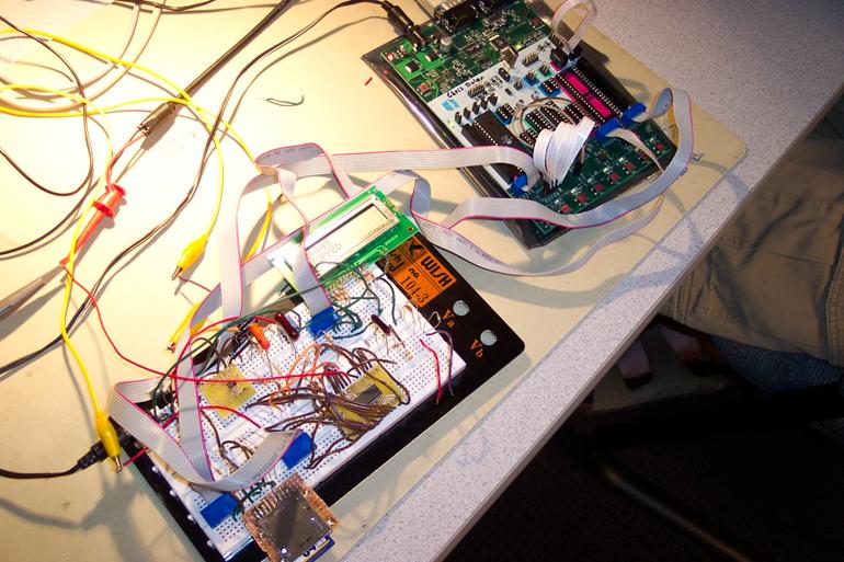
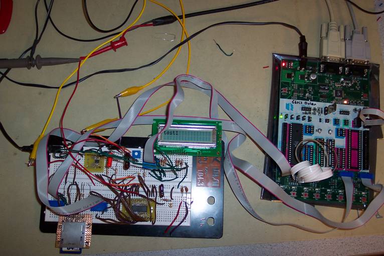
In this project we used an Atmel microcontroller, an LCD display, some pushbuttons, an mp3 decoder, and a digital to analog converter. We also used an SD (Secure Digital) card for storage to hold the MP3’s. An SD card can have MP3 files written to it using a PC. The card is formatted using the FAT file system that Microsoft Windows uses. The microcontroller is then used to read this SD card to get the mp3 data. Song titles are displayed on the LCD screen. Pushbuttons on the STK500 are used for functions such as skip to the next song, stop, and play. A mini-RCA jack (3.5mm audio jack) is used as the output of the mp3 player, which can be connected to a car-cassette adapter or a wireless FM transmitter (not included in the project). A 12V DC plug is the power source so that it can be plugged into the cigarette lighter of a car for power. The volume will be controlled by the car’s audio system. As the design only needs a 12V DC power source, no batteries are required. The mp3 player will never skip on bumpy surfaces as its just reading flash memory and there’s no disk drive or CD spinning that’s being read. Since the SD card is removable, the storage size can increase as new, larger SD cards are created, as opposed to being a fixed size like most mp3 players today.
High Level Design
Rationale:
The main reason for choosing an MP3 player as a project idea is that I’ve always wanted to build one. I’ve always been curious how it all works and I’m into digital circuitry in general, and I thought this would be a good culmination of a lot of things I’ve learned over the years. It involves C coding, building a complete circuit that involves digital and analog pieces, accessing external flash memory and a FAT file system, and the end result is something that you can actually use.
Background Math:
There weren’t really any calculations that needed to be done to begin the design. The most important calculation that could be done is to determine the maximum bit rate of the mp3 that we could support, for example, 128 kbps. There are two transfers for every bit of data: we must first get the mp3 data from the SD card, and then send it to the mp3 decoder. The fastest we can clock the transfer of data from the SD card is 4 MHz, and the fastest we can send a bit of data to the mp3 decoder is 8 MHz. But, these values don’t take into account all of the setup of the calls and the checking of loop variables that also need to be done. So therefore it really depends on how you implement the required functions. Also, our project was all done in C, which means it also depends on how the assembler translates our C code. You might have a function that you think only takes 1 cycle, but it could take more, and this would affect your calculation. Therefore we decided to just start testing with small bit rate files and determine the maximum bit rate later on. We did know, however, that it was possible to achieve some relatively decent bit rate (24 kbps or so) because others had done it with similar hardware and clock frequencies. Had we not had these other designs as references, we would have had to estimate our maximum bit rate based on what we thought the code would look like, but as you can imagine, this could be quite difficult and potentially not very accurate.
Logical Structure:
There were a few different stages to the creation of the design. First we needed to choose a microcontroller. We wanted to stick as close to the Atmel Mega32, as that’s what we were used to. But after researching other various designs, we found that a very popular choice for an mp3 decoder and DAC (digital to analog converter) were the STA013 and the CS4334. These two were proven to work well together, and there were at least a few other designs that had used these two. This gave us a lot of background information on how to use them, which made creating an mp3 player in a months time seem more feasible. But, the STA013 was a 3V chip and required 3V communication lines with the microcontroller. Since the Mega32 was a 5V chip, we would have needed to build level converter circuitry between these two chips. To avoid this, we used the Mega32L, which is very similar to the Mega32, but can be run at 3V. The downside to this is that it can only be clocked at a maximum of 8 MHz instead of 16 MHz. As the bottleneck of our design is currently the speed of the microcontroller, we realize we could have achieved higher bitrates by using the Mega32 and creating the level conversion circuitry, but the Mega32L did keep our hardware design simpler.
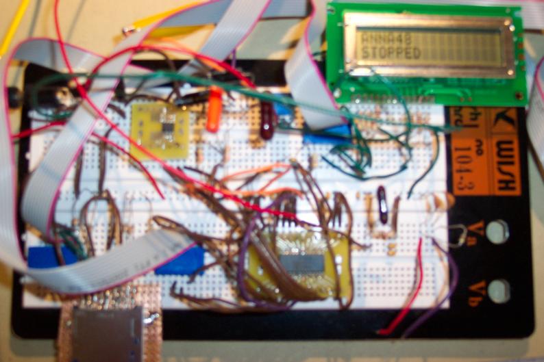
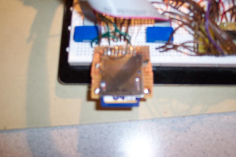
The next step was to choose what type of flash memory to use to store the mp3 files. We knew we wanted flash memory instead of a hard drive or cd-rom, as those are larger and require more energy to power them. We chose the SD card because it was one of the popular flash memory standards, it used the SPI interface so we only needed 4 I/O lines from our microcontroller, and it ran at 3V. The only other piece of hardware we needed was an LCD display. We chose a 16X2 LCD display that is very similar to the ones we had been using in lab all year. A schematic of the hardware is shown below (modified from http://instruct1.cit.cornell.edu/courses/ee476/FinalProjects/s2002/jmd48/nll4 jmd48 - EE 476 Final Project Web Page/476_final_project_schematic.htm and http://www.pjrc.com/mp3/sta013.html )
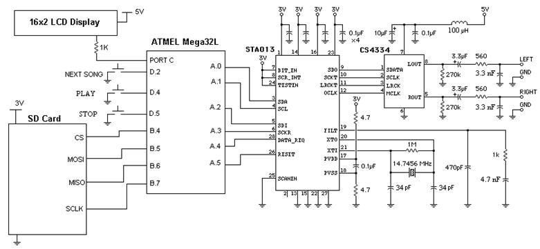
As I mentioned above, the majority of the schematic was used from http://www.pjrc.com/mp3/sta013.html. The SD card which used the SPI interface needed to be on port B as that’s what the SPI functions use. So the I2C code for the STA013 needed to be modified to used port A. Port C was connected to the LCD display, and port D was used for pushbuttons. D.0 and D.1 weren’t used, so that we could continually use HyperTerminal for debugging with printf’s. The CS4334 DAC didn’t require a connection to the microcontroller, as it was completely configured through the STA013. As shown in the schematic, there are 3 pushbuttons. Button 4 will play the song that is currently displayed on the LCD display. Button 5 will stop playing the current song. Button 2 will skip to the next song on the SD card and display its title on the LCD display. There is one last tricky part to point out here: the 1K ohm resistors running to the LCD display. The LCD display was a 5V display, while all the signals from the Mega32L were 3V. So we connected a 5V supply to Vdd on the LCD. But the LCD sends data signals back to the Mega32L, which we needed to limit to 3V. This is the job of the resistors. Also, the inputs of the Mega32L have protection diodes which will protect it from high voltages, so the resistors were all we needed.
Hardware/Software Tradeoffs:
- By choosing to use the Mega32L, it made the hardware simpler as we didn’t need any level conversion logic. But, this limited our maximum frequency to 8 MHz, which meant the code itself had to be faster and more efficient in order to achieve the same bit rate we could have with a 16 MHz clock on the Mega32.
- All of the code was written in C, but it could have run much faster on the hardware if we had written it all on assembly, as the compiler doesn’t always do the best job. But, due to our time constraints, programming everything in C was the only feasible option.
- The easiest way to program this code would have been to read an entire mp3 from flash memory and store it in RAM, then stream it from RAM to the mp3 decoder. But, we could only have a 512 byte RAM block to hold data, which meant we had to write code which would read 512 bytes from the SD card, then stream this data out, then read 512 more bytes, etc. This process works, but involves an overall slower data transfer rate from the microcontroller to the mp3 decoder.
Standards:
MP3, or MPEG-1 Audio Layer 3, is
digital audio encoding. It is a lossy compression format, meaning that if you compress the
data and then uncompress it, the new uncompressed version will not exactly
match the original version. According to
wikipedia.org, it uses psychoacoustic models to discard components less audible
to human hearing. This means that
frequencies and noises that people can’t hear anyway are removed, making the
amount of data that needs to be stored smaller.
There are various bit rates available: 32, 40, 48, 56, 64, 80, 96, 112, 128, 160, 192, 224, 256 and 320 kbit/s. There are also various sampling frequencies:
32, 44.1 and 48 KHz. 44.1
KHz and 128 or 192 kbits/s are said to be the
most popular right now. The mp3 file has
a standard format of which is a frame consisting of 384, 576, or 1152
samples. This value depends on the MPEG
version. Also, all the frames have
header information consisting of 32 bits and side information consisting of 9,
17, or 32 bytes which help the decoder to decode the encoded data
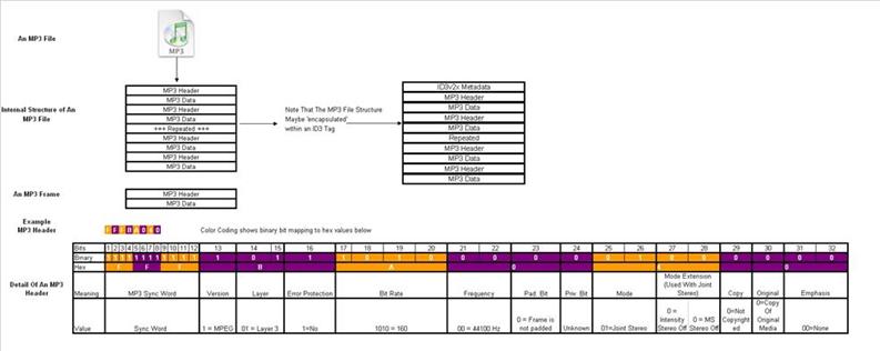
correctly. An mp3 frame consists of an
mp3 header and mp3 data. Multiple frames
create an mp3 file. The details for the
mp3 header are shown below, as taken from http://en.wikipedia.org/wiki/MP3.
Our mp3 decoder is smart enough that if it doesn’t see mp3 data, it doesn’t output anything to the DAC. It can also determine the correct bit rate and frequency of an mp3 by reading the header itself. Therefore, all you need to do is stream it the mp3 file, and it will do the rest for you.
Patents:
According to wikipedia.org, many different organizations have claimed ownership of patents related to decoding and/or encoding of mp3 files. There are open source encoders and decoders that patent holders allow to be distributed freely, but there has been legal action against certain companies selling mp3 devices without paying any licensing fees. Regardless, mp3 was patented in 1991, which means that by 2011, no patent could apply to mp3 any longer.
The SD card is also covered by patents, according to http://en.wikipedia.org/wiki/Secure_digital. Using the SD interface requires expensive royalties to be paid to the SDCA, but Wikipedia states that a common workaround for this is to use the MMC/SPI interface, which this project uses. While in this mode, you can not access the proprietary encryption features of the SD card, but this project only requires storing data, and encryption of the mp3’s would not really be useful anyway. MMC is an open standard that anyone can use, but the specification must be purchased from the MMC Association if it is needed.
Program
Details
We programmed the design in different pieces, and put it all together at the end. Step 1 was to access the SD card and be able to read and write data. Step 2 was to interface with the mp3 decoder, configure it, and stream some sample mp3 data to it. In step 3 we added code to support reading data from an SD card formatted with the FAT file system.
Step 1: The SD card
The information used to understand the SD card was taken from a few different sources: http://www.cs.ucr.edu/~amitra/sdcard/Additional/sdcard_appnote_foust.pdf, http://www.maxim-ic.com/appnotes.cfm/an_pk/3969, http://www.captain.at/electronic-atmega-mmc.php, and http://elm-chan.org/docs/mmc/mmc_e.html. The SD card interfaces with the microcontroller via SPI. We used some of information from http://instruct1.cit.cornell.edu/courses/ee476/SPI/index.html to understand an implement SPI. The base code that we began with came from http://www.captain.at/electronic-atmega-mmc.php. The description below refers to code in a file called mp3_withsd48test.c. This file is not part of the final project code, but was an important stepping stone on our way to the final result.
To start with, the code must include the spi.h file. This file allows us to use the Atmel SPI functions. We also make a note of which data lines are connected to which I/O pins: MOSI (master out slave in) is connected to B.5, MISO (master in slave out) is connected to B.6, SCLK (slave clock) is connected to B.7, and chip select is connected to B.4. In the initialize function we must set these I/O pins to the correct data direction. We must also correctly set the SPI configuration registers. This is shown below:
//set up SPI
//bit 7 SPIE=0 no ISR
//bit 6 SPE=1 enable spi
//bit 5 DORD=0 msb
first
//bit 4 MSTR=1 Mega32 is spi master
//bit 3 CPLO=1 clock polarity
//bit 2 CPHA=1 clock phase
//bit 1,0 rate sel=10 along with SPSR=1 sets clk
to f/32 = 250 kHz
SPCR = 0b01011110 ; //clock must not exceed 400 kHz for
initialization
SPSR = 1; //turn on SPI2x clock
//set up i/o data
direction for SPI
//connect MOSI B.5 to DI
//connect MISO B.6 to DO
//connect SCLK B.7 to CLK
//connect B.4 to chip select
DDRB.4 = 1; //output chip select
DDRB.5 = 1; //output MOSI
DDRB.6 = 0; //input MISO
DDRB.7 = 1; //output SCLK
It is important to set the SPI clock to be under 400 kHz for the initialization of SD card. After initialization is complete, we can increase the clock to 4 MHz, the maximum allowed when the MCU clock is 8 MHz (SPI clock max of f/2). After initialization we called the testSD() function. This function tests the SD card to make sure that it’s connected properly. First it calls MMC_Init(). MMC_Init follows an initialization flowchart from http://www.cs.ucr.edu/~amitra/sdcard/Additional/sdcard_appnote_foust.pdf:
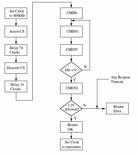
Our initialization differs slightly from this chart. For example, in the first step we set the clock to 250 KHz, not 400 KHz, due to the available SPI clock dividers and our 8 MHz base clock. The next step is to assert the CS line by setting PORTB.4 to 1. We then send 80 clock pulses, which just means writing 80 bits of data. This is done with the simple loop:
for(i=0; i < 10; i++) spi(0xFF); // send 10*8=80 clock pulses
By calling spi(0xFF), the microcontroller takes care of setting all the appropriate signals in order to send the 8 bits of data specified in the parameter. Since it’s a 1 bit serial line, each bit takes 1 clock pulse, so 80 bits of data will create 80 clock pulses. Next, the CS line is deasserted by setting PORTB.4 to 0. Sixteen more clock pulses are sent, similar to the code above except the loop is only performed twice. Now we can start sending commands. The first command is command 0, which is the reset command:
Command(0x40,0,0,0x95)
The Command function is pretty simple. Every command that goes to the SD card has 6 bytes. The format can be seen in this picture, from http://www.maxim-ic.com/appnotes.cfm/an_pk/3969:
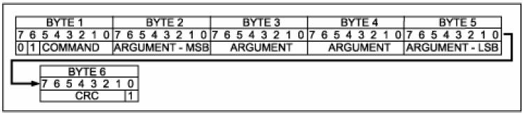
The first byte always starts out with a 0 then a 1 in the upper bits. Then the command you want to send is entered in the remain 6 bits of this first byte. For command 0, these bits are just 0. Then you pass arguments, depending on which command you send. If the command doesn’t take any arguments, or if it takes fewer that 4 bytes of arguments, then those bytes are just ignored. Lastly you send a 7 bit CRC, with a 1 in the least significant bit. The Command function takes 4 parameters: the command byte, two 16 bit arguments, and a CRC byte. The CRC byte is 0x95 or 0xFF for these commands, and for later commands the value of CRC is irrelevant. The Command function then just sends all of these values, bit by bit, to the SD card, as shown below:
char Command(char command, unsigned int AdrH, unsigned int AdrL, char CRCbits )
{ // sends a command to the MMC
spi(0xFF);
spi(command);
spi((unsigned char)(AdrH >>
8));
spi((unsigned char)AdrH);
spi((unsigned char)(AdrL >>
8));
spi((unsigned char)AdrL);
spi(CRCbits);
spi(0xFF);
return spi(0xFF); // return
the last received character
}
The return value of the function is the response from the SD card. There are different formats of the response, depending on the command issued. For all the commands we use, it responds in the R1 format, which is:
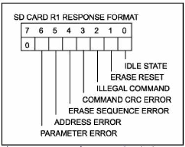
What we want to see is a return value of 1, which means the command completed and it’s in the idle state now. Now are ready to send command 41 and command 55, which are the initialization commands. These commands must be called until command 55 returns a 1 in the idle bit of the return value. Once this completes, the initialization is complete. If you want there are other checks that can be done, for example by issuing command 58 to read the operating conditions register, but it’s not necessary to do so.
Now that the SD card is initialized, we can speed up the SPI clock. The maximum speed you can run this clock at is the frequency of the clock of the microcontroller / 2, which is 4 MHz in our case. To set this up, you need to set the two SPI registers as follows:
SPCR
= 0b01011100;
SPSR
= 1; //turn on SPI2x clock
The default block size for a data transfer on an SD card should be 512 bytes. To guarantee this we can use command 16 to set the block length to 512, as follows:
Command(0x50,0,512,0xFF)
Now the SD card is properly configured. In order to test it, we need something to write to it. In this stage of our testing a function called fillram() is called, which simply writes a string over and over again into a block of ram (called sector[ ]) which is 512 bytes long. The function looks like this:
void fillram(void) { // fill RAM sector with ASCII characters
int
i,c;
c = 0;
for (i=0;i<=512;i++) {
sector[i] = mystring[c];
c++;
if (c >
17) { c = 0; }
}
}
The string used here (called mystring) is simply:
char *mystring = "Chris was here!
";
So now we have 512 bytes of RAM filled with multiple copies of this string. To write this data to the SD card, we call writeramtommc(). This function copies a string that is in RAM on the microcontroller to the SD card. The function looks like this:
int
writeramtommc(void) { // write RAM sector to MMC
int
i;
unsigned char c;
// 512 byte-write-mode (single block)
response = Command(0x58,0,512,0xFF);
if (response !=0)
{ //CMD24, which is a single block
write, addr is 512
printf("MMC: write error 1 \n\r");
printf("response = %d\n\r", response);
return 1;
}
printf("response = %d\n\r", response);
spi(0xFF);
spi(0xFF);
spi(0xFE); //start token
// write ram sectors to MMC
for (i=0;i<512;i++) {
spi(sector[i]);
}
// at
the end, send 2 dummy bytes (unused CRC bytes)
spi(0xFF);
spi(0xFF);
c = spi(0xFF);
printf("c1 = %d\n\r", c);
c &= 0x1F; // 0x1F = 0b.0001.1111;
printf("c2 = %d\n\r", c);
if (c != 0x05) {
// 0x05 = 0b.0000.0101
//if c=0x05, data is accepted
printf("MMC: write error 2 \n\r");
return 1;
}
// wait until MMC is not busy anymore
while(spi(0xFF) != (char)0xFF);
return 0;
}
First, command 24 is used to tell the SD card we are going to perform a write. This command has 1 argument: the address to which we would like to write to. In this case you can see that we are writing to address 512. The address has to be a multiple of 512, since the block size is 512 bytes. Once the command is accepted, we need to send the start token, which is 0xFE. Then we can write 512 bytes to the address we specified. So we call spi() for each byte of sector[] which transfers the desired 512 bytes to the SD card. We then send two dummy bytes at the end, and check to see what the response is. If the response is 0x05, then the data was accepted. Now we wait until the idle bit goes high by repeatedly sending 0xFF and looking at the idle bit. Once it goes high, we have completed the write, and we can return.
To really know if the write succeeded, we need to read from the SD card. To do this, we call sendmmc(). This function reads the data we just wrote to the SD card, and writes it to HyperTerminal. It looks like this:
int sendmmc(void) { //
send 512 bytes from the MMC
int
i;
// 512 byte-read-mode
response =
Command(0x51,0,512,0xFF);
if (response != 0)
{ //CMD17 is read single block, addr is 512
printf("MMC: read error 1 \n\r");
printf("response = %d\n\r", response);
}
// wait for 0xFE - start of any
transmission
startToken
= 0;
while(startToken == 0)
begin
response = spi(0xFF);
printf("response2
= %d\n\r", response);
if (response == 0xFE) startToken =
1;
end
for(i=0; i < 512; i++) {
recvd
= spi(0xFF);
// get character
printf("%c", recvd);
}
// at the end, send 2 dummy bytes
spi(0xFF); // actually this returns the CRC/checksum byte
spi(0xFF);
return 0;
}
Here we use command 17 to tell the SD card that we are going to perform a read, and we send 512 as a parameter to indicate the address we want to read from. Then we wait for the SD card to return the start token, which is 0xFE. To do this we keep sending 0xFF until we get 0xFE returned to us. At this point the read data is ready. To get it, we loop 512 times calling spi(0xFF) each time and print the return value which contains the data returned from the card to HyperTerminal. If the entire process is successful, we see “Chris was here! Chris was here! Chris was here!” printed over and over again on the screen.
Step 2: The mp3
decoder (STA013) and the DAC (CS4334):
To begin with, we define the mp3 decoder I/O names to the pins they correspond to:
// Define STA013 Pins
#define
I2C_SDA_direction DDRA.0
#define
I2C_SDA_in PINA.0
#define
I2C_SDA_out PORTA.0
#define
I2C_SCL PORTA.1
#define
DATA PORTA.2
#define
CLOCK PORTA.3
#define
DATA_REQ PINA.4
#define
RESET PORTA.5
As you can see, there are 4 outputs and 1 input. SDA and SCL are the data and clock pins used for the I2C connection. This is used for configuration purposes, such as to set up the mp3 decoder. DATA, CLOCK, DATA_REQ, and RESET are used to actually send mp3 data to the mp3 decoder. Note that there is an I2C library for the Atmel microcontrollers, but we didn’t use it here.
To configure the mp3 decoder, we call config_sta013(). This function is displayed below:
unsigned int config_sta013(void) begin
// Read from address 0x01 on the STA013
printf("Starting config_sta013\r\n");
address =
0x01; // Load the address into the address reg, r4
sta013_read(); //
Read data from the STA013
// Test if address 0x01 contains 0xAC
printf("data = %x, errorFlag =
%d\r\n", data, errorFlag);
if((data != 0xac)
|| (errorFlag != 0x00)) begin
printf("Error: STA013 Not Present, %d, \r\n", errorFlag); //
Print out the error flag
return 1; //
Return 1 to indicate that the STA013 is not present
end
else
printf("STA013 Present\r\n");
printf("beginning to load STA013 config
file\r\n");
// Send STA013_updatedata information to
STA013 (i.e., STA013 config file)
for (i = 0 ; i < max_config_index ;) begin
address =
STA013_UpdateData[i]; //
Load the address into the address reg, r4
data =
STA013_UpdateData[i+1]; // Load
the data into the data reg, r5
sta013_write(); // Write data to
STA013
// Increment i
i += 2;
// Check for an error in the write
if (errorFlag != 0x00) begin
printf("Error: STA013 Configuration Failed, %d\r\n", errorFlag); // Print
out the error flag
return 2; // Return 2
to indicate sta013 failed configuration
end
// Delay initialization for soft reboot
if (address ==
0x10) begin
delay_ms(1000);
end
end
printf("finished loading STA013 config
file\r\n");
printf("beginning to load STA013 board data\r\n");
// Send STA013 board specific data
for (i = 0; i < max_PLL_index;
) begin
address = config_PLL[i]; //
Load the address into the address reg, r4
data = config_PLL[i+1]; // Load the data into
the data reg, r5
sta013_write(); // Write data to STA013
// Increment i
i += 2;
if (errorFlag != 0x00) begin
printf("Error: STA013 PLL Configuration Failed, %d\r\n",
errorFlag); //
Print out the error flag
return 2; // Return 2
to indicate sta013 failed configuration
end
end
printf("finished loading STA013 board data\r\n");
printf("STA013 Configuration Complete\r\n");
return 0; //
Return 0 to indicate pass configuration
end
This function begins by making sure that the STA013 chip is present and wired properly. In order to do this, it performs a read from address 0x01 on the chip. This address contains 0xAC, so we need to make sure we can read this value from that address. To perform a read, the sta013_read() function is called:
void sta013_read(void) begin
printf("inside sta013_read\r\n");
// Start Condition
sta013_I2C_start();
//i2c_start();
printf("called I2C_start\r\n");
// Send the device address with the R/W bit
(i.e., the 8th bit) cleared
printf("about to try sta013_I2C_write\r\n");
I2C_byte = 0x86;
sta013_I2C_write();
if (errorFlag != 0) begin
printf("Read Error: Error writing device address (W) to
STA013.\r\n");
return;
end
printf("finished calling sta013_I2C_write, errorFlag = %d\r\n", errorFlag);
// Send the read address
printf("about to try sta013_I2C_write again\r\n");
I2C_byte = address;
sta013_I2C_write();
if (errorFlag != 0) begin
printf("Read Error: Error writing read address to
STA013.\r\n");
return;
end
printf("finished calling sta013_I2C_write again, errorFlag = %d\r\n", errorFlag);
// Start Condition
sta013_I2C_start();
printf("called I2C_start again\r\n");
// Send the device address with the R/W bit
(i.e., the 8th bit) set
printf("about to try sta013_I2C_write 3rd time\r\n");
I2C_byte = 0x87;
sta013_I2C_write();
if (errorFlag != 0) begin
printf("Read Error: Error writing device address (R) to
STA013.\r\n");
return;
end
printf("finished calling sta013_I2C_write 3rd time, errorFlag = %d\r\n", errorFlag);
// Read the data from the given address
printf("about to try sta013_I2C_read\r\n");
sta013_I2C_read();
printf("finished calling sta013_I2C_read, data =
%x\r\n", data);
// Stop Condition
sta013_I2C_stop();
end
To do any sort of I2C command, you first need to call the sta013_I2C_start() function:
void sta013_I2C_start(void) begin
// High to low transition of I2C_SDA while
I2C_SCL is high
I2C_SDA_direction = 1;
delay_us(5);
I2C_SDA_out = 1;
delay_us(5);
I2C_SCL = 1;
delay_us(5);
I2C_SDA_out = 0;
delay_us(5);
I2C_SCL = 0;
delay_us(5);
end
This function prepares the chip for a command. First we set the direction to 1 to make it an output. Data is sampled on the rising edge of the clock, so we first set the SDA line to 1 and then bring the clock line high. Next we set the SDA line to 0 and drop the clock line. This signifies a start condition. There are 5 microsecond delays in between all of the I2C changes. This is because I2C can’t be clocked very fast, and since this is just a 1 time configuration anyway, we chose a high delay between all I2C transactions to ensure correct operation.
Now that the start condition is done, we send the value 0x86 to signify that we would like to perform a read. We store 0x86 in I2C_byte, and call sta013_I2C_write():
void sta013_I2C_write(void) begin
// Clock each bit onto the SDA bus (starting
with the MSB)
I2C_SDA_direction = 1;
for(j = 7; j >=
0; j--) begin
delay_us(5);
I2C_SCL = 0; //I2C_SCL is the clock (what
is the min/max clock speed?)
delay_us(5);
I2C_SDA_out = (I2C_byte >> j) &
0x01; // Write each bit while I2C_SCL is
low
delay_us(5);
I2C_SCL = 1;
delay_us(5);
end
// Get the ack bit
I2C_SCL = 0;
delay_us(5);
I2C_SDA_direction = 0;
delay_us(5);
I2C_SCL = 1;
delay_us(5);
errorFlag
= I2C_SDA_in; //should be a 0
delay_us(5);
I2C_SCL = 0;
end
To write data over the I2C bus, you set the SDA direction to output, lower the clock, write the data bit, and raise the clock. You repeat this lowering of the clock, sending a bit, and raising the clock until you have sent your data byte. To receive the ack bit, you set the SDA direction to input, lower and raise the clock, and then read SDA. The value should be a 0 if everything went ok. Finally, lower the clock again and exit the function.
Now we need to perform another write to send the address that we want to read from. The void sta013_I2C_write() function is called again, except this time the address to read from is stored in the I2C_byte variable. Now the STA013 knows which address we want to read from, and we just need tell it that we’re going to do a read next. To do that, we do another write with value 0x87, saying we’re ready to read. Once this is complete, we can call sta013_I2C_read():
void sta013_I2C_read(void) begin
data = 0x00;
// Clock each bit off of the SDA bus
I2C_SDA_direction = 0;
delay_us(5);
I2C_SCL = 0;
delay_us(5);
for(j = 7; j >=
0; j--) begin
I2C_SCL = 1;
delay_us(5);
data = data |
(I2C_SDA_in << j); // Read the
bit while I2C_SCL is high
delay_us(5);
I2C_SCL = 0;
delay_us(5);
end
end
This function just reads bit by bit while controlling the clock. The data changes on a low to high transition, so after the clock is high a new data bit can be read. We now have the data at address 0x01, and we just need to check to make sure it’s 0xAC. If it is we can move on. We also need to call the sta013_I2C_stop() function, which tells the STA013 that we are done with it for now:
void sta013_I2C_stop(void) begin
// Low to high transition of I2C_SDA while I2C_SCL
is high
I2C_SDA_direction = 1;
delay_us(5);
I2C_SDA_out = 0;
delay_us(5);
I2C_SCL = 1;
delay_us(5);
I2C_SDA_out = 1;
delay_us(5);
I2C_SCL = 0;
delay_us(5);
end
This function simply changes the SDA line from low to high which the clock line is high, which is the stop condition for the STA013.
The next
step is very important. The STA013
requires some configuration data in order to function properly. This data is available in a file from
STMicroelectronics, here: http://www.st.com/stonline/products/families/audio/audiodecoders/mp3/sta013.htm. The file is called p02_0609.bin, and contains many pairs of addresses and data
that need to be written to the STA013.
This data is stored in an array called STA013_UpdateData. These address/data pairs are loaded into the
address and data variables, and sta013_write() is
called:
void sta013_write(void) begin
// Start Condition
sta013_I2C_start();
// Send the device
address with the R/W bit (i.e., the 8th bit) cleared
I2C_byte = 0x86;
sta013_I2C_write();
if
(errorFlag != 0) begin
printf("Write Error:
Error writing device address (W) to STA013.\r\n");
return;
end
// Send the write address
I2C_byte = address;
sta013_I2C_write();
if
(errorFlag != 0) begin
printf("Write Error:
Error writing write address to STA013.\r\n");
return;
end
// Send the data
I2C_byte = data;
sta013_I2C_write();
if
(errorFlag != 0) begin
printf("Write Error:
Error writing data to STA013.\r\n");
return;
end
// Stop Condition
sta013_I2C_stop();
end
This function is in some ways similar to the sta013_read() function. First you need the start condition, then you need to write 0x86, and finally you write the address and then the data. You also need to keep checking the ack bit to make sure it is a 0. Lastly you write the stop condition, and you are done. This address/data writing must be done for all pairs of address and data in the configuration file. Once we write to address 0x10, we need to delay for a while to allow for a reboot of the chip. A delay of 1 second (1000 ms) worked just fine for this. After all this data is written, we need to write data to tell the STA013 how to talk to the DAC. Following the STA013 data sheet, we use the address/data pairs stored in config_PLL. All of these values need to be written to the chip just as with the previous configuration data. Once all of this data has been written, the configuration of the STA013 is complete.
The next step is to call the sta013_start() function:
void sta013_start(void) begin
printf("Inside sta013_start\r\n");
// Write 1(0x01) to address 114(0x72)
address = 0x72;
data = 0x01;
sta013_write();
// Check for an error
if (errorFlag != 0x00)
printf("Error: STA013 Start Failed, %d\r\n", errorFlag);
else
printf("Starting mp3 player...\r\n");
end
To tell the chip to start accepting data to fill its internal 256 byte buffer, we need to write a 1 to address 0x72. If this is successful, the STA013 will raise its DATA_REQ (data request) line, and we can start sending data until the buffer is full and the DATA_REQ line drops back down. As this code is just a test, we set the start_flag to 1 so that sta013_play() would also be called:
void sta013_play(void) begin
printf("Inside sta013_play\r\n");
// Write 1(0x01) to address 19(0x13)
address = 0x13;
data = 0x01;
sta013_write();
// Check for an error
if (errorFlag != 0x00)
printf("Error: STA013 Play Failed, %d\r\n", errorFlag);
else
printf("Playing MP3...\r\n");
// Write 0(0x00) to address 20(0x14)
address = 0x14;
data = 0x00;
sta013_write();
// Check for an error
if (errorFlag != 0x00)
printf("Error: STA013 Unmute
Failed, %d\r\n", errorFlag);
else
printf("Unmute
succeeded\r\n");
end
To tell the STA013 to start reading data from its buffer and sending signals the DAC, we need to write a 1 to address 0x13. We also added code to write a 0 to address 0x14, which disables the mute. This might not be necessary, but it’s safer to just clear the bit anyway. All that is left to do now is to start sending data. As long as the DATA_REQ line is high we can send more data. To send data, we call the STA013_mp3_data_chris() function:
void STA013_mp3_data_chris(void) //max value is 21428
begin
mp3_byte = mp3_data[mp3_pointer];
mp3_pointer = mp3_pointer + 1;
if (mp3_pointer >
21428) mp3_pointer = 0;
for (j = 7; j
>=0; j--)
begin
CLOCK = 0;
DATA = (mp3_byte >> j) & 0x01;
CLOCK = 1;
end
end
This is a simple function: it just grabs data from the RAM on the microcontroller 8 bits at a time, lowers the clock line, puts 1 bit out, raises the clock line, and repeats this a total of 8 times. Therefore, calling this function sends 1 byte of data to the mp3 decoder. The decoder can always accept 1 byte of data if DATA_REQ is high, so sending 8 bits at a time is safe. For this test, we use some mp3 data in an array called mp3_data. This data is from a 48 kbps file. To create this data, we used two Perl scripts. One Perl script reads the data directly from an mp3 file and converts it, but not to the proper format for adding into a CodeVision C file. We wrote another Perl script that converts the output from the first script into the proper format. These two files can be found here: convert.pl, mp3_to_hex.pl. Flash memory can’t hold an entire mp3 file, so we just added as much as we could until flash was full. In the end we were able to store about 3 seconds of an mp3 file which we looped over repeatedly for testing purposes.
Step 3: Including FAT
compatibility and putting it all together:
By completing the above two steps we confirmed that we had appropriately wired the SD card and mp3 decoder and that we understood the basic configuration of both devices. The next and final step was to be able to stream data from an SD card that was formatted with the standard Windows FAT file system and send this data to the mp3 decoder.
While doing research on the organization of the FAT file system we came across a library that provided FAT support for a variety of microcontroller families. The original source code and associated documentation for the library can be found at http://elm-chan.org/fsw/ff/00index_e.html. The site provides two different versions of the code, one that supports multiple attached drives (FatFs) and one that allows only a single drive intended for devices with limited memory (Tiny FatFs), as well as examples of how to use the code with a number of different MCUs, including an example for the Mega64. The code provides support for a number of different storage interfaces including ATA, Compact Flash, and MMC as well as an interface to add your own storage device if desired.
For this project we used the Tiny-FatFs and MMC code provided by the library. We chose the Tiny-FatFs version due to its smaller code profile and were able to used it almost verbatim with little if no change. The setup and use of the provided FAT library functions with be discussed later. The MMC code that interfaced with the FAT code required a little more modification to migrate it to a Mega32 and the CodeVision SPI library. Within the MMC code we needed to change some of the module private functions which handled the physical interface between the MMC/SD card and the MCU. Specifically we changed xmit_spi(dat), rcvr_spi (), rcvr_spi_m(dst), power_on(), power_off(), and disk_timerproc(). The xmit_spi and rcvr_spi functions, as their names imply, are used to send and receive SPI data respectively. Since SPI really always transmits and receives data each time these functions also either received or sent garbage data depending on the function (this garbage data was simply discarded). To provide the best possible performance both of these functions used the assembly equivalent C SPI commands discussed in http://instruct1.cit.cornell.edu/courses/ee476/SPI/index.html instead of calling the spi() library function itself. For example, the rcvr_spi was implemented as
static BYTE rcvr_spi
(void){
SPDR=0xFF;
while ((SPSR.7)==0);
return SPDR;
}
instead of just spi(0xFF). The receive function also had a macro version defined as
#define rcvr_spi_m(dst) SPDR=0xFF; while(SPSR.7==0); *(dst)=SPDR;
which was used in performance critical area such as when streaming a large block of data to or from the SD card where the overhead of repeated function calls could degrade performance notably.
The power_on() function in the original code was used to turn on the SD card interface and appropriately setup the SPI port and control registers. Since the code was intended for a Mega64 we had to update this function to set the port B data direction register as well as the associated SPI control registers for a Mega32 instead. The exact code used to initialize the SPI registers was
static void power_on
(void){
for (Timer1 = 3;
Timer1; ); /* Wait for 30ms */
PORTB = 0b10110101; /* Enable drivers */
DDRB = 0b10110011;
SPCR = 0b01011110;
SPSR = 0b00000001;
}
The power_off() in the original code was set to power off the SD card. Since we did not desire this functionality we simply commented the code in this function but left the function in place incase there was some later desire to implement this functionality. The disk_timerproc() is required for write support. If write support is enabled the function should be called every 10 ms to update some internal counters. Since we only required read support on the MP3 player side we did not need most of the functionality provided by this function. In our initial tests, however, we were calling this function and it was causing some problems in the way it changed the MMC stat value. Specifically this function was checking SD lines to see if a card was available and if the card was write protected. Since we did not connect these lines in our design (we connect just the 4 lines needed for SPI) the status register was being set saying that no disk was present even when a disk was in the reader. To remove this problem we simply commented out these checks and set the status register ourselves to the correct value.
The final change we had to make to the mmc code work was to update the #defines for the SELECT() and DESELECT() commands. These commands set the chip select line either low or high. We initially missed this change and the card would not initialize properly. Once we update the #defines to set the appropriate port B pin, PORTB.4, the entire initialization worked without a problem. In the process of debugging this problem we did a detailed comparison of our initial SD initialization routine described above and the disk_initialize() routine provided in mmc.c. We found that, although the disk_initialize() version included a number of additional options, the case that was getting executed for our setup performed the same set of operations as our original initialization routine. This gave us further confidence in both our code and the code provided in this library. As one final addition, at the end of disk_initialize() we add the lines
SPCR = 0b01011100;
SPSR = 1;
to change the SPI clock speed from the initialization speed of 250 kHz to the full fosc/2 (4 MHz)
Once the mmc.c code was correctly updated the rest of the Tiny FatFs code worked with very little modification. The only change we made to the rest of the code in the library was in tff.h where we changed the #define _FS_READONLY to 1 instead of 0 as we only needed read functionality. This removed any of the write related functions from compilation and saved on compiled code size.
To integrate the FAT code into our main file we included tff.h, mmc.c, and diskio.h in main. We also added tff.c and mmc.c to the project within CodeVision. To initialize the file system we first call disk_initialize(0) to initialize the SD card followed by f_mount(0, &fatfs) to make the program aware of the file system on the card. Both of these functions should return 0 if they complete successfully. After initialization any of the standard file IO calls provided by the FatFs code can be used. For our MP3 player we used f_read, f_readdir, f_open, f_close, and f_opendir. We use f_opendir and f_readdir to get a list of all of the files in the root directory and f_open, f_read, and f_close to handle reading mp3 data to be played.
To get a list of files on the card we first call f_opendir(&dir, filename) where filename contains the empty string “”. This will place the opened directory in dir. To get the name of the first file in the directory we call f_readdir(&dir, &finfo). This function places info on the function, which includes its name, in finfo. To get the next file in the directory we simply call f_readdir again. We continue to call f_readdir so long as it returns FR_OK and the name of the file is not null. Once we reach the end of the directory we reopen the directory so we can begin displaying files from the beginning of the directory again.
When the user presses the play button indicating that they wish to listen to the displayed song, we first open the file using f_open(&file1, filename, FA_READ). This function specifies that we wish to open the file with the name stored in filename, we wish to open the file as read only, and a pointer to the file should be placed in file1. Once the file is open we begin calling f_read(&file1, Buff, 512, &s2) to read 512 byte chunks of the file. The function reads up to 512 bytes of data from file1 and places the read data in Buff (which is an array of chars). The function returns the actual number of bytes read in s2. We continue reading data and sending it to the mp3 decoder until s2 becomes 0 indicating that we have reached the end of the file. At this point we call f_close(&file1) to close the file. We then get the next file in the directory, open it, and start reading blocks to begin playing the next song.
Hardware Details
By following the schematic above, everything worked fine. The only other pieces we needed was a 5V regulator to power the LCD display and the DAC at the correct voltage level, a12V cigarette lighter adapter for a car so that the player can be powered off of a car battery, and a headphone jack so that speakers or some other device can be plugged into the output of the DAC. There is one important note. The DAC, although running at 5V, can receive 3V inputs STA013 with no problems. A logic high from the STA013 is still seen as a logic high to the CS4334. Also, it was important to make sure the grounds for both the 5V power supply and the 3V power supply were connected so they were at the same level. The circuit would not function properly otherwise.
Results
When we finished the project, we could successfully play mp3’s off of the SD card. When the system was turned on, we could scroll through the available mp3 files on the SD card, choose one, and play it without problem. Once one song finished playing the next would start and the playback could be stopped at anytime.
Speed of Execution:
This was a pretty important aspect of the project, as it affected the maximum bit rate that we could play. The maximum bit rate achieved was 64 kbps. This was determined through listening to a series of songs with increasing bitrates while listening for skips, as well as scoping the DATA_REQ and CLOCK signals. The CLOCK signal was important because it would tell us when we were sending data. If we weren’t sending data, either due to DATA_REQ being low, or if we were reading data from the SD card, then the mp3 decoder clock would stop. Otherwise, it would be oscillating indicating we were transferring data. So, if we also look at the DATA_REQ signal, we can see why the clock is stopped. The clock doesn’t always have to be moving, because the input buffer in the STA013 might be full, and therefore you can’t send anymore data. The problem occurs when DATA_REQ is high, but the clock stops anyway because you’re reading mp3 data from the SD card into RAM. If this takes too long and all of the mp3 data in the STA013 is used up, then there is a pause in the song while new data is fetched, which manifests as skips in the music. To further illustrate the idea refer to the following picture:
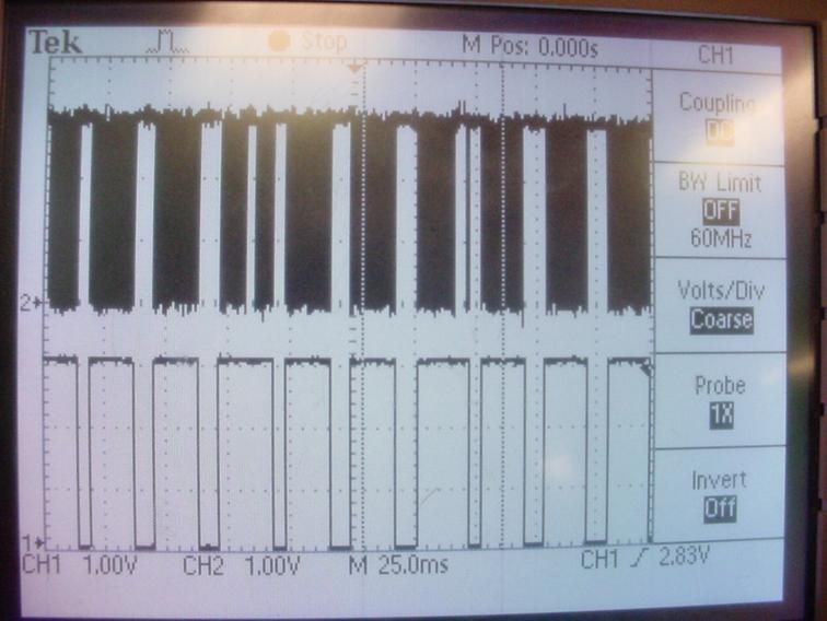
Here you can see the CLOCK signal on the top, and the DATA_REQ signal on the bottom. Most of the time when the clock stops, it’s because DATA_REQ is low, which is fine. That means we’ve filled the buffer and are satisfying the data transfer rate requirements. Occasionally you can see the clock stops even when the DATA_REQ line is high, which indicates we are reading 512 bytes of data from the SD card. This transfer is fast, however, because it’s being clocked at 4 MHz. So it is a relatively quick pause, and the internal buffer of the STA013 has plenty of data to keep decoding through this process up to a certain bitrate. This is a scope image of a 48 kbps song. If the mp3 data rate is too high, the STA013 consumes the data in its internal buffer much faster, which means reads from the SD card are more frequent, and at some point you can’t read a full block of data before the STA013 empties its buffer at which point you start hearing short pauses in the song.
Accuracy:
Perfect accuracy is hard to judge, as looking at the output of the DAC varies dramatically. The best way to judge the accuracy of the mp3 player is to simply listen to it compared to a computer or other mp3 playing device. To us the songs sound perfect, and so we believe that it is accurate enough. If there is any inaccuracy, it’s not enough for a human to detect.
Safety and Interference:
This project didn’t have any safety concerns. It was low voltage and therefore there wasn’t any way to get shocked. There were also no moving parts or other dangerous pieces to it. It also didn’t create any kind of wireless communication, so there shouldn’t be any interference problems.
Usability:
Our design is pretty easy to use. You can just put mp3’s on the SD card with an SD card reader attached to your computer, as long as they are below the maximum bit rate. Converting mp3’s to various bitrates is achievable through many different software programs. I used a program call MusicMatch Jukebox (http://www.musicmatch.com/) that I had on my computer, but others have used the LAME mp3 encoder: http://www.mp3dev.org/. Once you have transferred your music, you simply put the SD card into the card reader of the mp3 player, turn it on, and after it boots up you can scroll through the songs on the SD card. Once you find one you like, you can hit play and it will start playing. At any time, you can scroll to a different song, or stop the playback.
Conclusions
Our project met the specification we created for it in the project proposal. It can read an SD card, read the FAT file system, and stream mp3 data to a decoder and then a DAC. There are ways the design could be improved. We could have added more buttons for more functionality. For example, the STA013 has registers you can write to for volume control. We could have also achieved higher bitrates by better optimizing some of the code. Writing frequently used parts of the code in assembly would also have sped up the operation of the design and allowed us to play songs with higher bitrates. If we had more time, we could have added these features.
This design conformed to the SD and mp3 standards. If it didn’t, then it wouldn’t have worked. We did however use others code as described above. Therefore we probably couldn’t patent this mp3 player and start selling it. Although, the reason we used others code was to understand what we needed to do. At this point we understand it well enough that we could completely write all of the required code without using any of other people’s code. But as the design wouldn’t be competitive with other mp3 players out there anyway, there doesn’t seem to be any desire to try to build and sell this design.
Ethical Considerations
Here we comment on how our on work on this project followed the IEEE Code of Ethics:
1.
To accept responsibility in making engineering decisions consistent with
the safety, health and welfare of the public, and to disclose promptly factors
that might endanger the public or the environment
As there are no sharp or moving parts, and all circuitry is low voltage, there is no danger to the public when using our mp3 player.
2. To avoid real or
perceived conflicts of interest whenever possible, and to disclose them to
affected parties when they do exist
Our design
wasn’t meant to compete with any other mp3 players out there, so conflicts of
interest shouldn’t be a problem
3.
To be honest and realistic in stating claims or estimates based on
available data
All of the data and information written in this report is true to the best of our knowledge. Any estimates we made were our best guess, and further experimentation would be necessary to state them as facts.
4. To reject bribery
in all its forms
No one tried to bribe us, although I can’t imagine why anyone would J
5.
To improve the
understanding of technology, its appropriate application, and potential
consequences
The main reason of choosing this project was to try to further our understanding of technology and how the involved components worked. Through the problems we found and solutions we discovered we learned a lot.
6.
To maintain and improve our technical
competence and to undertake technological tasks for others only if qualified by
training or experience, or after full disclosure of pertinent limitations
We knew going into this project
there was a lot we didn’t know about it, but with the help of
7.
To seek, accept, and offer honest criticism of technical work, to
acknowledge and correct errors, and to credit properly the contributions of
others
We acknowledge that our code isn’t optimized as much as it could be, and it could be improved. What we did was the best we could with the time we had. We also pointed out the various instances where we used someone else’s code or designs to lead us to our final design.
Appendix A: Commented Code
The files we used in our code, and the other file that I used to explain some of our functions (mp3_withsd48test.c) are linked below:
Appendix B: Overall Schematic
The following is a schematic of our design:

Appendix C: Parts List
|
Part |
Cost |
|
Atmel ATMega32L |
$8.17 (digikey) |
|
8MHz oscillator |
$0 – I own one |
|
STK500 |
$0 – I own one |
|
Singapore Technologies STA013 (MP3 decoder) (3V) |
$10.83 (digikey) |
|
14.7456 MHz oscillator (for STA013) |
5 for $1.00 (AllElectronics) |
|
Cirrus Logic - CS4334 D/A Converter (5V) |
$2.57 (digikey) |
|
DIP adapters -Aries Electronics 32-pin adapter (STA013) -Aries Electronics 8-pin adapter (CS4334) |
$0 – Built both in lab |
|
16X2 LCD display |
$6.00 (AllElectronics) |
|
3 pushbuttons |
On STK500 |
|
12V cigarette lighter adapter |
$0 – previously owned (from broken 12V spotlight) |
|
5V voltage regulator (for CS4334) |
$0.48 http://www.eidusa.com/Electronics_Voltage_Regulator.htm |
|
SD card |
$0 – previously owned |
|
SD card adapter (to attach to breadboard) |
$3.74 (Digikey 478-2016-1-ND) |
|
Breadboard |
$0 – previously owned |
|
Total |
$32.79 |
Appendix
D: Tasks
Most parts of the project were done by both members of the group. The following are the specific tasks involved:
- Understanding and writing code for the SD card: Chris
- Understanding and writing code for the STA013 and CS4334: Chris
- Using this code and other code to add FAT file system compatibility to the final design: Matt
- Writing Perl scripts for creating mp3 test data: Chris
- Testing the Code: Chris and Matt
- Ordering and buying parts for the project: Chris
- Designing the Hardware: Chris
- Testing the Hardware: Chris
- Soldering the Parts: Chris
- Integration and final testing: Chris and Matt
- Writing the Report: Chris and Matt
- Creating the webpage: Chris
Appendix
E: References
http://www.pjrc.com/mp3/sta013.html
http://en.wikipedia.org/wiki/MP3
http://en.wikipedia.org/wiki/Secure_digital
http://www.cs.ucr.edu/~amitra/sdcard/Additional/sdcard_appnote_foust.pdf
http://www.maxim-ic.com/appnotes.cfm/an_pk/3969
http://www.captain.at/electronic-atmega-mmc.php
http://elm-chan.org/docs/mmc/mmc_e.html
http://instruct1.cit.cornell.edu/courses/ee476/SPI/index.html
http://www.captain.at/electronic-atmega-mmc.php
http://www.st.com/stonline/products/families/audio/audiodecoders/mp3/sta013.htm
http://elm-chan.org/fsw/ff/00index_e.html
Pictures