Touch Screen Controlled R/C Car
Tytus Mak
Daniel DiBernardo
Introduction
For our final design project, we chose to build a touch screen radio controlled car. Essentially, the RC car will follow a path drawn by the user on the touch screen as it is drawn in real time. Speed and direction of the car was extrapolated from the user drawn path and sent to the car through radio frequency transmission. We utilized a touch screen taken from an old Palm Pilot, the chassis of an old RC car (including the motors), and a transmitter receiver pair. All circuits for both the controller unit and the car were custom built.
We chose this particular project because RC cars are just plain fun, and thus we chose to create something that is essentially a new twist to an old idea. Numerous projects on RC cars have been done throughout the years, but we felt that none of the control schemes were ever intuitive enough to use to absolute beginners. Nothing can be more intuitive than controlling an RC car by drawing the path that you want it to take.
Project overview
The main rationale behind this project was that it seemed to be a fun and interesting idea to implement. Sources of inspiration initially came from previous projects, specifically the numerous RC car projects over the years, as well as the handwriting recognition project from 2006. The handwriting project utilized a touch screen, which gave us the idea to apply the user input tracking capability of the touch screen to an RC car control scheme. However, whereas the handwriting recognition project utilized the touch screen for recognizing drawn patterns, our project would require a greater deal of precision and timing from the screen. We also realized that a user drawn path was a very analog input that would require that the RC car itself have a large number of different turn angles and speeds. The challenge was in writing the algorithm that would effectively extrapolate both speed and direction of the car from the user drawn path in real time, and creating a car that would be capable of following this path.
Background Math
The math involved in extrapolating speed and direction to control the car is essentially nothing more than basic high school geometry. The user input path is quantized into numerous points, which are taken 30 times every second. Below is an example of a user input path:
The touchpad is quantized into a 190 x 140 grid of points (based entirely on the real life dimensions of the screen itself) and the microcontroller will grab the coordinates of the current location of the user stylus (or nailed finger) 30 times a second. If the user speeds up the stylus, naturally the points will be further spaced apart. It is entirely from this quantization that both speed and direction are calculated.
Speed –
Extrapolating speed is a simple matter of calculating the length between each successive point. The longer the distance between successive points, the faster the car should be going. Calculating this distance is a trivial matter of utilizing Pythagorean’s Theorem: However, as one can plainly see the points are very close together most of the time, rarely exceeding the distance of 1 to 2 pixels from each other, as can be seen in the graph below.
This means that the calculated distances are, for the better part of the time, either 0, 1, or 2. This makes extrapolating the speed a little more difficult, and a lot less analog than we would like it to be. Thus we solve this problem by simply averaging the previous 2 distances with the current distance. This gives a much more varied speed calculation, as can be seen from the following plot:
Direction –
Extrapolating the direction from the points requires a bit more math and a lot more creativity. What is most important here are the not the absolute angles derived from the points, but the angle compensation needed by the car with respect to its current position in order to correctly follow the user path. The desired final output is the angle that the car’s wheels must turn in order to keep following the path. Of course a car is restricted in the range of angles it can turn, thus all angles greater than a predefined value are declared as invalid inputs.
Once again we have the problem of the points being too close together to extrapolate any real useful data, thus for direction calculations, every group of 15 points are averaged, and the direction calculated from these points. This means that, assuming a sampling frequency of 30 points/second, the direction will only be updated twice a second.
The basic math behind deriving absolute angles between points is simple trigonometry. What we desire in the end is the change in the angle from the previous value, illustrated below:
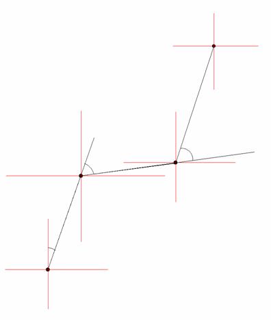
The lines that connect each point have been elongated to illustrate the placement of the desired angle. This angle can be easily calculated by first calculating the absolute angle from the line connecting the current point and the previous point with respect to the Y-axis.
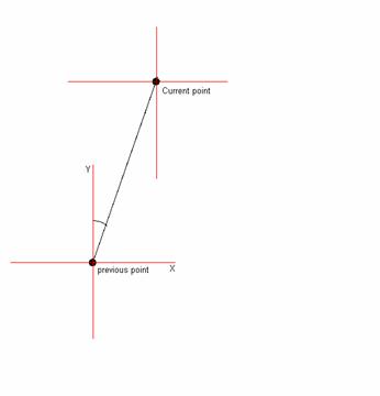
Then the previous calculated absolute angle formed by the previous formed line from the past point must be subtracted from this current angle. This final angle will effectively be the angle that the wheels of the car must turn to follow the user defined path.
Embedded within the problem of finding the turn angle lays the problem of detecting when the car needs to move backwards: Below is an example of a user input that would result in the car moving forward, then moving backwards, and then moving forwards again.
The problem at hand is detecting when the change in direction is sharp enough to change the motion of the car from forwards to backwards. It is this acute angle, that any person can obviously see, that must be reliably and efficiently detected through code. Again, we will be exploiting the simple properties of high school geometry to accomplish this task. The Law of Sines dictates that for triangles, an angle is proportional to the length of the side directly opposite to it. Thus this acute angle that is indicative of a change in the movement direction of the car can be quickly extrapolated through the length of sides formed by three points. Below is an illustration of this theory:
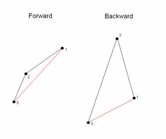
The most recent detected point is labeled point 1, and each previous angle is designated as points 2 and 3. As one can plainly see, when moving forward, the length of the line formed between points 1 and 3 will always, without exception exceed the length of both the lines formed between points 1 and 2, and 2 and 3. When moving backwards, the line formed by 1 and 3 will always be shorter than at least one of the other two lines.
Logical Structure
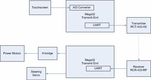
The high level structure of our project is succinctly illustrated in the diagram below:
Hardware/software Tradeoffs
We realized from the beginning that following a user input path has numerous pitfalls. The most obvious problem lies in the fact that a user input path cannot be exactly translated to RC car movements. The RC car has a very limited range of angles it can turn, and a user input path can very easily exceed the rate of turn for the car. Furthermore, the user can easily move the stylus faster than the car can reasonably follow. Thus, fail safes were programmed into the code that would reject movements that were too fast, or angles too large for the car to follow.
FCC Standards
Our transmitter complies with FCC standards since it does not interfere with licensed transmitters and it transmits in the acceptable range of frequencies found in Part 15 of the FCC rules (http://www.access.gpo.gov/nara/cfr/waisidx_01/47cfr15_01.html). The circuits that we used save power by inverting the transmitted bit stream so that it transmits a 0 when no signal is being transmitted. We do not plan on selling any of our products and we are building less than five of them, so no equipment authorization is required.
Software Design
The software required for this project consisted of two primary code bases: the code on the user side control hardware, and the code needed to properly operate the car. All mathematical calculations for generating speed and direction was performed on the ATMEGA32 controller on the user end, and the controller on the car simply took in wheel angle position and speed through RF, and generated the correct signals for operation.
Touch screen point
capturing
Timing was an essential factor in correctly capturing the coordinates for the current stylus position. A new point was taken in every 33.3 milliseconds (30 points/sec), which was assured by regulating this through interrupts. As described above, the touch screen can only output either the X or Y coordinate at any one time, thus input and output must be quickly swapped between the four pins to get both values. The setup that was used in the Handwriting Recognition System project, which required changing pins from input to output, and output to input depending on which coordinate was being read, was used in our code as well, but with heavy modifications. Timing was less of an issue for their project, which relied on recognizing the pattern drawn rather than the absolute positions. However, for our project, we needed to be able to grab these points as quickly as possible. Below is the state machine used to correctly read in the coordinates:
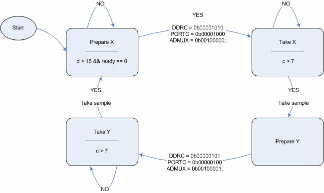
There is a need for a 7 millisecond wait time from switching the port pins to actually reading in the value from the ADC because of the low pass filter. During this time interval the voltage reaches its proper peak value, which can then be properly read in.
Speed and direction
calculations
Within the 33.3 millisecond timeframe between successive points, it was necessary to perform all needed calculations for both speed and direction. The math that was involved required very costly operations such as squaring, square roots, and arctangent calculations. The timeframe between each point only allows for approximately 532,800 instructions to be executed, thus shortcuts were taken to minimize the cost of the calculations. A very finite number of values needed to be squared, thus a small array of pre-calculated squared values was placed in FLASH ROM, making a square operation take as long as a simple read from FLASH. This same setup was also done for square root values. Finding a shortcut for arctangent calculations proved a little more difficult, however. Since an arctangent essentially calculates the angle from a slope value, we simply calculated the slope, which required floating point divide operation, and make a rather tediously large If statement that would assign an angle based on the range of the slope value.
Control signal
generation for the car
The speed of the car is controlled by changing the duty cycle of the signal that is input to the DC motors. If the car is moving, it has a minimum value of 6/20 and a maximum value of 15/20. This value is directly obtained from the received packet.
The turning direction and degree is controlled by a servo motor. The steering on the RC car was originally controlled by a servo motor that had its own custom controller. We were unable to hack this, so we purchased our own servo and installed it in place of the original. The pulse width is obtained directly from the received packet and ranges from 31 to 65 in units of 1/50000 of a second. The pulse begins every 20 milliseconds. The wheels are straight at a value of 48 and higher values turn right while lower values turn left.
Things tried but
failed to work
As stated above, calculating speed and direction for successive points proved to be ineffective due to the fact that these points were more often than not right next to each other. This made calculation of the speed and direction resulting in only a handful of different values. Thus averaging every point with its two previous points to calculate speed, and averaging every 15 points to calculate angle was necessary.
Another huge issue was transmission. The car simply refused to take in the packets sent at a baud rate of 4000. We tried nearly halving the baud rate, using 2400 baud instead, and this fixed the problem. The issue was that the timing was slightly inconsistent between the sent data and received data. Lowering the baud rate allowed for a greater margin of error.
Hardware Design
Designing the hardware proved to be the most tedious and time consuming part of the project. Our project consisted of numerous components that all had to work together to make the design functional. Controlling the two motors on the car chassis required an H-bridge, and controlling the direction of the wheels required a servo. The ATMEGA32 microcontroller itself required certain components, such as a low pass filter for correct ADC operation, and low pass filters were required for ideal operation of the touch screen as well. The circuits for the transmitter and receiver were difficult to construct as well.
H-Bridge Design
The H-bridge allows the voltage to be flipped so that the car can move both forwards and backwards. It is a very standard part of most RC cars. The design of this H-bridge is based off of the design by Chuck McManis (http://www.mcmanis.com/chuck/Robotics/tutorial/h-bridge/bjt-circuit.html), with slight modifications based on the motor circuit from Lab 5 (http://instruct1.cit.cornell.edu/courses/ee476/labs/s2007/lab5.html). One unusual property of the car chassis that we were working with was that it was 4-wheel drive, which meant that there were two separate motors driving the rear and the front wheels. This meant that the circuit required an extremely high current, in excess of 3 amps at startup intervals. This meant that very high spec BJTs were needed that had maximum current ratings of in great excess of 3A. The transistors needed were TIP102 NPN BJTs and TIP105 PNP BJTs, with max current ratings of 8A. Two signals control the H-bridge, a reverse and a forward signal. If both signals are thrown high, then the car will immediately break. Optoisolators are utilized to isolate the motor circuit from the MCU circuit.
Touch Screen
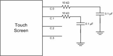
The touch screen hardware works exactly as described in the Handwriting Recognition System project. The only changes that were made to their setup was the removal of the amplifier, which we felt was unnecessary, and changing the resistors and capacitors so that the cutoff frequency would be 159.155Hz. The touch screen will output voltages that are based on where the user is touching the screen. When Vcc is applied to the 3rd wire and ground applied to the 1st wire, the remaining wires will give a voltage that corresponds to the Y coordinate, which is fed into the ADC to be read as a value from 0 to 255. When the 4th and 2nd wire are fed to Vcc and ground, respectively, voltage readouts will correspond to the X coordinates.
Transmitter and
Receiver


The circuits for the RCT-433 transmitter and the RCR-433 receiver were taken from Donn Kim’s and Antonio Dorset’s “Dual Control R/C Car” project and they are unmodified.
Results
Most goals set out for this project were ultimately achieved, although a critical component, the RF transmission and receiving to control the car itself, refused to work properly until a mere hour before the start of our lab period. The user touch screen control unit worked flawlessly, transmitting the correct directions and speed. We verified this by reading the data packets with Meghan Desai’s reference receiver unit. Essentially all hardware was in fully functioning order, and the only problems were software based. All hardware was very thoroughly tested and indeed the transmitted signal was being correctly and effectively received by the car, but the signal itself refused to be properly processed to final control signals for the car until the very last moments before demonstration. Our problem We thus had little time to test out other aspects of the car that were buggy such as stopping the power motors from running and getting the car to run in reverse.
Essentially 95% of our project worked flawlessly, but the single RF component flaw ultimately prevented our design from being fully implemented. The problem was resolved mere hours before our demonstration time, and this did not give sufficient time to truly test out the car.
With respect to timing issues, all necessary calculations that were involved on the user end control module was computed within the allotted time between grabbing successive points. The calculated turn angles and speeds all seemed reasonable, and essentially the control module worked to exact specifications.
Although we were not the only group utilizing RF, we generally did not encounter any interference during testing.
Conclusions
In general, what ultimately made the project novel, the unique user control unit, was successfully created and tested. What we did not anticipate were the hellish issues that we encountered with the RF transmission. We assumed that since it was so well documented, and widely used that it would be the least of our worries in this project. Essentially, the pieces that are unique to our project were implemented with compete success. It was purely the components that we borrowed from other projects that failed to work, which made the problem all the more vexing and infuriating. Ultimately, the transmitter issue was fixed, but by then we had so little time left that full testing was effectively impossible. If we had more time, we would have simply implemented a different RF protocol instead of using an existing one.
To the best of our knowledge, all of the claims that we have
made are accurate. Our circuit diagrams
and descriptions match those that we implemented exactly. We have given proper credit for all aspects
of our project which we did not design or design with the help of
Pictures
(Transmitter unit)
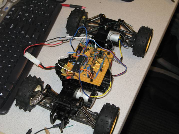
(The car)
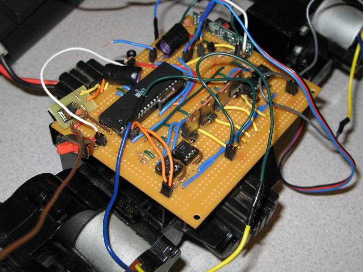
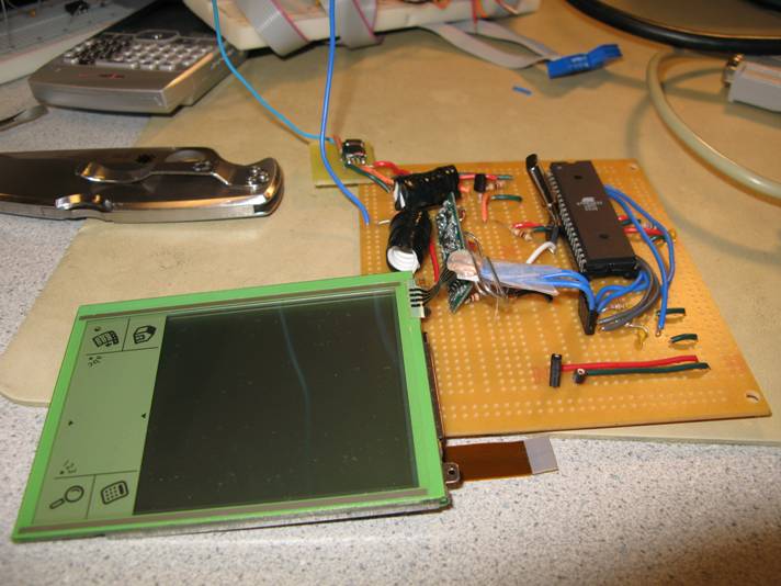
(Close-up of the car circuitry)
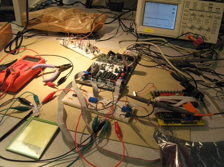
(Development Hell)
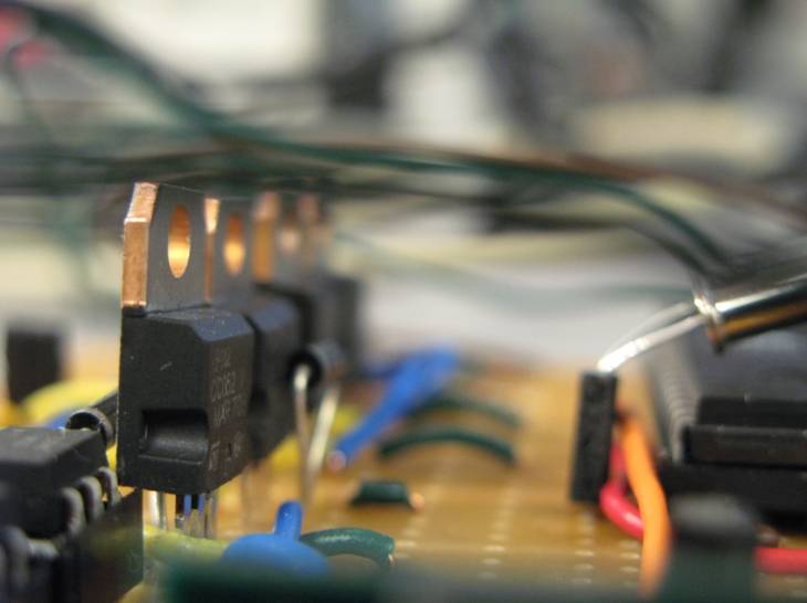
(Lovely macro shot)
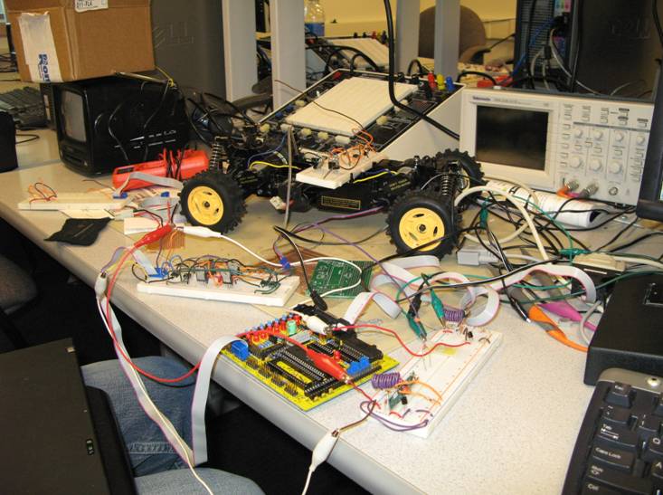
(more of Development Hell)
Appendix: Commented code
////////transmitter unit code/////////////
//
A to D test code
// NOTE -- You MUST MOUNT the Aref
jumper
#include <Mega32.h>
#include <stdio.h>
#include <delay.h>
#include <math.h>
#include<.\txrx_mega32.c>
//I hate these definitions, which
is why I deleted them
#define prepareX 1
#define prepareY 2
#define takeX 3
#define takeY 4
#define data_length 2
#define tx_id 5
#define tx_id_stop 6
//mapping for converint 0-255
values to an X coordinate
flash char Xcoor[256] =
{0,0,0,0,0,0,0,0,0,0,0,0,0,0,0,0,0,0,0,0,0,0,0,0,0,0,0,0,0,0,0,
0,0,0,0,0,0,1,2,3,3,4,5,6,7,8,9,9,10,11,12,13,14,15,15,16,17,
18,19,20,21,21,22,23,24,25,26,27,27,28,29,30,31,32,33,33,34,35,
36,37,38,39,39,40,41,42,43,44,45,45,46,47,48,49,50,51,51,52,53,
54,55,56,57,57,58,59,60,61,62,63,63,64,65,66,67,68,69,69,70,71,
72,73,74,75,76,76,77,78,79,80,81,82,82,83,84,85,86,87,88,88,89,
90,91,92,93,94,94,95,96,97,98,99,100,100,101,102,103,104,105,106,
106,107,108,109,110,111,112,112,113,114,115,116,117,118,118,119,
120,121,122,123,124,124,125,126,127,128,129,130,130,131,132,133,
134,135,136,136,137,138,139,140,141,142,142,143,144,145,255,255,
255,255,255,255,255,255,255,255,255,255,255,255,255,255,255,255,
255,255,255,255,255,255,255,255,255,255,255,255,255,255,255,255,
255,255,255,255,255,255,255,255,255,255,255,255,255,255,255,255};
//Y coordinate mapping
flash char Ycoor[256] =
{0,0,0,0,0,0,0,0,0,0,0,0,0,0,0,0,0,0,0,0,0,0,0,0,0,0,0,0,0,1,2,3,4,
5,6,7,8,9,10,11,12,13,14,15,16,17,18,19,20,21,22,23,24,25,26,27,28,
29,30,31,32,33,34,35,36,37,38,39,40,41,42,43,44,45,46,47,48,49,50,
51,52,53,54,55,56,57,58,59,60,61,62,63,64,65,66,67,68,69,70,71,72,
73,74,75,76,77,78,79,80,81,82,83,84,85,86,87,88,89,90,91,92,93,94,
95,96,97,98,99,100,101,102,103,104,105,106,107,108,109,110,111,112,
113,114,115,116,117,118,119,120,121,122,123,124,125,126,127,128,129,
130,131,132,133,134,135,136,137,138,139,140,141,142,143,144,145,146,
147,148,149,150,151,152,153,154,155,156,157,158,159,160,161,162,163,
164,165,166,167,168,169,170,171,172,173,174,175,176,177,178,179,180,
181,182,183,184,185,186,187,188,189,190,255,255,255,255,255,255,255,
255,255,255,255,255,255,255,255,255,255,255,255,255,255,255,255,255,
255,255,255,255,255,255,255,255,255,255,255,255,255};
//translation table to translate angles to the final signals
needed to conrol the servo properly
flash char finalmovement[109] =
{51,51,52,52,52,53,53,53,54,54,54,54,55,55,55,56,56,56,57,57,57,58,58,58, //24
59,59,59,60,60,60,60,61,61,61,62,62,62,63,63,63,64,64,64,65,65,65,65,66,66,//25
66,67,67,67,68,68,68,69,69,69,70,70,70,71,71,71,71,72,72,72,73,73,73,74,74,//25
74,75,75,75,76,76,76,77,77,77,77,78,78,78,79,79,79,80,80,80,81,81,81,82,82,
82,82,83,83,83,84,84,84,85,85};
//a simple table of squared values
flash unsigned int squared[101] =
{0,1,4,9,16,25,36,49,64,81,100,121,144,169,196,225,256,289,324,361,400,441,484,529,576,625,676,729,784,841,900,961,1024,1089,1156,1225,1296,1369,1444,1521,1600,1681,1764,1849,1936,2025,2116,2209,2304,2401,2500,2601,2704,2809,2916,3025,3136,3249,3364,3481,3600,3721,3844,3969,4096,4225,4356,4489,4624,4761,4900,5041,5184,5329,5476,5625,5776,5929,6084,6241,6400,6561,6724,6889,7056,7225,7396,7569,7744,7921,8100,8281,8464,8649,8836,9025,9216,9409,9604,9801,10000};
//translates a value to the final speed amount we want
flash char rootedSPEED[201] =
{0,4,6,7,8,9,10,10,10,10,10,10,10,10,10,10,10,10,10,10,10,
10,10,10,10,10,10,10,10,10,10,10,10,10,10,10,10,10,10,10,
10,10,10,10,10,10,10,10,10,10,10,10,10,10,10,10,10,10,10,
10,10,10,10,10,10,10,10,10,10,10,10,10,10,10,10,10,10,10,
10,10,10,10,10,10,10,10,10,10,10,10,10,10,10,10,10,10,10,
10,10,10,10,10,10,10,10,10,10,10,10,10,10,10,10,10,10,10,
10,10,10,10,10,10,10,10,10,10,10,10,10,10,10,10,10,10,10,
10,10,10,10,10,10,10,10,10,10,10,10,10,10,10,10,10,10,10,
10,10,10,10,10,10,10,10,10,10,10,10,10,10,10,10,10,10,10,
10,10,10,10,10,10,10,10,10,10,10,10,10,10,10,10,10,10,10,10,10,10,10,10,10,10,10,10};
int c =
0;
int d =
0;
char i =
0;
unsigned char COORstate;
int sum =
0;
//for angle calculation
int averagedX = 0;
int averagedY = 0;
int averagedX_p = 0;
int averagedY_p = 0;
int averagedX_pp = 0;
int averagedY_pp = 0;
char backingup
= 0;
char validangle
= 0;
int howmanypoints = 0;
char Xang_12,Yang_12,Xang_23,Yang_23,Xang_13,Yang_13;//angles
for backup detection
int
dist_12,dist_23,dist_13;
int signey = 0;;
//int averagedX_pp
= 0;
//int averagedY_pp
= 0;
unsigned char once = 1;
int slope
= 0;
signed char olddegree
= 0;
signed char degree = 0;
signed int
moveangle = 0;
unsigned char final_tick
= 0;
unsigned char data[2];
unsigned char spandd;
void initialize(void);
void coordinate(void);
void getspeed(void);
void getangle(void);
unsigned char started = 0;
unsigned char
anglecoorX,anglecoorY,anglecoorX_p,anglecoorY_p,anglecoorX_pp,anglecoorY_pp;
//moving array of last 15 points
unsigned char groupanglecoorX[15]
= {0};
unsigned char groupanglecoorY[15]
= {0};
unsigned char Xcoord_ppp
= 0;
unsigned char Ycoord_ppp
= 0;
unsigned char Xcoord_pp
= 0;
unsigned char Ycoord_pp
= 0;
unsigned char Xcoord_p
= 0;
unsigned char Ycoord_p
= 0;
unsigned char Xcoord
= 0;
unsigned char Ycoord
= 0;
unsigned char packet_count
= 0;
char Xleast,Xmid,Xcur,Yleast,Ymid,Ycur,cur_speed,
mid_speed, least_speed;
int final_speed = 0;
interrupt [TIM0_COMP] void sgen(void){
++c;
++d;
coordinate();
}
int test;
void main(void){
initialize();
while (1) {
if(ready == 1){
if (Xcoord == 0 && Ycoord ==
0) once = 1;
else if( Xcoord != 0 && Ycoord != 0){//only if there is a valid coordinate being
read
if(once == 1)
{//sets the initial conditions for when the stylus first touches the screen
PORTD.7 = PORTD.7 ^ 1;
once = 0;
averagedX = Xcoord;
averagedY = 4;
averagedX_p = Xcoord;
averagedY_p = 0;
final_tick = 68;
howmanypoints = 0;
cur_speed = 0;
mid_speed = 0;
backup = 0;
least_speed = 0;
Xcur = Xcoord;
Xmid = Xcoord;
Xleast = Xcoord;
Ycur = Ycoord;
Ymid = Ycoord;
Yleast = Ycoord;
}
//printf("%d,%d\n\r",Xcoord, Ycoord);
getspeed();//calculates speed
test = final_speed;
//printf("%d,
%d, %d\n\r",test, moveangle,
backingup);
if(howmanypoints > 15){//runs
only ever 15 points
getangle();
howmanypoints = 0;
//printf("(%d, %d) %d,
%d, %d, %d\n\r",averagedX, averagedY,
slope, degree,moveangle, backingup);
}
if(backingup == 1) {
spandd = 0b10000000 | final_speed;
}
else spandd = final_speed;//transmit
code, but only if valid
data[0] = spandd;
data[1] = final_tick-19;
//printf("%d,
%d, %d\n\r", data[0], data[1], moveangle);
if(validangle == 1) tx_me(data, data_length, tx_id);
else {//transmit zero speed and neutral angle when invalid
data[0] = 0;
data[1] = 48;
tx_me(data,
data_length, tx_id);
}
}
ready = 0;
}else{
final_speed = 0;
}
}
}//3249
void
initialize(void){//initializations
//init the A to D
converter
//channel zero/
left adj /EXTERNAL Aref
//!!!CONNECT Aref jumper!!!!
//ADMUX =
0b00100000;
DDRD.7 = 1;
DDRC = 0b00001010;
//Set PORTC.1 and PORTC.3 to outputs
PORTC = 0b00001000;
//pull everything to GND except PORTC.3 for reading X
ADMUX = 0b00100000;
//start conversion
ADCSRA =
0b11000101;
//timer stuff
TIMSK=2;
OCR0 = 250;
TCCR0 = 0b00001011;
txrx_init(1,0,416,1); //TX only -
4000 baud - led on
#asm
sei
#endasm
//init the UART
//UCSRB = 0x18;
//UBRRL = 103;
//printf("starting...\n\r");
// measure and
display loop
COORstate
= prepareX;
ready
= 0;
anglecoorX = 0;
anglecoorY = 0;
anglecoorX_p
= 0;
anglecoorY_p
= 0;
anglecoorX_pp
= 0;
anglecoorY_pp
= 0;
}
void coordinate(void){//this is a
state machine that grabs the coordinates.
it is run every milisecond
in the interrupt
switch(COORstate){
case prepareX ://prepare the ports
to get the X coordinates
if(d > 15 && ready == 0){ //specifying frequency of points taken per
sec
DDRC = 0b00001010;
//Set PORTC.1 and PORTC.3 to outputs
PORTC =
0b00001000; //pull everything to GND except PORTC.3 for reading X
ADMUX =
0b00100000;
COORstate = takeX;
c
= 0;
}
break;
case takeX :
if(c>7){//ait 7 milliseconds
and then get them
if(started == 0) {
ADCSR.6=1;
//printf("%d\n\r",Ycoord);
//delay_us(4);
started = 1;
for(i=0; i<14; i++){
groupanglecoorX[i+1] = groupanglecoorX[i];
}
}
if(ADCSR.6 == 0) {
started = 0;
Xcoord_ppp = Xcoord_pp;
Xcoord_pp = Xcoord_p;
Xcoord_p = Xcoord;
Xcoord = Xcoor[ADCH];
groupanglecoorX[0] = Xcoord;
COORstate = prepareY;
}
}
break;
case prepareY ://prepare ports to
get y axis
DDRC
= 0b00000101; //Set PORTC.0 and PORTC.2 to outputs
PORTC
= 0b00000100; //pull everything to GND except PORTC.2 for reading Y
ADMUX
= 0b00100001;
COORstate
= takeY;
c = 0;
break;
case takeY :
if(c>7){
if(started
== 0) {
started = 1;
ADCSR.6=1;
//printf("%d,",Xcoord);
//delay_us(4);
for(i=0; i<14;
i++){
groupanglecoorY[i+1]
= groupanglecoorY[i];
}
}
if(ADCSR.6 == 0) {
started = 0;
Ycoord_ppp = Ycoord_pp;
Ycoord_pp = Ycoord_p;
Ycoord_p = Ycoord;
Ycoord = Ycoor[ADCH];
groupanglecoorY[0]
= Ycoord;
c
= 0;
COORstate = prepareX;
d
= 0;
ready = 1;
howmanypoints++;
}
}
break;
}
}
void getspeed(void){//this
function extrapolates the current speed by averaging the distances of the
current coordinate and the last two
if(Xcoord > Xcoord_p){//making
sure that the index for the square table is positive
Xcur = Xcoord - Xcoord_p;
}else{
Xcur = Xcoord_p - Xcoord;
}
if(Ycoord > Ycoord_p){
Ycur = Ycoord - Ycoord_p;
}else{
Ycur = Ycoord_p - Ycoord;
}
if(Xcoord_p > Xcoord_pp){
Xmid = Xcoord_p - Xcoord_pp;
}else{
Xmid = Xcoord_pp - Xcoord_p;
}
if(Ycoord_p > Ycoord_pp){
Ymid = Ycoord_p - Ycoord_pp;
}else{
Ymid = Ycoord_pp - Ycoord_p;
}
if(Xcoord_pp > Xcoord_ppp){
Xleast = Xcoord_pp - Xcoord_ppp;
}else{
Xleast = Xcoord_ppp - Xcoord_pp;
}
if(Ycoord_pp > Ycoord_ppp){
Yleast = Ycoord_pp - Ycoord_ppp;
}else{
Yleast = Ycoord_ppp - Ycoord_pp;
}
if(~(Xcur > 10 || Ycur > 10 || Xmid > 10 || Ymid > 10 || Xleast > 10 || Yleast >
10)){//only produce a valid speed if the average is less than 10 pixels in
distance
cur_speed = rootedSPEED[squared[Xcur] + squared[Ycur]];
mid_speed = rootedSPEED[squared[Xmid] + squared[Ymid]];
least_speed = rootedSPEED[squared[Xleast] + squared[Yleast]];
final_speed =
((float)(cur_speed + mid_speed + least_speed))/3;
if(final_speed != 0) final_speed += 5;
if(validangle != 1) final_speed == 0;
}
}
void getangle(void){//gets
the angle through the averaged points
sum = 0;
for(i=0;i<15;i++){//average the
current set of 15 points
sum = sum + groupanglecoorX[i];
}
averagedX_pp = averagedX_p;
averagedX_p = averagedX;
averagedX = ((float)sum)/15;
sum = 0;
for(i=0;i<15;i++){
sum = sum + groupanglecoorY[i];
}
averagedY_pp = averagedY_p;
averagedY_p = averagedY;
averagedY = ((float)sum)/15;
sum = 0;
olddegree = degree;//degree
shifting
if((averagedY_p - averagedY) != 0){
slope = 1000*(((float)(averagedX_p
- averagedX))/((float)(averagedY_p
- averagedY)));
signey = 0;
if(slope < 0){
slope = (slope ^ 0xffff) + 1;
signey = 1;
}
}else if(averagedY_p == averagedY && averagedX_p
> averagedX){
slope = 28001;
signey = 1;
}else{
slope = 28001;
}
if(slope < 35){//this is essentially going to get an
angle reading from the slope
degree = 0;
}else if(slope < 87){
degree = 5;
}else if(slope < 141){
degree = 8;
}else if(slope < 194){
degree = 11;
}else if(slope < 249){
degree = 14;
}else if(slope < 306){
degree = 17;
}else if(slope < 364){
degree = 20;
}else if(slope < 424){
degree = 23;
}else if(slope < 488){
degree = 26;
}else if(slope < 554){
degree = 29;
}else if(slope < 625){
degree = 32;
}else if(slope < 700){
degree = 35;
}else if(slope < 781){
degree = 38;
}else if(slope < 869){
degree = 41;
}else if(slope < 966){
degree = 44;
}else if(slope < 1072){
degree = 47;
}else if(slope < 1192){
degree = 50;
}else if(slope < 1327){
degree = 53;
}else if(slope < 1483){
degree = 56;
}else if(slope < 1664){
degree = 59;
}else if(slope < 1881){
degree = 62;
}else if(slope < 2145){
degree = 65;
}else if(slope < 2475){
degree = 68;
}else if(slope < 2904){
degree = 71;
}else if(slope < 3487){
degree = 74;
}else if(slope < 4331){
degree = 77;
}else if(slope < 5671){
degree = 80;
}else if(slope < 8144){
degree = 83;
}else if(slope < 14300){
degree = 86;
}else{
degree = 90;
}
if(signey == 1){//is it a negative
angle?
degree = (degree ^ 0xff) + 1;
}
//for the
Xs
if(averagedX > averagedX_p){
Xang_23
= averagedX - averagedX_p;
}else{
Xang_23
= averagedX_p - averagedX;
}
if(averagedX_p > averagedX_pp){
Xang_12
= averagedX_p - averagedX_pp;
}else{
Xang_12
= averagedX_pp - averagedX_p;
}
if(averagedX > averagedX_pp){
Xang_13
= averagedX - averagedX_pp;
}else{
Xang_13
= averagedX_pp - averagedX;
}
//for the Ys
if(averagedY > averagedY_p){
Yang_23
= averagedY - averagedY_p;
}else{
Yang_23
= averagedY_p - averagedY;
}
if(averagedY_p > averagedY_pp){
Yang_12
= averagedY_p - averagedY_pp;
}else{
Yang_12
= averagedY_pp - averagedY_p;
}
if(averagedY > averagedY_pp){
Yang_13
= averagedY - averagedY_pp;
}else{
Yang_13
= averagedY_pp - averagedY;
}
//for the
final distances for detecting backing up
dist_12 = squared[Yang_12] + squared[Xang_12];
dist_23 = squared[Yang_23] + squared[Xang_23];
dist_13 = squared[Yang_13] + squared[Xang_13];
if(dist_13 < dist_12 || dist_13 < dist_23) {
backingup = backingup
^ 1;
}
moveangle = degree - olddegree;
if(backingup == 1){
moveangle = (moveangle
^ 0xffff) + 1;
}
//an error
compensation that is inherent in the algorithm
if(averagedY_p > averagedY_pp && averagedY_p
> averagedY && backingup
== 0){
moveangle = (180 + degree) - olddegree;
}
//correct
the moveangle value so that it can access a table for
the correct signal to be sent to the car
if(moveangle < 55 && moveangle > -55){
validangle = 1;
final_tick = finalmovement[moveangle+54];
}else{
validangle = 0;
}
}
//Receive Unit
//Includes
#include<mega32.h>
#include<delay.h>
#include<.\txrx_mega32.c>
#include <stdio.h>
//definitions
#define begin {
#define end }
#define MAX_RX_LENGTH 10
#define data_buffer 32
//declarations
char done;
char my_rx_data[MAX_RX_LENGTH];
char k;
int servoTime = 0;
int stopServo = 49; //max right hand turn = 66, max left hand
turn = 32
char duty = 0;
char dcTime
= 1;
char backup = 0;
/* PORT ASSIGNMENTS
D.0 = RF Receive
D.1 = RF Transmit
B.0 = Servo control
B.1 = Forward control
B.2 = Reverse control
*/
void goforward(void);
void backsup(void);
void stop(void);
//**********************************************************
//timer 0 compare ISR
interrupt [TIM0_COMP] void
timer0_compare(void) {
servoTime++;
if(servoTime == stopServo) {
PORTB.0 = 0;
}
if(servoTime == 1000) {
PORTB.0 = 1;
servoTime = 0;
}
}
//**********************************************************
//timer 1 compare ISR
interrupt [TIM1_COMPA] void
timer1_compare(void) {
dcTime++;
if((dcTime == 20 && backup == 0) && duty != 0)
{
dcTime = 1;
goforward();
}
if((dcTime == 20 && backup == 1) && duty != 0)
{
dcTime = 1;
backsup();
}
if(duty
== 0 || (dcTime == duty && duty != 20)) {
stop();
}
}
void goforward(void)
{
PORTB.2 = 0;
PORTB.1 = 1;
}
void backsup(void)
{
PORTB.1 = 0;
PORTB.2 = 1;
}
void stop(void) {
PORTB.1 = 0;
PORTB.2 = 0;
}
//**********************************************************
//initialization
void init()
begin
//Set up motor
ports
DDRB = 0xff;
PORTB.0 = 1;
PORTB.1 = 1;
DDRC = 0xff;
PORTC.0 = 0;
//set up timer 0
TIMSK=0b00010010; //turn on timer 0 cmp match ISR
OCR0 = 4;
TCCR0=0b00001011; //prescalar
to 64 and turn on clear-on-match
//set up timer 1, 1/10 msec
TCCR1A = 0b00000000;
TCCR1B =
0b00001011;
OCR1A= 25;
//OCR1AL = 0;
//TXRX init
txrx_init(0,1,249,1);//RX only -
4000 baud - led on
PORTD.1 =1;
rx_reset(MAX_RX_LENGTH);
done
= 0;
#asm ("sei");
end
//**********************************************************
void main()
{
init();
while(1) {
if(rxdone()==1) {
PORTB.3 =
PORTB.3^1;
k=0;
init_getrx();
while(rx_empty()!=1) {
my_rx_data[k] = get_next_rx_data();
k++;
}
// 0 - 170
// 1 - start_char
// 2 - ID
// 3 -
length
// 4 -
number
// 5 -
Forward/Reverse and speed
// 6 -
Turning radius
//Extract
whether travelling forward or reverse and speed
if((0b01111111 | my_rx_data[5]) ==
0xff) {
my_rx_data[5] = my_rx_data[5] &
0b01111111; //Clear top bit if necessary
backup = 1;
}
else backup = 0;
duty = my_rx_data[5];
//Extract
turning radius
stopServo = my_rx_data[6
];
rx_reset(MAX_RX_LENGTH);
}
} //while
} //main
Appendix: Schematics
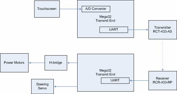
(High level schematic)
(H-bridge schematic)
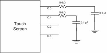
(touch screen schematic)
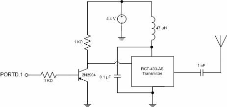
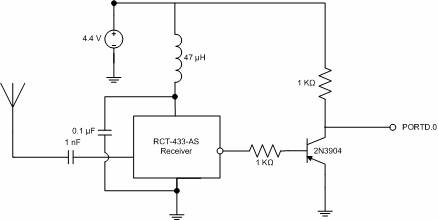
(RF transmitter and receiver schematic)
Appendix: cost of components
|
Quantity |
Part |
Cost |
|
2 |
Mega32 microcontrollers: |
$0, sampled from Avnet, Inc. |
|
1 |
RF transmitter and receiver pair: |
$0, sampled from Radiotronix |
|
1 |
Radioshack Black Phantom RC car |
$0, donated by a friend |
|
2 |
TIP105 and 2 TIP107 transistors: |
$0.90 |
|
1 |
Servo motor: |
$14.00 |
|
4 |
Optoisolators: |
$1.20 |
|
2 |
40-pin DIP sockets: |
$1.00 |
|
4 |
8-pin DIP sockets: |
$0.80 |
|
2 |
Solder boards: |
$5.00 |
|
6 |
AA batteries |
$5.15 |
|
|
|
Total: $28.50 |
Appendix: Work division
Tytus Mak
- H-bridge design
- Touch screen implementation
- Speed and direction algorithm development and implementation in code
Dan DiBernardo
- Principle code debugging
- Car control signal code
- Principle soldering
- RF transmission
References
- TIP102 datasheet - http://pubpages.unh.edu/~aperkins/pdf/TIP-devices/TIP102.pdf
- TIP105 datasheet - http://www.ortodoxism.ro/datasheets/stmicroelectronics/5261.pdf
- Meghan Desai’s RF protocol - http://instruct1.cit.cornell.edu/courses/eceprojectsland/STUDENTPROJ/2005to2006/mpd25/report.html
- Handwriting Recognition system - http://instruct1.cit.cornell.edu/courses/ee476/FinalProjects/s2006/gh75/web/index.html
- Servo - http://www2.towerhobbies.com/cgi-bin/WTI0001P?&I=LX0929
- Radiotronix transmitter - http://www.radiotronix.com/datasheets/RCT-433-AS.pdf
- Radiotronix receiver - http://www.radiotronix.com/datasheets/rcr433rp.pdf