uControl
Sam Fladung (saf37)
Gary Soedarsono (gs243)
Monday 4:30
Final Project
April 2, 9, 16, 23, 30, 2007
1. Contents
3.3. Hardware
/ Software Tradeoff
3.4. Relationship
to Standards
3.5. Existing
Patents and Trademarks
7.3. Intellectual
Property Considerations
8.4. Tasks of
Each Group Member
2. Introduction
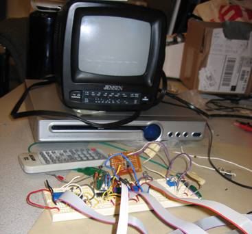
This project creates a programmable device that can control a DVD
player on scheduled times by sending infrared signals.
The uControl allows the user to control their DVD player as if they are
using a remote control. However, unlike remote controls, uControl allows the
user to program a sequence of button pushes that will automatically run at a
time that they can set. To schedule the sequence of button pushes, the user can
use the computer to program the device, or use their remote control to have the
device record the sequence of button pushes. These are done after setting the
execution time of the button push sequence. When the time arrives, the device
will automatically execute this sequence of button pushes.
3. High Level Design
3.1. Rationale
3.2. Logical Structure
The project was completed in several stages. We started by implementing
the most crucial elements of uControl: the EEPROM and the IR Photo Detector.
The EEPROM was used for storing scheduled events. The IR Photo Detector was
used for detecting the type of signal emitted by the DVD Player remote control,
so that we can learn the bit pattern for each button press and the format of
the infrared signal. Once we got the EEPROM to receive and transmit data, and the
IR Photo Detector to read IR signal from the remote control, we implemented the
infrared LED. Finally, we implemented the real time clock.
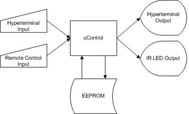
Figure 1 - Overall Input / Output of Project
The hyperterminal input is the main way for user to interact with the device. By entering Unix like commands, the user can control the DVD player, edit the event scheduling, as well as edit the setting of the device. The remote control input is used only when recording a scheduled event. When the user creates a new scheduled event, they must specify the actions to be taken. One way to do this is by entering commands corresponding to each action. However, since this method can be tedious, an alternative way would be to use the remote control to enter the actions.
The hyperterminal output is mainly used for feedback to the user after they have entered a command. The IR LED Output is used to control the DVD Player by sending the same signal that the remote control of the DVD Player would send.
The EEPROM is used to store scheduled events. uControl periodically checks EEPROM for events to be run, and make add or remove events by the user’s request.
3.3. Hardware / Software Tradeoff
One of the tradeoffs was whether to handle modulating the IR LED using the AtMega, or a separate frequency generator. Since the CTC timer on the AtMega allowed us to generate approximately the correct waveform without any additional hardware we chose to use it. Also, we had to choose whther to keep track of times on the AtMega, or whether to use an external clock. Because we wanted the device to continue functioning when power was removed, we chose to us an RTC (DS1305) with a backup battery.
3.4. Relationship to Standards
There are several standards for Infrared remote communications. Most
use a byte based code that is modulated on top of a 30-40Khz carrier wave. To
find out the protocol of the signal, we connect an oscilloscope to the output
of the IR photodetector and analyze the signal for a button press of the remote
control. Any signal sent by the remote control contains three main parts:
header, body, and trigger. A bit 0 is represented by 600µs high pulse followed
by 500µs low pulse. A bit 1 is represented by 600µs high pulse followed by
1.6ms low pulse.
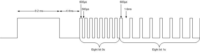
Figure 2 – Annotated Header Part of the IR
Signal
The header part starts with a 9.2 ms of high signal, followed by 4.4 ms
of low signal. After this, eight bit 0 are sent, followed by eight bit 1s.
The body part contains 16 bits of instruction in binary format, each
corresponding to a button on the remote control. This part is followed by 39.9
ms of low signal, before the trigger part.
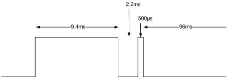
Figure 3 - Annotated Trigger Part of the
IR Signal
The trigger part consists of 9.4 ms of high signal, followed by 2.2 ms
of low pulse, 600µs of high pulse, and 96 ms of low pulse. When a button on the
remote control is held down, the remote control only send the header and body
once, and the trigger part is send multiple times, once for each repetition.
In addition to the standard RS-232 Serial that we have used in previous
labs, this project makes use of two synchronous serial busses. These two busses
(I2C and SPI) both clock data one bit at a time. Serial Peripheral Interface
(SPI) uses a chip select line to control which chip on the bus the master is
talking to. It also allows full duplex communication with the master talking on
Master Out Slave In (MOSI) and the slave talking on Master In Slave Out (MISO).
Every time the master drives the clock, one bit of data is transmitted in each
direction. I2C uses only 2 wires for both addressing and sending data. This
works by first sending an address byte to indicate which slave device is being
addressed. The master can then either clock data in or out (but not both at the
same time). I2C is a protocol developed by Phillips Semiconductors.
3.5. Existing Patents and Trademarks
The following are patents related to the device that have not expired:
· Patent 6989763: Web-based universal remote control (2006)
· Patent 5691710: Self Learning Infrared Remote Control Transmitter (1997)
· Patent 5684471: Infrared Remote Control Transmitter with Power Saving Feature (1997)
The following patents are related, but they have already expired (at
least 20 years old):
·
Patent
4425647: Infrared Remote Control System (1984)
·
Patent
4426662: Infrared Remote Control Detector / Decoder (1984)
·
Patent
4377006: Infrared Remote Control System (1983)
4. Program Details
The software consists of seven main parts:
1. The Serial Communicator is responsible for sending and receiving messages from the hyperterminal.
2. The Parser is the main part of the program. It is responsible for interpreting the commands sent by the user through the hyperterminal and executing them. This means that it is also responsible for controlling the real time clock, the EEPROM, and the IR LED. It also process the IR LED input signals after the IR Receiver has converted it to binary code.
3. The CLK & SPI Protocol act as interface to the real time clock for the rest of the device. It allows other modules of the program to read and set values to the real time clock.
4. The IR Receiver converts the analogue IR signal to digital form to make sure that other modules can use the signal.
5. The Event Runner periodically checks the EEPROM if there are any scheduled events that need to be run.
6. The TWI Protocol, like the SPI Protocol, acts as an interface to the EEPROM.
7. The IR Transmitter transmits any bit patterns using the IR LED after formatting the bit pattern to the correct IR Signal form, as outlined in section 3.4.

Figure 4 - Diagram Showing Overall Working of the Software
4.1. Serial Communicator
This part follows the same scheme as the one used in Lab 3: Security Systems. The scheme follows as outlined ECE 476 Website, and the implementation is a modified version of the example given in that page.
4.2. Parser
The parser periodically checks if the user has entered any commands, and executes the command once it detects any commands from the user. The available commands and their formats are listed in Table 1 - Table of Commands and Their Formats..
|
|
Command |
Format |
Description |
|
DVD Player Control |
vol+ |
- |
Increment
Volume |
|
vol- |
- |
Decrement
Volume |
|
|
pow |
- |
Turn
on / off DVD Player |
|
|
mut |
- |
Mute
/ Unmute DVD Player |
|
|
play |
- |
Play |
|
|
stop |
- |
Stop |
|
|
pause |
- |
Pause
/ Resume |
|
|
prev |
- |
Previous |
|
|
next |
- |
Next |
|
|
disc |
- |
Open
/ |
|
|
Events |
evnew |
<time>
<name> |
Create
new events |
|
evdel |
<addr> |
Delete
event from EEPROM |
|
|
evfin |
- |
Finish
recording event |
|
|
evls |
- |
List
events in EEPROM |
|
|
Time |
sync |
<time> |
Set
time of real time clock |
|
time |
- |
Print time of real time clock |
Table 1 - Table of Commands and Their Formats.
NOTE: <time> is specified as seconds, minutes,
hours, date, month, and year.
<name> is 5 characters long.
<addr> is address shown when executing evls
The parser can run in two modes:
To make saving events easy and fast, we split the EEPROM into blocks of 32 bytes. The content of the block is outlined in Table 2.
|
Bytes |
Description |
|
0 |
0x00
for valid block, 0x01 for invalid / empty block |
|
1…5 |
5
characters long name of the event |
|
6…11 |
Time
that the event should be executed. In order of increasing byte: second, minute,
hour, day, month, year |
|
12…31 |
A sequence of at most 10 button presses. 0
indicates no button press |
Table 2 - Content of an Event Block in the EEPROM
When initializing the parser, the program scans the EEPROM while looking for the last event block that is empty / invalid. This address is saved, and it is assumed that any blocks with address less than this address are not empty. This makes writing new events to EEPROM very easy; the program only needs to write to the location pointed by the saved event address, and then move the saved address forward by one. When an event is deleted, to make sure that the assumption is still correct, another event block needs to be moved to the location where an event was deleted. A way to do this would be to move the last event in the EEPROM to this location. While this destroys temporal locality in the data structure, this method is much faster than having to move a large number of blocks, especially since writing to EEPROM requires at least 5 ms delay before the next write. Without this delay, the next writing to EEPROM will not occur.
Since writing to EEPROM needs at least 5 ms delay, commands that involve writing to EEPROM must implement a delay scheme. This delay scheme must allow other state machines to run during the delay. This is especially important for the IR Transmit state machine, since stopping the state machine will mess up the timing for the signal, thus distorting the IR signal. The delay scheme is implemented by using another state in the parser state machine. Whenever a delay is needed, the state machine sets the next state that it should go to after the delay, and enters the delay state. After 5 ms of delay in the delay state, the state machine goes to the state that has been set before entering the delay state. This way, 5 ms of delay can be provided after writing and reading from EEPROM without blocking other state machines.
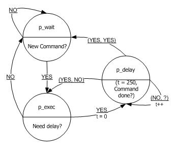
Figure 5 - Simplified Diagram of the Parser's State Machine (State Transition Time: 20μs)
The parser also needs to take into account the delay caused by reading and writing into the real time clock. Since the read and write methods are blocking, we need to make sure that the IR Transmitter is not transmitting anything before reading or writing into the real time clock. So, the state machine will wait until the transmit buffer of the IR Transmitter is emptied before executing these commands.
4.1. CLK & SPI Protocol
The spi part of the software handles reading and writing into the real time clock using the Serial Peripheral Interface (SPI) as outlined in ECE 476 Website. There are three main methods in the SPI part: initialization, write, and read from the real time clock. We used the spi method form the SPI library that comes with CodeVision to implement this part.
Following the scheme outlined in the real time clock’s datasheet, we implemented the write method by first setting the real time clock’s cm pin to high, then sending two 8 bit characters, followed by setting the real time clock’s cm to low. The first 8 bit sent is the address in the real time clock to write onto. The second 8 bit character is the value that the referred address should be set to.
Following the same scheme, the read method is implemented by first setting the cm to high, sending one 8 bit character, receiving 8 bit characters, setting the cm back to low, and returning the received 8 bit character. Like in sending, the 8 bit character sent is the address to read from. To read value from the real time clock, we used the fact that the spi method also returns the value received. So, after sending the 8 bit address, we send a junk value using the spi method and keep the returned value from that method.
Since the time values are kept in the real time clock in an unconventional way, we used the CLK (clock) part to handle the conversion between the format used in the real time clock and the normal format. The real time clock uses 8 bit characters to store the values of the time parameters. The highest four bits represent the 10s of the value, and the rest are the 1s. This means that 23 is stored as 0b00100011, instead of 0b00010111. Also, bit 6 of the hour value is used to indicate if the hour is represented in 12 format (with bit 5 being used for AM / PM) or 24 format (bit 5 is used as an extra bit to represent 20 – 23). For this project, the 24 hours format is used. The CLK part acts as an interface to the rest of the program when trying to read / write into the real time clock, so that other parts of the software do not need to deal with the different representation of number in the real time clock.
4.2. IR Receiver
The IR Receiver consists of two parts. The first part utilizes an external interrupt and Timer 1 running with prescaler of 64 to measure the time that the IR Signal from the photo detector is high. When the external interrupt detects a rising edge, it resets the counter of timer 1 (TCNT1) to zero. At this point, timer 1 will keep increasing its counter. When the external interrupt detects a falling edge, it reads off the counter value of timer 1 and adds this value to a receive buffer. This value represents the time that the signal is at a high state.
After filling 33 values to the receive buffer, the second part of the IR Receiver which keeps polling the receive buffer every 20μs will take the values stored in the receive buffer and translate them to a series of ones and zeros. First, it checks if the signal is valid by checking for the header part of the signal, as shown in Figure 2. If the signal passes this check, it will be converted to a series of ones and zeros. Because of noise, the timings cannot be exact. So, we used a range of time to check for the time period, by checking if a time falls within a certain range of time.
4.3. Event Runner
The Event Runner state machine has only two states. In the waitEvent state, it goes through all valid entries in the EEPROM, reading data from the EEPROM only when the infrared’s transmit buffer is empty. This is because when it reads from EEPROM, the even runner also needs to read from the real time clock to check if the saved event in the EEPROM should currently be run. As have been discussed, obtaining current time from the real time clock uses a blocking method. So, to avoid disrupting any IR Transmits, the state machine must make sure that the transmit buffer is empty.
If it is time for the checked event to be run, the Event Runner will switch state to waitBuffer. In this state, it waits for the transmit buffer to be emptied, not only because the executed event will be deleted from the EEPROM and this will need some delay, but also because it needs to make sure that there is enough place in the buffer to place instructions to be sent. Once the transmit buffer is empty, the Event Runner will read all 10 button pushes saved in the event and add all of them to the transmit buffer. Then, to avoid rerunning the same event, the event is deleted from the EEPROM.
4.4. TWI Protocol
To implement the Two Wire Interface (TWI), we used the scheme outlined in the Mega32 Datasheet. To communicate with the EEPROM, we used the scheme outlined in its datasheet, as shown in Figure 6 and Figure 7.
Figure 6 - Protocol to Write a Byte to EEPROM (Source: AA1025 Datasheet)
As illustrated in Figure 6, to send a byte of data to the EEPROM, we have to:
- Send a start signal
- Send the control byte
- Send top half of the address to be written onto
- Send bottom half of the address to be written onto
- Send the 8 bit data
- Send the stop signal
After sending each signal, except for the stop signal, we had to wait for the EEPROM to replay with the ACK signal before proceeding with sending the next signal.

Figure 7 - Protocol to Read a Byte from EEPROM (Source: AA1025 Datasheet)
To read a byte of data from the EEPROM, we had to:
- Send the start signal
- Send the control byte
- Send the top half of the address to be read
- Send the bottom half of the address to be read
- Send another start signal
- Send another control byte
- Wait until data is received
- Send the stop signal
Like when sending data, we had to wait for the EEPROM to replay with the ACK signal before sending the next signal.
4.5. IR Transmitter
The IR Transmitter periodically polls its transmit buffer if it has anything to write. If it does, it will send the 16 bits long codes in the buffer by first sending the header part of the IR Signal as outlined in section 3.4. It uses Timer 2 to generate the signal. Timer 2 is set to run at full speed (no prescaler), toggling OC2 at a frequency of around 38kHz to generate the carrier frequency. To turn off the carrier signal, IR Transmitter can set the TCCR2 register to clear OC2 at compare match. To turn on the carrier signal, IR Transmitter sets the TCCR2 register back to toggling OC2 at compare match. To generate the IR Signal, IR Transmitter only needs to turn on and off the carrier signal at the right times, after the right length of delay.
After the header part has been generated, the transmitter will transmit the 16 bit instruction in the buffer. Since bit 1 and bit 0 both starts with 600μs of high and 500μs of low, the state machine will always start by sending this, even before checking the bit of to be sent.
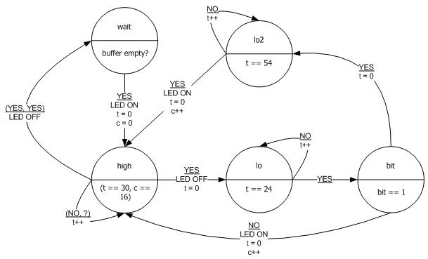
Figure 8 - Simplified State Machine Diagram of the IR Transmit showing only the Body Part. State Transition Time: 20μs
After this, the transmitter will check if the next bit to be sent is a one or a zero. If it is a zero, then the bit has been sent, and the transmitter will send the next bit. If it is a one, then transmitter will wait 1.1 ms longer in the low state before sending the next bit to provide the long low state, the only feature that distinguishes between a bit 1 and a bit 0.
After sending the body part, the transmitter send the trigger signal using the same method it uses for generating the header signal.
5. Hardware Details
5.1. IR Transmitter
IR Transmition is accomplished via
an infrared LED. This diode driven by a signal modulated onto a 38 Khz carrier
frequency generated by a CTC compare on timer 2. The current through the LED is
limitted by a current limiting resistor.
5.2. IR Receiver
An IR receiver is connected to external interrupt 2 of the AtMega. The IR reciever handles demodulating the signal, removing the 40kHz carrier.
5.3. EEPROM
A 1 megabit EEPROM (Microchip 24aa1025) is used to store events for the chip. This EEPROM is external to the microcontroller and connected via the I2C bus. The configuration allows up to four EEPROMS to be connected to the bus, although only one is currently installed. Pull up resistors are connected to the I2C clock and data lines as per the I2C specification.
5.4. Real Time Clock
A Dallas/Maxim DS1305 Real Time Clock is used to keep accurate time even while the device is powered off. A 3V lithium battery provides power to the chip when the SDK500 is unplugged or turned off. Using a real time clock with backup battery allows time to be preserved without needing to keep the entire circuit powered. The clock is connected via the SPI bus to the AtMega. The DS1305 supports both SPI and a three wire mode. Since we wish to use SPI, we have tied the sersel input high. A 32.7680KHZ crystal provides the timing signal for the RTC.
6. Result
6.1. Performance
As have been discussed in section 4, writing into EEPROM requires at least 5 ms of delay before the next writing. This will significantly impact event deletion, since the program needs to copy 32 bytes of event from one location to another. However, when we ran the event deletion command, the delay is negligibly short, about half a second. Since event deletion does not have to run as fast as possible, this delay is tolerable.
Beside the EEPROM access methods, methods for reading / writing into the real time clock are also blocking. To avoid interference with the IR Transmitter, functionality of uControl that requires access to real time clock will not run until IR transmit buffer is empty. When we test run uControl, there is a delay of around 3 seconds before the scheduled event in EEPROM is run. However, in terms of usability, this should not matter, as users hardly specify the exact second for an event to be run.
6.2. Usability
The device on its own requires the user to provide serial commands in order to generate results. In order to make it more user friendly, we have written a simple GUI program which allows the user to simply press buttons and fill out text fields in order to operate the device. The GUI is shown in Figure 9.
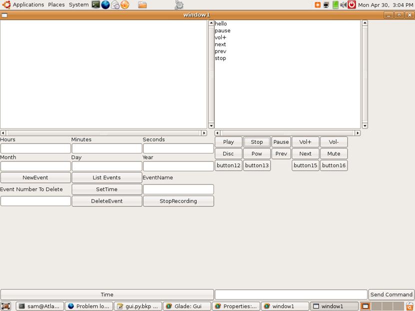
Figure 9 - GUI for More User Friendly Interface
6.3. Interference
It is possible for misuse of the device to generate large quantities of IR emmisions. This could result in jamming other nearby IR controlled devices.
7. Conclusion
7.1. Analysis
We successfully fulfilled the majority of the requirements that we specified. The device allows users to control an IR device (DVD player) based off of serial commands. It also allows the user to prerecord a set of actions to be executed at a specific time. All data that needs to be preserved is stored in the nonvolatile EEPORM, or in the nonvolatile memory within the realtime clock. The device is able to maintain time when power is disconnected via the RTC and backup battery.
7.2. Conformance to Standards
The standards on which the device relies are mostly de facto standards (SPI, I2C, IR codes). As such, we judge our conformance to them by the fact that all connected devices interface correctly.
7.3. Intellectual Property Considerations
Some of the codes used in the project are based on other sources, as listed below:
· We reused the code from Lab 3: Security Systems for the serial communication.
· The Two Wire Interface sending / receiving methods are based on the sample code in Mega32 Datasheet.
· The Serial Peripheral sending / receiving methods are based on the example given in the ECE 476 website.
In order to discover the exact protocal, carrier frequency and timing used by the specific dvd player we are controlling we measured the output from both our IR receiver and an infrared photodiode using an oscilloscope. The IR receiver showed us the proper pulse widths and timing parameters, while the photodiode also allowed us to measure the carrier frequency.
We did not have to sign a non-disclosure to get any sample part.
7.4. Ethical Considerations
In completing this project we made sure to avoid anything which might result in a safety hazard. We made sure that the output power of the LED was less than the level considered to be dangerous for human exposure. We had no conflicts of interests and did not accept bribes. We sought to make our expectations reasonable, and based off of our final results appear to have been successful with our estimates. In discussing what the capabilities of our device are in this document, we have been careful not to mislead or pad them. By documenting our work, we hope to expand the understanding of technology, particularly as it applies to our project. In designing and building our project, we increased our technical knowledge through experience. Both by what worked and what did not work, we learned (or relearned) techniques and skills necessary for designing systems. Throughout our writeup, we have done our best to make sure that we acknowledge the information and examples that we received from others, including from the internet. We did not injure anyone or cause any forms of harm during the design and construction of this project. We followed proper safety procedure while soldering the infrared receiver and while testing. By providing this report, we hope to assist others in their developement.
8. Appendix
8.1. Code Listing
8.1.1. prototypes.h
#include
<Mega32.h>
//
Bit patterns for sending instructions
//
Time definitions for timing various state machines
#define
HEADER_TIME 90 // Header time in
20us
#define
XMIT_TIME 1 // Transmit time in 20us
#define
RUN_TIME 15000 // Running state machine time in 20us
#define
RECV_TIME 15 // Receive time in 20us
#define
PULSE_TIME 50000 // Pulse time in 20us
#define
XMIT_BUFFER_SIZE 16 // Size of the IR transmit buffer
//
*********
//
Timing used to define the state of the IR Input Signal
#define
HEADER_MIN 750 // Header minimum time
#define
HEADER_MAX 1500 // Header maximum time
#define
LONG_MIN 325 //
Long signal minimum time
#define
LONG_MAX 562 // Long signal maximum time
#define
SHORT_MIN 100 // Short signal minimum time
#define
SHORT_MAX 200 // Short signal maximum time
//
Minimum allowable pulse. Used for filtering jitters
#define
LOW_MIN 100
//**********
#define
EVENT_CHIP 0x0e // Chip address for event chip
#define
MAX_EVENT_LENGTH 10 // Maximum number of
recordable
// events
#define
NUM_BLOCKS 2048 // Number of chunks
in the eeprom
//
Code to indicate current event chunk is valid
#define
VALID_EVENT 0x01
//
Code to indicate current event chunk is invalid
#define
INVALID_EVENT 0x00
//
Definitions to make Bruce Land's code work
#define
begin {
#define
end }
//
*****
// IR
Methods
void
ir_init(void); // Initialize
void
ir_xmitSM(void); // Transmit state
machine
void
ir_xmit(int data); // Put data into
the transmit buffer
char
ir_buffEmpty(void); // Is the transmit
buffer empty?
unsigned
int ir_data(void); // Get the received IR signal in hex form
//
*****
//
Parser Methods
void
par_init(void); // Initialize
parser
void
parser_SM(void); // Parser state
machine
void
parser_sendCommand(int cmd); // Send command to be transmitted
// or recorded
char
par_isRecording(void); // Is it in recording mode?
//
*****
//
Event Runner Methods
void
runner_init(void); // Initialize
void
runner_SM(void); // Event runner's
state machine
//
*****
//
EEPROM Methods
//
Write a byte to the EEPROM
void
ee_writeByte(char data, unsigned int addr, char chip_addr);
//
Read a byte of data from EEPROM
char
ee_readByte(unsigned int addr, char chip_addr);
//
*****
//
Serial methods
void
serial_init(void); // Initialize
void
sendStr (char * str); // Send string to
hyperterminal
char*
getStr(void); // Get string to
hyperterminal
char
ready_tx (void); // Is it ready to
transfer more strings?
//
*****
//
Clock methods
void
clk_init(void); // Initialize
//
Check if current time has passed the specified time
char
clk_passed(char sec, char min, char hr, char day, char mon, char yr);
//
Set the time of the real time clock
void
clk_setTime(char sec, char min, char hr, char day, char mon, char yr);
char
clk_sec(void); // Get the second
from real time clock
char
clk_min(void); // Get the minute
from real time clock
char
clk_hr(void); // Get the hour
from real time clock
char
clk_date(void); // Get the date
from real time clock
char
clk_mon(void); // Get the month
from real time clock
char
clk_yr(void); // Get the year
from real time clock
//
*****
//
TWI Methods
void
twi_init(void); // Initialize
void
twi_start(void); // Send start
signal
void
twi_stop(void); // Send stop
signal
void
twi_sendByte(char c); // Send the data
//
*****
//
SPI Methods
void
spi_init(void); // Initialize
void
spi_xmit(int cData); // Transmit data
char
spi_read(char addr); // Read data
//
EEPROM Debug Methods
//
Clear eeprom values between specified addresses
void
clear_eeprom(unsigned int fr, unsigned int to);
//
Printout eeprom values between specified addresses
void
read_eeprom(unsigned int fr, unsigned int to);
8.1.2. final.c
#include
"prototypes.h"
#include
<delay.h>
#include
<stdio.h>
#include
<string.h>
extern
char xmit_time; // xmit state machine
timer
unsigned
int run_time; // runner state machine
timer
//
flag to indicate if an IR signal is at the high state for
//
too long
extern
char invalid_fl;
//
The main initialize method
void
initialize(void);
//
Buffer containing times that the IR Signal is at high
extern
unsigned int time_buffer[128];
extern
char tb_ind; // Index of the time
buffer
long
count; // Used to count for
one second
//
Interrupt to drive state machine times
interrupt
[TIM0_COMP] void timer0_compare(void)
{
xmit_time++;
run_time++;
count++;
}
//
Interrupt used to signal if an IR signal is at a high
//
state for too long
interrupt
[TIM1_OVF] void timer1_overflow(void)
{
invalid_fl = 1;
}
//
DEBUG Method: Clear eeprom values between specified addresses
void
clear_eeprom(unsigned int fr, unsigned int to)
{
int addr;
PORTA.0 = ~PORTA.0;
for (addr = fr; addr < to; addr++)
{
ee_writeByte(0, addr, 0x0e);
delay_ms(5);
}
ee_writeByte(0, addr, 0x0e);
delay_ms(5);
PORTA.0 = ~PORTA.0;
}
//
DEBUG Method: Printout eeprom values between specified addresses
void
read_eeprom(unsigned int fr, unsigned int to)
{
int addr;
char buff[32];
char readVal;
PORTA.1 = ~PORTA.1;
addr = fr;
while (addr < to)
{
if(ready_tx())
{
readVal = ee_readByte(addr, 0x0e);
sprintf(buff, "%x: %x\n\r",
addr, readVal);
sendStr(buff);
addr++;
delay_ms(100);
}
}
while(!ready_tx()){}
readVal = ee_readByte(addr, 0x0e);
sprintf(buff, "%x: %x\n\r", addr,
readVal);
sendStr(buff);
addr++;
PORTA.1 = ~PORTA.1;
}
void
main(void)
{
initialize();
while(1)
{
unsigned int temp;
if (count > PULSE_TIME)
{
PORTA.7 = ~PORTA.7; // Heart beat
LED
count=0;
}
if(run_time == RUN_TIME)
{
runner_SM();
}
if(xmit_time == XMIT_TIME)
{
xmit_time = 0;
ir_xmitSM();
parser_SM();
}
// Check if any IR is received
temp= ir_data();
// Only record when in recording mode
if (temp != 0 &&
par_isRecording())
{
char t_buff[32];
// Print out the code to
Hyperterminal to let the
// user know that a code has been received
while(!ready_tx()){}
sprintf(t_buff, "CODE= %x ;
\n\r> ", temp);
sendStr (t_buff);
// If valid code
if((temp != 1) && (temp !=
2) && (temp != 3))
parser_sendCommand(temp);
}
}
}
void
test_init(void);
void
initialize(void)
{
char c[16];
sprintf(c, "Ready\n\r");
OCR0 =40; // 20 us
TIMSK=2; // turn on timer 0 cmp-match
ISR
TCCR0=0b00001010; // Clear on match, prescaler of 8
TIMSK = TIMSK | (0x04); // Turn on timer 1
overflow interrupt
TCCR1B = 0b00000011;
// TODO: Remove
DDRD.1 = 1;
DDRC.3 = 1;
DDRB.2 = 0;
DDRA = 0xff;
PORTA = 0xff;
// Initialize all the other initialize
methods
serial_init();
ir_init();
twi_init();
carrier_init();
par_init();
spi_init();
clk_init(); // ! Make sure that this comes AFTER
spi_init();
#asm
sei
#endasm
// Send message to hyperterminal
if(ready_tx())
sendStr(c);
}
8.1.3. serial.c
#include
<Mega32.h>
#include
"prototypes.h"
void
puts_int(void);
void
gets_int(void);
//RXC
ISR variables
unsigned
char r_index; //current string index
unsigned
char r_buffer[32]; //input string
unsigned
char r_ready; //flag for receive
done
unsigned
char r_char; //current character
//TX
empth ISR variables
unsigned
char t_index; //current string index
unsigned
char t_buffer[32]; //output string
unsigned
char t_ready; //flag for transmit
done
unsigned
char t_char; //current character
interrupt
[USART_RXC] void uart_rec(void)
begin
r_char=UDR; //get a char
UDR=r_char; //then print it
//build the input string
if (r_char != '\r')
r_buffer[r_index++]=r_char;
else
begin
putchar('\n'); //use putchar to avoid overwrite
r_buffer[r_index]=0x00; //zero terminate
r_ready=1; //signal cmd processor
UCSRB.7=0; //stop rec ISR
end
end
/**********************************************************/
//UART
xmit-empty ISR
interrupt
[USART_DRE] void uart_send(void)
begin
t_char = t_buffer[++t_index];
if (t_char == 0)
begin
UCSRB.5=0; //kill isr
t_ready=1; //transmit done
end
else {UDR
= t_char ; //send the char
}
end
void
puts_int(void){
t_ready=0;
t_index=0;
if (t_buffer[0]>0)
begin
putchar(t_buffer[0]);
UCSRB.5=1;
end
}
void
gets_int(void) {
r_ready=0;
r_index=0;
UCSRB.7=1;
}
void
sendStr (char * str)
begin
int i = 0;
for(i = 0; i < 32; i++)
begin
if(str[i] == 0) {
t_buffer[i]=0;
break;
}
t_buffer[i] = str[i];
end
puts_int();
end
char
* getStr ( void )
begin
char tempBuff[32];
if ( r_ready )
begin
sprintf( tempBuff, "%s",
r_buffer);
gets_int();
return r_buffer;
end
else
begin
return 0;
end
end
void
serial_init(void){
UCSRB = 0x18;
UBRRL = 103 ; //using a 16 MHz crystal
(9600 baud)
r_ready=0;
t_ready=1;
gets_int();
}
char
ready_tx (void){
return t_ready;
}
8.1.4. parser.c
#include
"prototypes.h"
#include
"codes.h"
//
Maximum number of characters for a command
#define
MAX_EVENT_NAME 5
//
Inherited from serial.c. Indicates if serial communication is ready
//
for more transmission
extern
char t_ready;
//******
//
List of command strings
//
Commands for the DVD Player
char
LIST_COMM[] = "h"; // List available commands and the
// formats
char
VOL_UP[] = "vol+"; // Increment volume by one
char
VOL_DOWN[] = "vol-"; // Decrement volume by one
char
POWER[] = "pow"; // Toggle power
char
MUTE[] = "mute"; // Toggle mute
char
PLAY[] = "play"; // Play
char
STOP[] = "stop"; // Stop
char
PAUSE[] = "pause"; // Pause / Resume
char
PREV[] = "prev"; // Previous
char
NEXT[] = "next"; // Next
char
DISC[] = "disc"; // Open / Close disc drive
//
Commands for the real time clock
char
SYNC[] = "sync "; // Sync the realtime clock
char
TIME[] = "time"; // Display the machine time
//
Event related commands
char
EVENT_NEW[] = "evnew"; // Create new event
char
EVENT_DEL[] = "evdel"; // Delete event
char
EVENT_LIST[] = "evls"; // List all events in eeprom
char
EVENT_FIN[] = "evfin"; // Finish recording event
//
Debugging commands to examine EEPROM
char
EE_CLR[] = "eeclr"; // DEBUG: Clear eeprom
char
EE_READ[] = "eesee"; // DEBUG: Print out eeprom
//
List of commands and the format
#define
NUM_CMDS 20
char
* commands[]=
{
"CONTROLS:\n\r"
"vol+\n\r",
"vol-\n\r",
"pow\n\r",
"mute\n\r",
"play\n\r",
"stop\n\r",
"pause\n\r",
"prev\n\r",
"next\n\r",
"disc\n\r",
"\n\rEVENTS\n\r",
"evnew <time>
<name>\n\r",
"evdel <addr>\n\r",
"evfin\n\r",
"evls\n\r",
"\n\rMISC\n\r",
"sync <time>\n\r",
"time\n\r",
"h\n\r"
};
//
Execute the command
void
exec(char* inst);
//
Save the event
void
saveEvent(void);
char
record_fl; // Flag to indicate if in
event recording mode
char
prompt_fl; // Flag to indicate if the
'>' character
// needs to be printed
//
Parameters used to create the event
char
ev_sec, ev_min, ev_hr, ev_day, ev_mon, ev_yr;
// Time parameters
char
ev_name[MAX_EVENT_NAME];
// Event name
//
Sequence of button presses for the event
unsigned
int ev_inst[MAX_EVENT_LENGTH];
char
ev_inst_ind; // Index for the list of
button presses
//
time parameters used to set the clock's time
char
s_sec, s_min, s_hr, s_day, s_mon, s_yr;
enum
parser_states { p_wait, p_parse, p_help, p_evlist, p_save, p_time,
p_rem_cpre, p_rem_cpwr, p_rem_del,
p_rem_print,
p_sendDelay, p_sync } parse_state, togo_state;
char
* buff; // Buffer for the command
received
char
line_cnt; // Number of lines
printed. Used for printing
// outputs with multiple
lines
char
delay_time; // Counter for delays
char
save_ind; // Index of instruction to
be saved
char
save_lower_fl; // Save the lower half of instruction?
//
Flag to indicate if "EVENTS:" has been printed out. Used when
//
Listing events stored in EEPROM
char
evlist_title_fl;
unsigned
int curr_ev_addr; // Current event
address
unsigned
int ev_addr; // Address of first
available space in EEPROM
unsigned
int rem_addr; // Address of event to
be removed
char
cp_ind; // Index of
instruction to be copied
unsigned
int cp_data; // Copied instruction
// Parser
state machine
void
parser_SM (void)
{
switch(parse_state)
{
case p_wait:
{
// Check if the prompt character
needs to be printed out
// and the serial communication is
ready to transmit
// more data
if(prompt_fl && t_ready)
{
char prbuff[5];
sprintf(prbuff, "\n\r>
");
sendStr(prbuff);
prompt_fl = 0;
}
buff = getStr();
// Check if there is new command from the
user
if(buff != 0)
{
prompt_fl = 1;
parse_state = p_parse;
}
}
break;
case p_parse:
// Execute the command
exec(buff);
break;
case p_help:
// Print out the list of commands
and the formats whenever
// the serial communication is
ready to transmit more
// data
if(t_ready)
{
sendStr(commands[line_cnt]);
line_cnt++;
if(line_cnt == NUM_CMDS - 1)
{
parse_state = p_wait;
}
}
break;
case p_evlist:
// Print out saved events
// Check if the "EVENTS:"
has been printed out
if(evlist_title_fl != 0)
{
if(ready_tx())
{
char buff[32];
sprintf(buff,
"EVENTS:\n\r");
sendStr(buff);
evlist_title_fl = 0;
}
}
else if(curr_ev_addr == ev_addr)
{
// all events have been printed
parse_state = p_wait;
}
else if(ready_tx())
{
// If serial communication is
ready for more transmission,
// printout next event
char data;
data = ee_readByte(curr_ev_addr
* 32, EVENT_CHIP);
if(data != INVALID_EVENT)
{
char name[MAX_EVENT_NAME +
1];
char buff[32];
char i;
// Read the name
for(i = 0; i < MAX_EVENT_NAME;
i++)
{
name[i] =
ee_readByte(curr_ev_addr * 32 + i + 1,
EVENT_CHIP);
}
name[MAX_EVENT_NAME] = 0;
sprintf(buff, "%x:
%s\n\r", curr_ev_addr, name);
sendStr(buff);
// Print out the next event
curr_ev_addr++;
}
}
break;
case p_save:
{
// Save the event to EEPROM
saveEvent();
}
break;
case p_time:
// If the IR transmit buffer is
empty and the serial
// communication is ready to
transmit more data, read the time
// from the real time clock and
print it out
if(ready_tx() &&
ir_buffEmpty())
{
char sc, mi, hr, dt, mo, yr;
char buff[32];
sc = clk_sec();
mi = clk_min();
hr = clk_hr();
dt = clk_date();
mo = clk_mon();
yr = clk_yr();
sprintf(buff,
"TIME:\n\r%d:%d:%d %d/%d/%d\n\r",
hr, mi, sc, dt, mo, yr);
sendStr(buff);
parse_state = p_wait;
}
break;
case p_rem_cpre:
{
// Work with cpwr to copy the event
at the end of the list
// to the removed position
// Read the instruction that the
specified position
if((ev_addr + 1) != rem_addr
&& cp_ind < 32)
{
cp_data = ee_readByte(ev_addr *
32 + cp_ind, EVENT_CHIP);
togo_state = p_rem_cpwr;
parse_state = p_sendDelay;
}
else
{
parse_state = p_rem_del;
}
}
break;
case p_rem_cpwr:
{
// Write the copied instructions to
a specified position
ee_writeByte(cp_data, rem_addr * 32
+ cp_ind, EVENT_CHIP);
cp_ind++;
togo_state = p_rem_cpre;
parse_state = p_sendDelay;
}
break;
case p_rem_del:
// Delete the last event in the
EEPROM
ee_writeByte(INVALID_EVENT,
ev_addr*32, EVENT_CHIP);
togo_state = p_rem_print;
parse_state = p_sendDelay;
break;
case p_rem_print:
// Print out the event number that
has been removed
if(ready_tx())
{
char buff[32];
sprintf(buff, "Event %x
Removed\n\r", rem_addr);
sendStr(buff);
parse_state = p_wait;
}
break;
case p_sendDelay:
// Provides 5 ms delay. Used to
make sure that eeprom
// write and read have been
completed before attempting
// another write / read.
if (delay_time == 250)
{
parse_state = togo_state;
}
else
{
delay_time++;
}
break;
case p_sync:
// Set the time of the real time
clock. Do this only when
// the transmit buffer is empty.
if(ir_buffEmpty() &&
ready_tx())
{
char buff[32];
clk_setTime(s_sec, s_min, s_hr,
s_day, s_mon, s_yr);
sprintf(buff, "Clock
set\n\r");
sendStr(buff);
parse_state = p_wait;
}
break;
}
}
//
Send the command either to IR LED or to be saved as an
//
event instruction
void
parser_sendCommand(int cmd)
{
if(record_fl)
{
ev_inst[ev_inst_ind] = cmd;
ev_inst_ind++;
}
else
{
ir_xmit(cmd);
}
}
//
Parse and executes the instruction
void
exec(char* inst)
{
// List all commands
if(strcmp(inst, LIST_COMM) == 0)
{
line_cnt = 0;
parse_state = p_help;
}
// Increment volume
else if (strcmp(inst, VOL_UP) == 0)
{
parser_sendCommand(VOLUME_PLUS_CODE);
parse_state = p_wait;
}
// Decrement Volume
else if (strcmp(inst, VOL_DOWN) == 0)
{
parser_sendCommand(VOLUME_MINUS_CODE);
parse_state = p_wait;
}
// Toggle Power
else if (strcmp(inst, POWER) == 0)
{
parser_sendCommand(STANDBY_CODE);
parse_state = p_wait;
}
// Toggle Mute
else if (strcmp(inst, MUTE) == 0)
{
parser_sendCommand(MUTE_CODE);
parse_state = p_wait;
}
// Play
else if (strcmp(inst, PLAY) == 0)
{
parser_sendCommand(PLAY_CODE);
parse_state = p_wait;
}
// Stop
else if (strcmp(inst, STOP) == 0)
{
parser_sendCommand(STOP_CODE);
parse_state = p_wait;
}
// Pause / Skip
else if (strcmp(inst, PAUSE) == 0)
{
parser_sendCommand(PAUSE_STEP_CODE);
parse_state = p_wait;
}
// Previous
else if (strcmp(inst, PREV) == 0)
{
parser_sendCommand(PREV_CODE);
parse_state = p_wait;
}
// Next
else if (strcmp(inst, NEXT) == 0)
{
parser_sendCommand(NEXT_CODE);
parse_state = p_wait;
}
// Open / Close disc
else if (strcmp(inst, DISC) == 0)
{
parser_sendCommand(OPEN_CLOSE_CODE);
parse_state = p_wait;
}
// List Stored Events
else if (strcmp(inst, EVENT_LIST) == 0)
{
curr_ev_addr = 0;
evlist_title_fl = 1;
parse_state = p_evlist;
}
// Stop recording event
else if (strcmp(inst, EVENT_FIN) == 0)
{
record_fl = 0;
save_ind = 0;
save_lower_fl = 0;
parse_state = p_save;
}
// System time
else if (strcmp(inst, TIME) == 0)
{
parse_state = p_time;
}
// Instructions with input parameters
else
{
// Now parse commands with input
parameter(s)
char tstr[6];
// temporary buffer for section of the
input command that will
// not be used
char junk[16];
// Get the first 5 characters and
terminate them with null terminator
tstr[0] = inst[0];
tstr[1] = inst[1];
tstr[2] = inst[2];
tstr[3] = inst[3];
tstr[4] = inst[4];
tstr[5] = 0;
// Check what the first 5 characters of
the command are
// Set the time
if(strcmp(tstr, SYNC) == 0)
{
sscanf(inst, "%s %d %d %d %d
%d %d", junk,
&s_sec, &s_min,
&s_hr, &s_day, &s_mon, &s_yr);
parse_state = p_sync;
}
// Create new event
else if (strcmp(tstr, EVENT_NEW) == 0)
{
char buff[32];
char i;
if(record_fl == 0)
{
// Get the times for the event
sscanf(inst, "%s %d %d %d
%d %d %d %s", junk,
&ev_sec, &ev_min,
&ev_hr, &ev_day, &ev_mon, &ev_yr,
ev_name);
ev_inst_ind = 0; // Initialize the event list index
// Empty the event list
for(i = 0; i <
MAX_EVENT_LENGTH; i++)
{
ev_inst[i] = 0;
}
record_fl = 1; // Start recording
// Print out friendly message
to user
sprintf(buff, "RECORDING
%s\n\r", ev_name);
// Wait until serial xmit is
ready
while(!t_ready){}
sendStr(buff);
parse_state = p_wait;
}
else
{
// Cannot create new event in
recording mode
}
}
// Delete event
else if (strcmp(tstr, EVENT_DEL) == 0)
{
unsigned int addr;
sscanf(inst, "%s %x",
junk, &addr);
rem_addr = addr;
if(ev_addr != rem_addr)
ev_addr--;
cp_ind = 0;
parse_state = p_rem_cpre;
}
// Clear eeprom
else if (strcmp(tstr, EE_CLR) == 0)
{
unsigned int fr, to;
sscanf(inst, "%s %x %x",
junk, &fr, &to);
clear_eeprom(fr, to);
parse_state = p_wait;
}
// Read eeprom
else if (strcmp(tstr, EE_READ) == 0)
{
unsigned int fr, to;
sscanf(inst, "%s %x %x",
junk, &fr, &to);
read_eeprom(fr, to);
parse_state = p_wait;
}
else
{
sprintf(buff, "Invalid input
%s\n\r", tstr);
// Wait until serial xmit is ready
while(!t_ready){}
parse_state = p_wait;
}
}
}
//
Save the event to eeprom
void
saveEvent(void)
{
char buff[32];
// Event storage format:
// 0
: ValidEvent
// 1-5
: 10 chars name
// 6
: Seconds
// 7
: Minutes
// 8
: Hours
// 9
: Day
// 10
: Month
// 11
: Year
// 12-31: Code 1-10
// Check if the transmit buffer is empty
if(ir_buffEmpty())
{
// Save the "valid" header
if(save_ind == 0)
{
ee_writeByte(VALID_EVENT
,ev_addr*32 + save_ind, EVENT_CHIP);
save_ind++;
delay_time = 0;
togo_state = p_save;
parse_state = p_sendDelay;
}
// Save the name of the event
else if (1 <= save_ind &&
save_ind <= 5)
{
ee_writeByte(ev_name[save_ind - 1],
ev_addr * 32 + save_ind,
EVENT_CHIP);
save_ind++;
delay_time = 0;
togo_state = p_save;
parse_state = p_sendDelay;
}
// Save the second
else if (save_ind == 6)
{
ee_writeByte(ev_sec ,ev_addr * 32 +
save_ind, EVENT_CHIP);
save_ind++;
delay_time = 0;
togo_state = p_save;
parse_state = p_sendDelay;
}
// Save the minute
else if (save_ind == 7)
{
ee_writeByte(ev_min ,ev_addr * 32 +
save_ind, EVENT_CHIP);
save_ind++;
delay_time = 0;
togo_state = p_save;
parse_state = p_sendDelay;
}
// Save the hours
else if (save_ind == 8)
{
ee_writeByte(ev_hr ,ev_addr * 32 +
save_ind, EVENT_CHIP);
save_ind++;
delay_time = 0;
togo_state = p_save;
parse_state = p_sendDelay;
}
// Save the date
else if (save_ind == 9)
{
ee_writeByte(ev_day ,ev_addr * 32 +
save_ind, EVENT_CHIP);
save_ind++;
delay_time = 0;
togo_state = p_save;
parse_state = p_sendDelay;
}
// Save the month
else if (save_ind == 10)
{
ee_writeByte(ev_mon ,ev_addr * 32 +
save_ind, EVENT_CHIP);
save_ind++;
delay_time = 0;
togo_state = p_save;
parse_state = p_sendDelay;
}
// Save the year
else if (save_ind == 11)
{
ee_writeByte(ev_yr ,ev_addr * 32 +
save_ind, EVENT_CHIP);
save_ind++;
delay_time = 0;
togo_state = p_save;
parse_state = p_sendDelay;
}
// Save the sequence of button press
else if (12 <= save_ind &&
save_ind < 32)
{
if(save_lower_fl)
{
// Save the lower half
ee_writeByte( ((char)
ev_inst[(save_ind - 13) / 2])
, ev_addr * 32 + save_ind,
EVENT_CHIP);
save_lower_fl = 0;
delay_time = 0;
togo_state = p_save;
parse_state = p_sendDelay;
}
else
{
// Save the upper half
ee_writeByte(
(ev_inst[(save_ind - 12) / 2] >> 8), ev_addr *
32 + save_ind, EVENT_CHIP);
save_lower_fl = 1;
delay_time = 0;
togo_state = p_save;
parse_state = p_sendDelay;
}
save_ind++;
}
else
{
// Finished saving?
ev_addr++;
while(!t_ready){}
sprintf(buff, "DONE
RECORDING\n\r");
sendStr(buff);
parse_state = p_wait;
}
}
}
//
Go through the EEPROM, and find the location of the
//
first invalid event. This is called only during
//
initialization, used to minimize EEPROM search time
void
findFirstInvalidEvent(){
unsigned int addr=0;
while (1)
{
char c;
c= ee_readByte(addr*32, EVENT_CHIP);
if (c!=VALID_EVENT)
{
ev_addr=addr;
break;
}
else
{
addr++;
if (addr >= NUM_BLOCKS)
{
ev_addr= addr;
break;
}
}
}
}
//
Is it in recording state?
char
par_isRecording(void)
{
return record_fl;
}
//
Initialize the parser
void
par_init(void)
{
parse_state = p_wait;
prompt_fl = 1;
findFirstInvalidEvent();
}
8.1.5. spi.c
#include
"prototypes.h"
#include
<spi.h>
#include
<delay.h>
//
Bit numbers for setting the registry
#define
DD_MOSI 5
#define
DD_MISO 6
#define
DD_SCK 7
#define
SPE 6
#define
MSTR 4
#define
SPR0 0
#define
SPIF 7
#define
DDR_SPI DDRB
//
Used for debugging
#define
SPI_EN 1
//
Transmit 16 bit data to the real time clock using SPI interface
void
spi_xmit(int cData)
{
#if SPI_EN
unsigned char junk;
PORTB.2 = 1; // Turn cm to high
junk = spi(cData >> 8); // Send the top 8 bits
junk = spi(cData & 0xff) ; // Send the bottom 8 bits
PORTB.2 = 0; // Turn cm to low
#endif
}
//
Transmit 8 bit data, and return the returned data
unsigned
char spi_read(char addr)
{
#if SPI_EN
unsigned char junk, Ain;
PORTB.2 = 1; // Turn cm to high
junk = spi(addr); // Send the address
Ain = spi(0x00); // Read the value
PORTB.2 = 0; // Turn cm to low
#endif
return Ain;
}
//
Initialization method
void
spi_init(void)
{
#if SPI_EN
//set up SPI
//bit 7 SPIE=0 no ISR
//bit 6 SPE=1 enable spi
//bit 5 DORD=0 msb first
//bit 4 MSTR=1 Mega32 is spi master
//bit 3 CPLO=1 clock polarity
//bit 2 CPHA=1 clock phase
//bit 1,0 rate sel=10 along with SPRC=1
sets clk to f/32 = 500 kHz
SPCR = 0b01011111 ;
SPSR = 1;
//set up i/o data direction
DDRB.2 = 1;
DDRB.4 = 1;
DDRB.5 = 1; //output MOSI
DDRB.6 = 0; //input MISO
DDRB.7 = 1; //output SCLK
#endif
}
8.1.6. clk.c
#include
"prototypes.h"
#define
SEC_READ 0x00
#define
SEC_WRITE 0x80
#define
MIN_READ 0x01
#define
MIN_WRITE 0x81
#define
HR_READ 0x02
#define
HR_WRITE 0x82
#define
DAT_READ 0x04
#define
DAT_WRITE 0x84
#define
MON_READ 0x05
#define
MON_WRITE 0x85
#define
YR_READ 0x06
#define
YR_WRITE 0x86
//
Get the real second
char
clk_sec(void)
{
char s, tens, ones;
s = spi_read(SEC_READ);
tens = (s >> 4) & 0x07;
ones = s & 0x0f;
return tens * 10 + ones;
}
//
Get the real minute
char
clk_min(void)
{
char m, tens, ones;
m = spi_read(MIN_READ);
tens = (m >> 4) & 0x07;
ones = m & 0x0f;
return tens * 10 + ones;
}
//
Get the real hour
char
clk_hr(void)
{
char hr, tens, ones;
hr = spi_read(HR_READ);
tens = (hr >> 4) & 0x03;
ones = hr & 0x0f;
return tens * 10 + ones;
}
//
Get the real date
char
clk_date(void)
{
char d, tens, ones;
d = spi_read(DAT_READ);
tens = (d >> 4) & 0x03;
ones = d & 0x0f;
return tens * 10 + ones;
}
//
Get the real month
char
clk_mon(void)
{
char m, tens, ones;
m = spi_read(MON_READ);
tens = (m >> 4) & 0x03;
ones = m & 0x0f;
return tens * 10 + ones;
}
//
Get the real year
char
clk_yr(void)
{
char y, tens, ones;
y = spi_read(YR_READ);
tens = (y >> 4) & 0x0f;
ones = y & 0x0f;
return tens * 10 + ones;
}
//
Convert a normal number to the number format used
//
by the real time clock, with top 4 bits representing
//
tens, and lower 4 bits ones
char
ToTensOnes(unsigned char n)
{
return ((n / 10) << 4) + (n % 10);
}
//
Set the time of the real time clock
void
clk_setTime(char sec, char min, char hr, char day, char mon, char yr)
{
unsigned int temp;
// Set the year
spi_xmit((((unsigned int) YR_WRITE)
<< 8) + ToTensOnes(yr));
spi_xmit((((unsigned int) MON_WRITE)
<< 8) + ToTensOnes(mon));
spi_xmit((((unsigned int) DAT_WRITE)
<< 8) + ToTensOnes(day));
// Set the hour
temp = ((unsigned int) HR_WRITE) <<
8;
temp += (0 << 6);
temp += ToTensOnes(hr) & 0x3f;
spi_xmit(temp);
spi_xmit((((unsigned int) MIN_WRITE)
<< 8) + ToTensOnes(min));
spi_xmit((((unsigned int) SEC_WRITE)
<< 8) + ToTensOnes(sec));
}
//
Check if current time has passed the specified time
char
clk_passed(char sec, char min, char hr, char day, char mon, char yr)
{
char ryr, rmon, rdat, rhr, rmin, rsec;
ryr = clk_yr();
rmon = clk_mon();
rdat = clk_date();
rhr = clk_hr();
rmin = clk_min();
rsec = clk_sec();
// Check the year
if(yr < ryr)
return 1;
else if( yr > ryr)
return 0;
// Check the month
if(mon < rmon)
return 1;
else if( mon > rmon)
return 0;
// Check the date
if(day < rdat)
return 1;
else if( day > rdat)
return 0;
// Check the hour
if(hr < rhr)
return 1;
else if( hr > rhr)
return 0;
// Check the minute
if(min < rmin)
return 1;
else if( min > rmin)
return 0;
// Check the second
if(sec <= rsec)
return 1;
else if( sec > rsec)
return 0;
}
//
Initialize
void
clk_init(void)
{
char hr;
// Initialize the registers of the clock
spi_xmit(0b1000111100000000);
// Set the hour mode to 24
hr = spi_read(HR_READ);
hr = hr & ~(1 << 6);
spi_xmit((((unsigned int ) HR_WRITE)
<< 8) + hr);
}
8.1.7. i2c.c
#include
"prototypes.h"
//
Define bit numbers for the registers
#define
TWINT 7
#define
START 5
#define
MT_SLA_ACK 0
#define
TWSTA 5
#define
TWEN 2
#define
TWSTO 4
#define
MAX_READ_SIZE 255
void
ERROR(void)
{
}
//
Enable ACK
void
twi_enable_ack(void)
{
TWCR|= 64;
}
//
Disable ACK
void
twi_disable_ack(void)
{
TWCR&=~(64);
}
//
Send the start signal
void
twi_start(void)
{
TWCR =
(1<<TWINT)|(1<<TWSTA)|(1<<TWEN);
while (!(TWCR & (1<<TWINT)));
if
((TWSR & 0xF8) != START)
ERROR();
}
//
Send the stop signal
void
twi_stop(void)
{
TWCR =
(1<<TWINT)|(1<<TWEN)|(1<<TWSTO);
}
//
Send a byte of character
void
twi_sendByte(char c)
{
TWDR = c;
TWCR = (1<<TWINT) | (1<<TWEN);
while (!(TWCR & (1<<TWINT)));
if ((TWSR & 0xF8) != MT_SLA_ACK)
ERROR();
}
//
Read a byte of character
char
twi_readByte(void)
{
TWCR = (1<<TWINT) | (1<<TWEN);
while (!(TWCR & (1<<TWINT)));
if ((TWSR & 0xF8) != MT_SLA_ACK)
ERROR(); // TODO: Change this
return TWDR;
}
//
Write a byte using EEPROM's scheme
void
ee_writeByte(char data, unsigned int addr, char chip_addr)
{
// Send the start signal
twi_start();
// Send the header and 16 bit address
twi_sendByte(0xa0 | (chip_addr &
0x0e));
twi_sendByte(addr >> 8);
twi_sendByte(addr & 0x00ff);
// Send the data
twi_sendByte(data);
// Send the stop signal
twi_stop();
}
//
Read a byte using EEPROM's scheme
char
ee_readByte(unsigned int addr, char chip_addr)
{
char data;
// Send the start signal
twi_start();
// Send the header and 16 bit address
twi_sendByte(0xa0 | (chip_addr &
0x0e));
twi_sendByte(addr >> 8);
twi_sendByte(addr & 0x00ff);
// Send another start signal
twi_start();
// Send address to read and disable ACK
twi_sendByte(0xa0 | (chip_addr & 0x0e)
| 1);
twi_disable_ack();
// Get the data
data = twi_readByte();
// Send the stop signal
twi_stop();
// Return the data obtained from EEPROM
return data;
}
//
Initialize
void
twi_init(void)
{
TWBR = 12;
TWSR &= ~3;
TWCR = 0b01000100;
}
8.1.8. ir.c
#include
"prototypes.h"
#include
<stdio.h>
#define
SYNC_PULSE 0x00ff;
//
Flag to indicate if the compare match interrupt
//
Should time the header
char
meas_fl;
//
Flag indicating that signal is invalid
char
invalid_fl;
char
header_time; // timed by the
compare match ISR
char
xmit_time; // xmit state machine
timer
//
Transmit buffer
int
xmit_buffer[XMIT_BUFFER_SIZE];
char
old_xmit_ind; // Old transmit index
char
xmit_ind; // Transmit index
//
Receive buffer
char
recv_ind; // Receive index
char
recv_done_fl; // Flag to indicate if an instruction has
been received
//
Buffer containing time lengths of high states
unsigned
int time_buffer[128];
char
tb_ind; // Index of the buffer
interrupt
[EXT_INT1] void ext_interrupt(void)
{
if(PIND.3 == 1)
{
TCNT1 = 0;
}
else
{
unsigned int time;
time = TCNT1;
if(!invalid_fl)
{
if (time>LOW_MIN){
time_buffer[tb_ind] = time;
tb_ind = (tb_ind + 1) % 128;
}
}
}
invalid_fl = 0;
}
//
Turn on the IR LED
void
ir_on(void)
{
//DDRD.7 = 1;
TCCR2 |=(1<<4);
PORTC.3= 1;
}
//
Turn off the IR LED
void
ir_off(void)
{
//DDRD.7 = 0;
TCCR2 &=~(1<<4);
PORTC.3= 0;
}
//
Send a 12 bit data through ir
void
ir_xmit(int data)
{
xmit_buffer[xmit_ind] = data;
xmit_ind = (xmit_ind + 1) %
XMIT_BUFFER_SIZE;
}
enum
xmit_states { x_wait, x_pull, x_header, x_high, x_lo2, x_lo, x_bit,
x_trigDlay, x_trigLo, x_trigHi, x_interDlay
} xmit_state;
char
xmit_c; // General counter
char
xmit_t, xmit_th; // Used for timing
//
Flag to indicate if the sync signal needs to be sent
char
sendSync_fl;
//
Flag to indicate if the trigger signal has been sent
char
trigDone_fl;
int
sentData;
//
The transmit state machine
void
ir_xmitSM(void)
{
switch(xmit_state)
{
// Wait until there is instruction to
be sent
case x_wait:
if(old_xmit_ind != xmit_ind)
{
char buff[32];
// Check if there is nothing to
send
if(xmit_buffer[old_xmit_ind] == 0)
{
old_xmit_ind =
(old_xmit_ind + 1) % XMIT_BUFFER_SIZE;
}
else
{
ir_on();
xmit_t = 0;
xmit_th = 0;
xmit_c = 0;
sendSync_fl = 1;
trigDone_fl = 0;
sentData = SYNC_PULSE;
xmit_state = x_pull;
}
}
else
{
}
break;
// Send the pull signal
case x_pull:
if(xmit_th == 2)
{
ir_off();
xmit_state = x_header;
xmit_t = 0;
xmit_th = 0;
}
else if(xmit_t == 230)
{
xmit_th++;
xmit_t = 0;
}
else
{
xmit_t++;
}
break;
// Send the header
case x_header:
if(xmit_t == 214) // Wait until header is 4.4 ms long
{
ir_on();
xmit_t = 0;
xmit_state = x_high;
}
else
{
xmit_t++;
}
break;
// Send a normal high signal
case x_high:
if(xmit_t == 31) // Wait until low for 600 us
{
if(trigDone_fl)
{
// Header, instruction, and
trigger have all been sent.
// Move to the next
instruction
ir_off();
xmit_t = 0;
xmit_th = 0;
xmit_state = x_interDlay;
}
else if(xmit_c == 16)
{
// The current 16 bits data
has been sent.
if(!sendSync_fl)
{
// Current instruction
has been sent.
// Now send the trigger
signal
ir_off();
xmit_t = 0;
xmit_th = 0;
xmit_state =
x_trigDlay;
}
else
{
// sync pulse has been
sent. Now send the data
sentData =
xmit_buffer[old_xmit_ind];
sendSync_fl = 0;
ir_off();
xmit_state = x_lo;
xmit_t = 0;
xmit_c = 0;
}
}
else
{
// Send the sync pulses
ir_off();
xmit_state = x_lo;
xmit_t = 0;
}
}
else
{
xmit_t++;
}
break;
// Send the first low signal for a 0 or
1 bit
case x_lo:
if(xmit_t == 23) // Wait until hi is 520 us long
{
xmit_state = x_bit;
xmit_t = 0;
}
else
{
xmit_t++;
}
break;
// Send the second hi signal for a 1 bit
case x_lo2:
if(xmit_t == 54)
{
ir_on();
xmit_t = 0;
xmit_state = x_high;
}
else
{
xmit_t++;
}
break;
// Check if the next bit is one
case x_bit:
{
int mask;
int b;
mask = 0x8000 >> xmit_c;
xmit_c++;
// Get the current bit
b = sentData & mask;
if(b == 0)
{
ir_on();
xmit_t = 0;
xmit_state = x_high;
}
else
{
xmit_t = 0;
xmit_state = x_lo2;
}
}
break;
// Gives a long hi delay for the
trigger signal
case x_trigDlay:
{
if(xmit_th == 15)
{
ir_on();
xmit_state = x_trigHi;
xmit_t = 0;
xmit_th = 0;
}
else if(xmit_t == 128)
{
xmit_th++;
xmit_t = 0;
}
else
{
xmit_t++;
}
}
break;
// Low trigger period before the
trigger high
case x_trigHi:
if(xmit_th == 3)
{
ir_off();
xmit_state = x_trigLo;
xmit_t = 0;
xmit_th = 0;
}
else if(xmit_t == 150)
{
xmit_th++;
xmit_t = 0;
}
else
{
xmit_t++;
}
break;
// High trigger period before the
trigger low
case x_trigLo:
if(xmit_t == 110)
{
ir_on();
trigDone_fl = 1;
xmit_t = 0;
xmit_state = x_high;
}
else
{
xmit_t++;
}
break;
case x_interDlay:
if(xmit_th == 100)
{
xmit_t = 0;
xmit_th = 0;
// Move to the next instruction
old_xmit_ind = (old_xmit_ind + 1) %
XMIT_BUFFER_SIZE;
xmit_state = x_wait;
}
else if(xmit_t == 255)
{
xmit_th++;
xmit_t = 0;
}
else
{
xmit_t++;
}
break;
}
}
//
Checks if the transmit buffer is empty
char
ir_buffEmpty(void)
{
return old_xmit_ind == xmit_ind;
}
//
Check if time is a header
unsigned
char isHeader(int time){
return (HEADER_MIN < time &&
time < HEADER_MAX);
}
//
Check if time is a long
unsigned
char isLong(int time){
return
(LONG_MIN < time && time < LONG_MAX);
}
//
Check if time is a short
unsigned
char isShort(int time){
return (SHORT_MIN < time && time
< SHORT_MAX);
}
//
Go through the time buffer and convert all times to binary format
//
and return it
unsigned
int ir_data(void){
unsigned int val=0;
if (invalid_fl){
if (tb_ind > 30){
// Check for header
if (!isHeader(time_buffer[0])){
tb_ind=0;
return 1;
}
// Check for 8 short signals
for (i=1;i<9;i++){
if (!isShort(time_buffer[i])){
tb_ind=0;
return 2; // bad start
}
}
// Check for 8 long signals
for (i=9;i<17;i++){
if (!isLong(time_buffer[i])){
tb_ind=0;
return 3; // bad start
}
}
// Convert the 16 bit instructions
to binary form
for (i = 17; i < 33;i++){
val= val | ( ( !!(unsigned
long)isLong(time_buffer[i]) << (32 - i)));
}
}
tb_ind=0;
}
return val;
}
//
Initialize
void
ir_init(void)
{
// Initialize the external interrupt
// Set to interrupt at any logical change
// For int1
MCUCR |=(1<<2);
MCUCR &=~(1<<3);
GICR |= 128; // Set bit 6 to 1, enable external
interrupt
meas_fl = 0;
xmit_t = 0;
xmit_c = 0;
recv_ind = 0;
recv_done_fl = 0;
// TODO: remove
time_buffer[0] = 0;
time_buffer[1] = 0;
fall_state = f_init;
rise_state = r_init;
recv_char = 0xffffffff;
//test
ir_off();
}
8.1.9. carrier.c
#include
"prototypes.h"
//
Sets Timer 2 to oscillate OCR2 at rate of around 38 kHz
void
carrier_init(void){
// set OCR2 to 199 for approx 40 khz
//OCR2=199;
// set OCR2 to 210 for approx 38 khz
OCR2=210;
//CTC, toggle, no prescaler
TCCR2= 0b00011001;
// Set D.7 to output, initialize to low
DDRD.7 =1;
PORTD.7=0;
}
8.1.10. runner.c
#include
"prototypes.h"
// Address
of the first invalid event block in EEPROM
//
Inherited from parser
extern
unsigned int ev_addr;
enum
runner_states { r_waitEvent, r_waitBuffer} runner_state;
unsigned
int check_ev_addr; // Address of event
to be checked
unsigned
int ran_ev_addr; // Address of event
to be run
char
r_inst_ind; // Index of the
instruction to be sent
// to the IR
Transmitter
//
Temporary time variables
char
sc, mn, hr, dy, mo, yr;
unsigned
int ev_data; // Data to be
transmitted
//
Periodically checks the events in the eeprom and
//
see if any of them needs to be run
void
runner_SM(void)
{
switch(runner_state)
{
case r_waitEvent:
{
// Wait until there are events in
the eeprom and the
// ir_xmit buffer is empty
if(check_ev_addr < ev_addr
&& ir_buffEmpty())
{
// Get the times of the events
sc = ee_readByte(check_ev_addr
* 32 + 6, EVENT_CHIP);
mn = ee_readByte(check_ev_addr * 32 + 7,
EVENT_CHIP);
hr = ee_readByte(check_ev_addr
* 32 + 8, EVENT_CHIP);
dy = ee_readByte(check_ev_addr
* 32 + 9, EVENT_CHIP);
mo = ee_readByte(check_ev_addr
* 32 + 10, EVENT_CHIP);
yr = ee_readByte(check_ev_addr
* 32 + 11, EVENT_CHIP);
// Check if it is time to run
the event
if(clk_passed(sc, mn, hr, dy,
mo, yr))
{
r_inst_ind = 0;
runner_state = r_waitBuffer;
ran_ev_addr =
check_ev_addr;
}
else
{
runner_state = r_waitEvent;
}
}
else if (! (check_ev_addr <
ev_addr))
{
check_ev_addr = 0;
}
else {
// do nothing
}
// Check the next event
check_ev_addr = (check_ev_addr + 1)
% ev_addr;
}
break;
case r_waitBuffer:
// Wait until the transmit buffer
is empty
if(ir_buffEmpty())
{
char i;
char tempData;
// Send each saved button press
to the ir transmit buffer
for(i = 0; i <
MAX_EVENT_LENGTH; i++)
{
ev_data = 0;
// Get the upper 8 bits
tempData = ee_readByte((unsigned
int)ran_ev_addr * 32 + 12 + (unsigned int)i * 2, EVENT_CHIP);
ev_data = ((unsigned int)
tempData) << 8;
// Get the lower 8 bits
tempData =
ee_readByte((unsigned int)ran_ev_addr * 32 + 13 + (unsigned int)i * 2,
EVENT_CHIP);
ev_data = ev_data |
tempData;
// Send the instruction
ir_xmit(ev_data);
}
// Delete the executed event
from the EEPROM
// Copy from the end of the
eeprom to the current location
if(ev_addr != ran_ev_addr)
{
char cp_ind = 0;
ev_addr--;
// Copy the last event to
the event in the deleted position
for(cp_ind = 0; cp_ind <
32; cp_ind++)
{
char cp_data;
cp_data =
ee_readByte(ev_addr * 32 + cp_ind, EVENT_CHIP);
delay_ms(5);
ee_writeByte(cp_data,
ran_ev_addr * 32 + cp_ind, EVENT_CHIP);
delay_ms(5);
}
}
ee_writeByte(INVALID_EVENT,
ev_addr * 32, EVENT_CHIP);
delay_ms(5);
// reset checked address to
zero.
check_ev_addr = 0;
runner_state = r_waitEvent;
}
break;
}
}
8.1.11. GUI Code
8.2. Schematics
8.3. Cost Details
|
Parts |
Cost |
|
STK500 |
$15 |
|
White Board |
$6 |
|
B / W TV |
$5 |
|
IR LED |
$3.29 |
|
|
$0.27 |
|
Backup |
$3.29 |
|
TOTAL |
$32.85 |
All other parts are either sampled free, or have been owned previously.
8.4. Tasks of Each Group Member
Hardware: Sam
Software
- EEPROM: Both
- Event
Runner:
- GUI: Sam
- IR Receiver: Both
- IR
Transmitter:
- Parser:
- Real
Time Clock:
- SPI: Both
- TWI: Both
Website / Writeup: Both
8.5. References
Serial
Communicator Base Code: http://instruct1.cit.cornell.edu/courses/ee476/Serialcom/SerialInt.c
SPI Scheme: http://instruct1.cit.cornell.edu/courses/ee476/SPI/index.html
SPI Standards: http://www.maxim-ic.com/appnotes.cfm/appnote_number/502
ATMega32
Datasheet: http://instruct1.cit.cornell.edu/courses/ee476/AtmelStuff/full32.pdf
AA1025 Datasheet: http://ww1.microchip.com/downloads/en/DeviceDoc/21941B.pdf
DS1305 Datasheet: http://datasheets.maxim-ic.com/en/ds/DS1305.pdf