Star Seeker
"Find It Now, Find It Fast"
ECE 476 Final Project
Ian Yik Oon Quek (iq23), Tze Wei Kevin Goh (tg67)
Contents
1
Introduction
Our project involves the construction of a telescope mount which automatically rotates a telescope to track a star selected by the user. This project intends to create an automatic application for users who wish to track stars without the hassle of adjusting the telescope themselves.
Users would be able to track a given list of stars, or input their own data for the telescope mount to track their own desired star. The project consist of two main components: the mechanical construction of the mount and the software required in accepting user input and operating the mount itself.

Figure 1.1.1: Our Project Group. Click to enlarge.
![]()
![]()
2
High Level Design
2.1
Rationale and Project Idea
We wanted out project to have a significant hardware and software component. By choosing to design and build a telescope mount, we were be able to accomplish this. The mount would require significant machining, along with the addition of electrical components such as a motor, pulleys, an LCD screen, a keypad and a Mega32 MCU, which would give us experience in hardware design. The software to accept user input, calculate local sidereal time (LST), find the coordinates of a given star, and operate the motor would do the same in software design.
We also deemed that the project would fit within the budget constraints. The mount was constructed out of scrap metal scavenged from the machine shop, while the pulleys, motor and screws were sampled and donated from companies like [Lin Engineering]. Most of the cost went towards using the LCD, keypad and Mega32 components.
The project was also motivated from Ian’s love of star/aurora-watching. The idea was further strengthened by a website by Jerry Oltion [link], which was our original challenge. However, his idea was too difficult to implement in the short period of time we were given and therefore we decided to simplify it. We also decided this would be an innovative use of scrap materials and some electrical components.
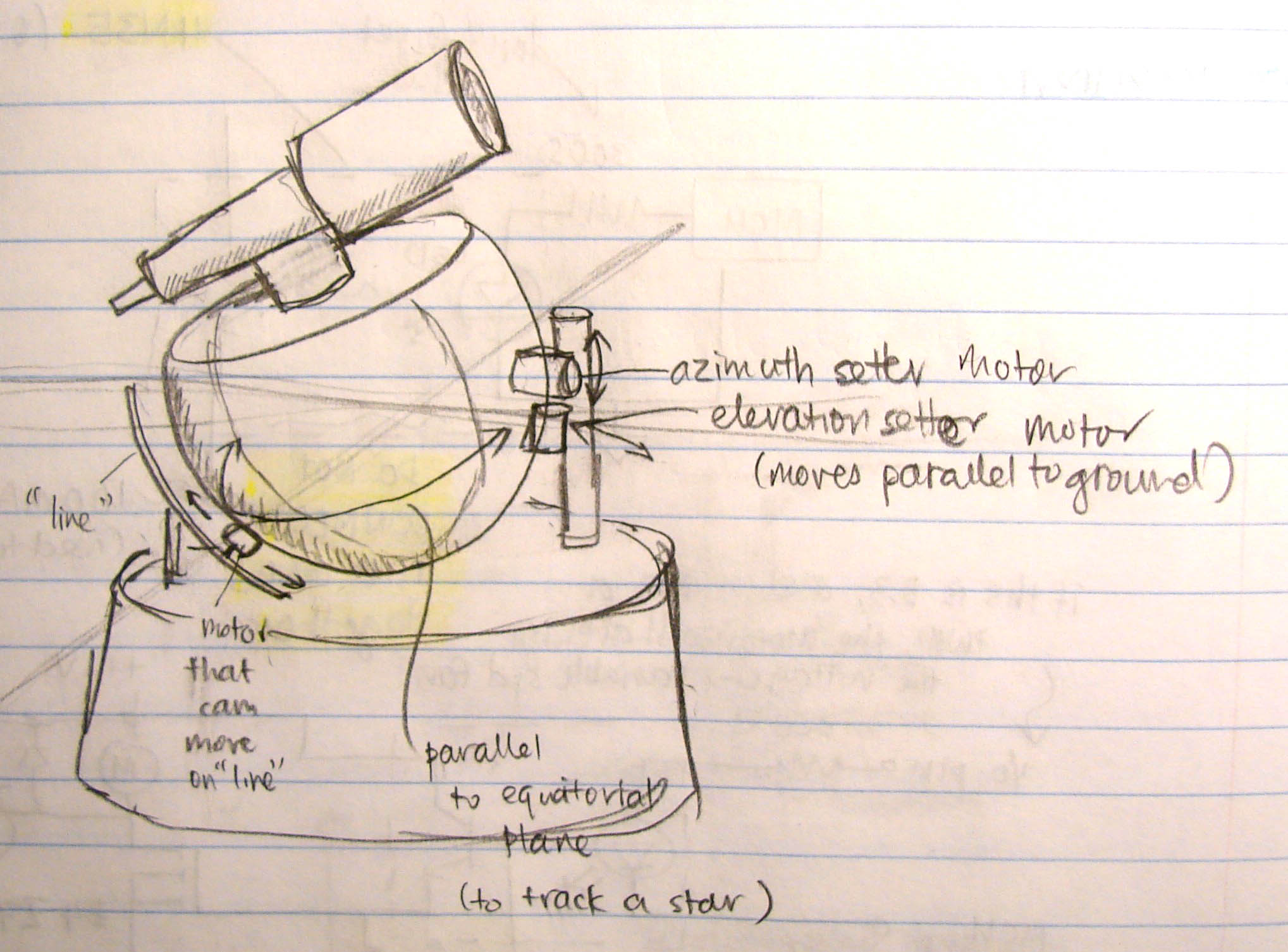
Figure 2.1.1: Original ball mount idea. Click on the picture for a larger version
2.2
Background Math
The precise tracking of a star requires calculations to determine the elevation and azimuth of a star, given its right ascension, declination and exact time at which it is being tracked. The software has to calculate the local sidereal time of the observation, and together with information of the user’s location, is able to determine where the star will be in the sky. The local sidereal time is synchronized to the movement of stars across the sky, just as the local solar time is synchronized to the movement of the sun across the sky. Declination and right ascension are like latitude and longitude coordinates for a star. Declination is measured in degrees from the equatorial plane, while right ascension is measured in degrees or hours right of the First Point of Aries.
Figure 2.2.1: The blue circle describes the locus of the sun relative to the earth. The first point of Aries is the position of the sun relative to the earth during the northern vernal equinox. Image credit: [METU]
2.3
Time Conversion
Before the time can be used to track a star, it needs to be converted to the local sidereal time. This is because local solar time does not progress at the same rate as sidereal time. Suppose the earth did not rotate at all. During the course of a year, to an observer at a point on the earth, the sun will appear to make a full rotation around the earth, because of the earth's motion around the sun. However, the earth does not rotate around the stars, so this "extra" day must be compensated for. Because of the way the earth rotates around the sun, its motion actually cancels out one full rotation about its axis. Thus, while there are 365.25 solar days in a year, there are 366.25 sidereal days in a year.
To convert from local time to local sidereal time, we used the following procedure:
-
The Greenwich sidereal time at our 1 Jan 2007 12AM GMT epoch is 6:38:18.1
-
Each solar day is 366.25/365.25*24*60*60 sidereal seconds = 86636.55031 sidereal seconds, so for each solar day from this epoch, we added 86636.55031 seconds to the time.
-
Each solar hour is 3609.856263 sidereal seconds. Each solar minute is 60.16427105 sidereal seconds. Each solar second is 1.002737851 sidereal seconds, so this was added for the time past a complete solar day.
-
Calculate the longitude offset due to longitude. Each degree of longitude west of Greenwich subtracts 240 seconds from Greenwich sidereal time.
-
Local sidereal time is the number of sidereal seconds past Jan 1, 2007 12AM, added to 6:38:18.1 = 23898.1 seconds, added to the longitude offset, mod 86400.
2.4
Coordinate Reference Frames
There are two reference frames used in our code. One is the ground plane, that is the x- and y-axes span the ground plane, with the z-axis pointing to the zenith. The other reference frame is the equatorial reference frame, used to position the telescope, since it is tilted at an angle parallel to the equatorial plane. In this reference frame, the x- and y-axes span the equatorial plane, while the z-axis points to the star Polaris.
The elevation and azimuth of the stars are calculated based on the ground reference frame, using the following formulas:
Let
H = Object's Hour Angle,
α = Object's Right Ascension,
δ = Object's Declination,
φ = Observer's Latitude,
λ = Observer's Longitude,
A = Object's Azimuth,
e = Object's Elevation (Altitude).
In the actual code, we convert the hour angle to radians for use in the math.h cosine function.
- Compute H = LST - α (in the actual code we use seconds, rather than hours, then convert it to radians)
- Compute A = arctan( -(sin(H) cos(δ)) / (cos(φ) sin(δ) - sin(φ) cos(δ) cos(H)))
- Compute e = arcsin( sin(φ) sin(δ) + cos(φ) cos(δ) cos(H))
The elevation and azimuth then have to be rotated into the equatorial reference frame, so that the telescope is able to know where to rotate to. This is done in the following manner:
Let the latitude of the observer be λ.
Let the vector from the observer to the star be ![]() , where
, where  , and
, and ![]() .
.
We need to rotate ![]() to
to ![]() , where
, where ![]() , and
, and  .
.
With ![]() , we need to find the elevation and azimuth in the equatorial reference frame.
, we need to find the elevation and azimuth in the equatorial reference frame.
New elevation = atan2(![]() [2], 1);
[2], 1);
New azimuth = atan2(![]() [0],
[0],![]() [1]);
[1]);
atan2 produces a result between -pi and pi, so we need to convert this to degrees between 0 and 360.
These formulas were used from what we learnt from the ECE 415 GPS Design class and also sourced from the following [website]
Figure 2.4.1: Rotation from the ground plane to the equatorial plane
2.5
Logical Structure
The MCU acts as a controller for both the user input and the motor turning the telescope. The LCD screen prints out prompts for certain data for the user, who uses the keypad to input the required information. The motor, LCD and keypad are connected to the microcontroller board via the usual 8-pin connections.
The mount is constructed out by milling, drilling and lathing scrap pieces of metal obtained from the machine shop and then built together using screws, hinges and bolts. The design was thought out and drawn by us.
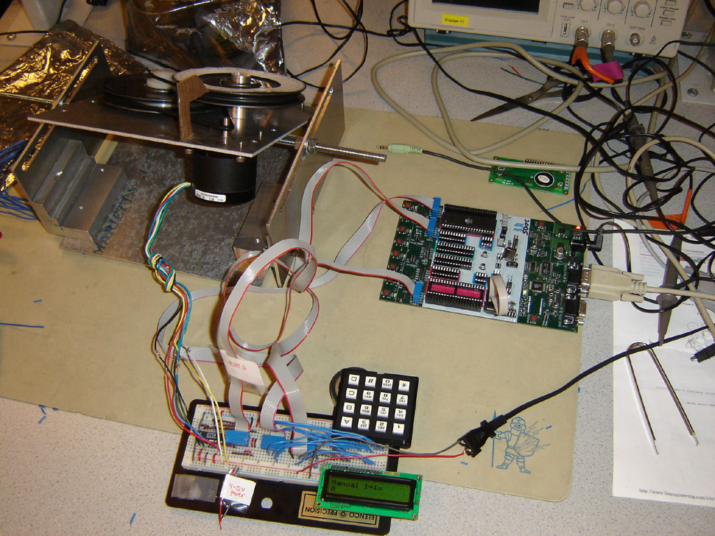
Figure 2.5.1: Picture of our setup. Click to enlarge.
We initially wanted to implement a gear system to move our telescope mount when tracking a star. However, due to difficulty in finding suitable low-cost parts, we decided to forgo the idea and instead implement the pulley system which was much easier and the parts were easier to sample and find.
Figure 2.5.2: High level block diagram of our setup
2.6
Standards
Our telescope mount was designed in accordance to the IEEE standards as specified on their website [www.ieee.org]. The Hours:Minutes:Seconds timekeeping in our program should conform to the Coordinated Universal Time (UTC) standard, although the time inputs are set by the users. Our project does not communicate with other devices.
2.7
Patents, Copyrights and Trademarks
In order for a technology to be patentable, it must be considered both useful and non-obvious. Our telescope mount was designed and implemented by us. However, there are patents that deal with equatorial mounts similar to ours. These include United States Patent 4050318 [Sidereal rate drive mechanism for a telescope mount], and
United States Patent 5062699 [Pivotless equatorial table for a telescope]. None of these patents, however, specifically address a telescope mount built on a platform made from two pieces of metal and a door hinge, moved with pulleys. The LCD, keypad and MCU are widespread devices and would be obvious. They would therefore not conflict with any current patents. We also wrote the software ourselves and would not violate any copyrights or trademarks.
![]()
3
Hardware Design
3.1
Mount
The mount was built by us according to our desired specifications. The pieces making up the mount was constructed using the mill and lathe machines in the Rhodes Hall machine shop. The mount consists of the following parts:
- 1 x Stepper Motor (5681S-54) [click here for datasheet]
- 2 x Door Hinges
- 12 x Screws (10-24)
- 8 x Screws (10-24 Flathead)
- 3 x Pulleys
- 2 x O-rings
- 8 x Washers
- 4 x Bolts
- 1 x Ball Bearing Ring
The base, lid and sides of the mount and the pulley rods were made from scrap metal obtained in the machine shop. These were machined according to the specifications listed in [Appendix B].

Figure 3.1.1: Picture of the front of the mount. Click to enlarge.
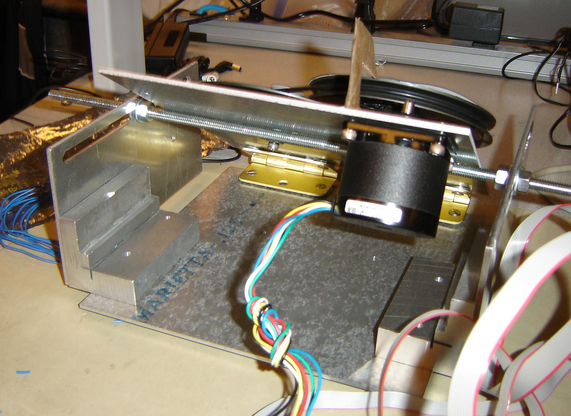
Figure 3.1.2: Picture of the back of the mount. Click to enlarge.
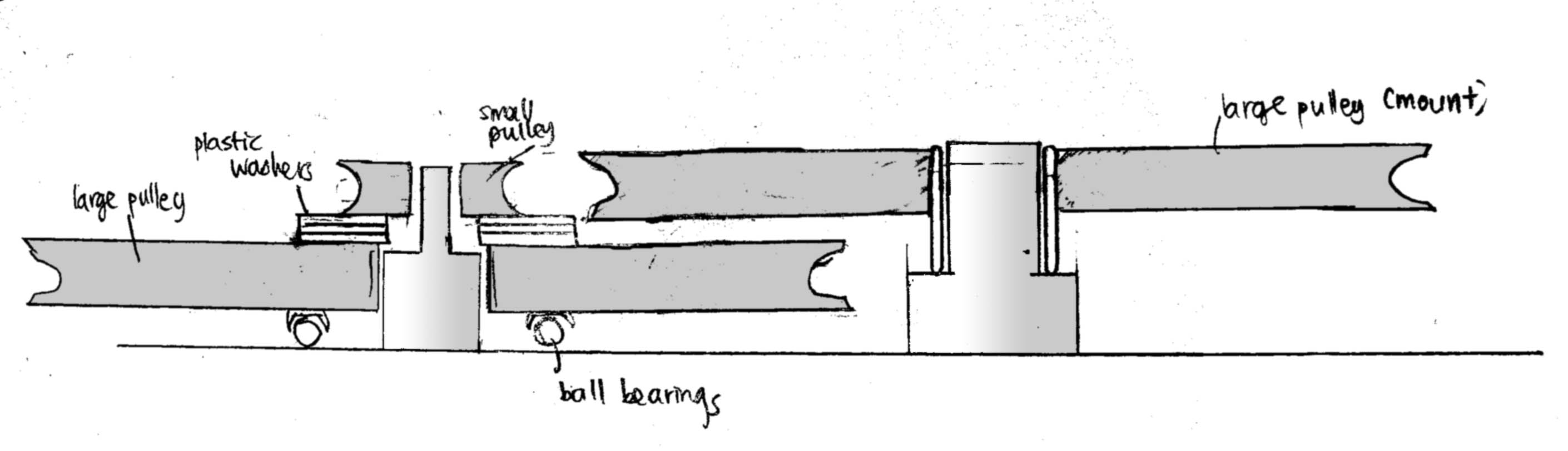
Figure 3.1.3: How we mounted the pulleys. Click to enlarge.
3.2
Circuit
The circuit consisted of the following components:
-
MCU Board:
The ATMEL Mega32 microcontroller is housed on the STK500 board provided by ECE 476. The MCU is powered by a 12V power source. The PORTs A, C and D are used to provide input and output to the LCD screen, keypad and stepper motor controller respectively. -
Stepper Motor Controller:
The stepper motor controller (UDx-2559B-T) was sampled from Allegro. -
Stepper Motor:
The stepper motor (5618S-54) was sampled from Lin Engineering. It moves 1.8 degrees per step. The power needed for the motor is around 12V and 1A. -
Power Supply:
Our power supply for the motor is a 9V-12V supply. This was scavenged from leftovers from last year’s projects. -
LCD Screen:
The LCD screen that we used was the one provided in the ECE 476 lab. This screen was used to output prompts for user inputs. -
Keypad:
The keypad we used was the one provided in the ECE 476 lab. This keypad is used by the user to input the desired parameters for using the telescope mount. -
Whiteboard:
We used the provided protoboard to provide access to the LCD screen, keypad and to house the stepper motor controller.
As we intended, the stepper motor is connected to the pulley system via an O-ring. As the motor turns, the pulleys rotate and turn the telescope as needed. The elevation of the telescope can be adjusted by sliding the horizontal rod back and forth the slit along the side plates.
One calculation that we had to take into account here was the step-down of the rotation ratio between the motor and the pulleys. We had to had a 1:80 step-down ratio in order to accurately position our telescope. By utilizing pulleys of different radii, we were able to achieve the necessary step-down.
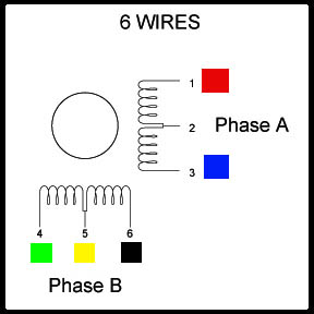
Figure 3.2.1: Wiring Diagram for the Stepper Motor
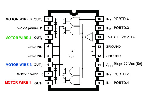
Figure 3.2.2: Wiring diagram for the stepper motor controller (UDx2559B-T). Click to enlarge.

Figure 3.2.3: Whiteboard, Keypad, LCD, stepper motor controller. Click to enlarge.
3.3
Custom Board (which failed, sadly)
We tried soldering our own custom PC board and protoboard to save costs. These worked well all the way throughout the lab until they suffered a catastrophic failure without reason. We tried for hours to debug the circuit boards, with help from the TA's, but were unable to discern a reason for the sudden failure. We had to use the STK500 instead. Fortunately, we were only just able to meet our budget, thanks to the large amount of scrap we managed to acquire at the Emerson Lab.
![]()
4
Software Design
4.1
Motor Control and Modes of Operation
Our program consists of a few main parts. The main state machine controls the user inputs, while two separate functions calculated the local sidereal time and the elevation and azimuth of the desired star to be tracked. Other functions include control for the keypad and the motor. There are two modes of operation: manual and automatic. In manual mode, the user uses the scroll buttons to move the motor as he/she wishes. In automatic mode, the user enters the star coordinates (or chooses them from a list) and his time and location, and the program will automatically calculate where to point the telescope to. Tracking can be done in either mode.
Initialization Code
This code initializes all the variables used in the project code and resets all state machines to their initial states. PORTs D, A and C are initialized for motor controller output, keypad input and LCD output respectively. Both Timer0 and Timer1 on the ATMega32 are also both initialized here.
The initial date variables are set to initialized to Jan 1, 2004, 12 midnight GMT.
Star information is stored into arrays here as well.
Timer0 Interrupt
Timer0 interrupt is called every millisecond. This gives us an accurate internal clock that keeps track of the time that has elapsed.
Timer1 Interrupt
Timer1 interrupt is called every 1/1000 sidereal second. This is so as to rotate the mount to track the star as it moves every sidereal second.
Motor Control Code:
We wrote our own code to that communicated with the motor through the stepper motor controller. The stepper motor has 4 coils that when sent certain signals in a certain sequence would step the motor clockwise or anticlockwise either in full or half steps. From Figure 3.2.1, the coils were asserted in the following order: 1, 4, 3, 6, 1,... for full steps, and 1, 1+4, 4, 4+3, 3, 3+6, 6, 6+1, 1,... for half steps.
4.2
Star List
The program also has a list of stars that the user can choose to track, without having to manually input declination and right ascension coordinates. The following stars are available: (Coordinates in the square brackets are the declination and right ascension of these stars, and the name in the brackets is the Constellation the star is in)
- Polaris (Ursa Minor) [90, 37.25]
- Alcor (Ursa Major) [55, 201.25]
- Algol (Perseus) [41, 47]
- Arcturus (Bootes) [19, 213.75]
- α (Aquarius) [0, 331.25]
- Betelgeuse (Orion) [7, 88.75]
- Capella (Auriga) [46, 79]
- Dubhe (Ursa Major) [62, 165.75]
- Eltanin (Draco) [51, 268.75]
- ε (Sagittarius) [-35, 376.25]
- Markab (Pegasus) [15, 346]
- Mirach (Andromeda) [36, 17.25]
- Pleiades (Leo) [24, 56.25]
- Pollux (Gemini) [28, 116.25]
- Regulus (Leo) [12, 152]
- Rigel (Orion) [-9, 78.5]
- Sirius (Canis Major) [-17, 101.25]
- Vega (Lyra) [39, 279]
See the [Star Chart]
4.3
Time conversion and Azimuth/Elevation calculation
This takes in the solar time variables and calculates the local sidereal time according to the math discussed above in Background Math. Our reference Greenwich Sidereal Time at our 1 Jan 2007 12AM GMT epoch is 6:38:18.1
Using the right ascension and declination, we calculate the elevation and azimuth in radians. We then perform the coordinate frame rotation (as discussed in Background Math) to obtain the true elevation and azimuth of the star relative to our location. Special attention was paid to the units. All angles were converted to decimal degrees, and times converted to seconds. For the math.h trigonometric functions, the degrees were converted to radians.
4.4
Keypad Controls
The keypad control code was reused from the previous ECE 476 labs with the addition of a few buttons. The standard 0-9 keys were preserved, with the addition of "-" and “.” keys for floating point input. A “backspace” button was also included to correct typing errors. With a star list that we had to display on the LCD screen, we also decided to implement “Scroll Up” and “Scroll Down” buttons. These buttons are also used to manually calibrate and move the telescope mount.
4.5
Program Flow
Figure 4.5.1 Program Flow State Diagram
The state diagram here shows the number of steps that the program takes the user through to obtain the desired parameters to perform the star tracking. Data such as time, longitude, latitude and star information (right ascension and declination) have to be inputted by the user before the program is able to use the motor to move the telescope to track the star. We also have a manual tracking mode that requires no data input. We need the following data:
- Latitude (decimal degrees)
- Longitude (decimal degrees)
- Date (MMDDYYYY - from 2007 to 2010)
- Time (HHMMSS)
- Timezone (-14 to +14)
- Application of DST (1 or 0)
- Declination of star (decimal degrees)
- Right Ascension of star (decimal degrees)
After the users input the required data, they are given an option on their subsequent use of the mount to keep using the old information (i.e. track the previous star). This gives them an easy way to automatically revert to the star that they have been tracking.
The state machine also consists of different tracking modes which the user can choose from.
- Fast Rotate
- The program uses this mode to move the telescope orientation towards the desired star to be tracked. - Calibrate
- Users will be able to use this mode to center the telescope on the desired star before enabling automatic tracking. Moving the telescope in this mode does not affect the stored azimuth variables, so the telescope can be calibrated to point to the correct direction. - Normal Track
- The motor on the mount will automatically turn the telescope to track the desired star at the correct speed. - Manual Track
- Users are able to manually operate the mount to track the telescope by sight instead of using the automatic track functions.
![]()
5
Results
5.1
Timing Accuracy
The telescope mount is functional and working properly. The state machine that we designed for user input works as intended in acquiring the required data for star tracking. The telescope mount rotates the telescope right after the calculations of the star position are done. There is also little or no downtime between using the keypad buttons to calibrate the telescope mount’s orientation.
The local sidereal time interrupt executes every 15956 cycles (at 62.5ns) to increment the local sidereal time clock. This is approximately 1/1000 of a sidereal second. In reality, this clock should be executing every 15956.16 cycles. However, this is not possible with the ATmega 32. Thus, we gain 0.28415 cycles every 1/1000 sidereal second, or 0.63934 sec every 10 hours. This is acceptable since we do not intend to be running the mount for more than 2-3 hours. There is also a limit to the floating point accuracy when calculating the number of seconds that passed since our epoch.
5.2
Rotation Accuracy
With the high step accuracy of our motor and our step-down pulley system, we were able accurately track the position of a star to within approximately 0.01 degree. However, the rotation of the telescope to the star's position has an accuracy of 0.5 degrees, due to the accuracy of floating point division. Our various tracking modes also work as intended; the user is able to calibrate the telescope manually and fast tracking mode for the telescope mount rotates the telescope ten times faster. We are satisfied with the construction of the mount as it is stable and solid enough to support and turn a telescope.
5.3
Safety
Safety was observed throughout the construction of the mount. We complied with all the rules and regulations of the Emerson Lab machine shop while using the machines. We enrolled in the Basic Machining course taught by George Petry to be fully certified to use the red apron machines - the mills and the lathes. Safety goggles were worn at all times in the machine shop, and we took care to observe all the safety procedures while using the machines. In the ECE 476 lab, we made sure to solder our boards properly and safely. All this was also done in the consideration of those working with and near us. Therefore, no one was hurt during the process of the entire project.
5.4
Usability and Interference
We did not in any way interfere with other people’s projects, making sure that our mount parts and boards were kept away from others. The user interface of the telescope mount is simple and easily understandable. This makes is usable for almost everyone.
![]()
6
Conclusion
6.1
What would we do better next time? (or if we had more time)
The initial idea of building a telescope mount was extremely daunting. The designing and machining aspects were deemed too hard and time-consuming that we were worried that we would not finish the project on time. However, after we scaled down our designs and obtained the materials, we were able to make relatively quick progress on the mount.
The code was written with relatively few bugs. The few problems which arose was when we were dealing with printing float variables to the LCD screen and also scrolling through the list of stars on the LCD screen. The two functions that we used to calculate LST and rotate coordinate frames were also particularly challenging to write.
We were able to overcome these few difficulties and finished the project. We are extremely happy that the telescope mount is fully functional.
Given more time or a larger budget, we would add a Hall sensor to our mount, which would detect the rotation of the mount and provide feedback as to its actual direction, to enable us to more accurately track a star. We would also add a motor to control the elevation of the mount, so that the process can be more automated. Currently the user has to manually adjust the elevation of the mount.
6.2
Intellectual Property Considerations
Other than the formulas obtained from a website mentioned earlier, all circuits, digital code and mechanical designs were built and written by Ian Quek and Kevin Goh. There are no patent opportunities for our project. We did not have to sign any non-disclosures to get sample parts.
6.3
IEEE Code of Ethics
Our project was designed and built by accordance of the IEEE code of ethics:
We, the members of the IEEE, in recognition of the importance of our technologies in affecting the quality of life throughout the world, and in accepting a personal obligation to our profession, its members and the communities we serve, do hereby commit ourselves to the highest ethical and professional conduct and agree:
- To accept responsibility in making decisions consistent with the safety, health and welfare of the public, and to disclose promptly factors that might endanger the public or the environment;
We took all precautions in machining our mount safely and also to observe all safety regulations while in the lab.
- To avoid real or perceived conflicts of interest whenever possible, and to disclose them to affected parties when they do exist;
We spoke with our TA and professors throughout the course of the project for advice and consultations.
- To be honest and realistic in stating claims or estimates based on available data;
We have specified our limits and goals clearly throughout the project. We have also been honest about reached goals and unreached goals in this report.
- To reject bribery in all its forms;
We were not offered any bribes for our work. Any donations of materials are stated as such.
- To improve the understanding of technology, its appropriate application, and potential consequences;
We wanted to expand our project to include both technical and mechanical aspects in order to learn more.
- To maintain and improve our technical competence and to undertake technological tasks for others only if qualified by training or experience, or after full disclosure of pertinent limitations;
We never tried any hazardous and potentially dangerous tasks that would not be satisfied by our technical knowledge in this project.
- To seek, accept, and offer honest criticism of technical work, to acknowledge and correct errors, and to credit properly the contributions of others;
We have stated clearly our sources of information throughout the project.
- To treat fairly all persons regardless of such factors as race, religion, gender, disability, age, or national origin;
- To avoid injuring others, their property, reputation, or employment by false or malicious action;
As mentioned, we observed all safety rules and regulations.
- To assist colleagues and co-workers in their professional development and to support them in following this code of ethics.
6.4
Legal Considerations
There are no legal considerations for us since we do not transmit anything.
![]()
7
Appendices
7.1
Appendix A: Commented Program Listing
Please click on this [link] for the C code.
7.2
Appendix B: Schematics and Machining Diagrams

Figure B.1: Front of Mount: Concept Art
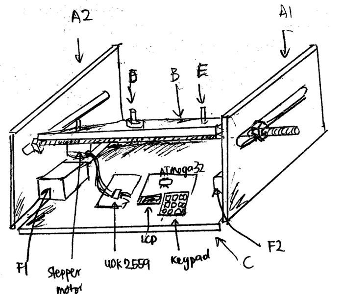
Figure B.2: Back of Mount: Concept Art
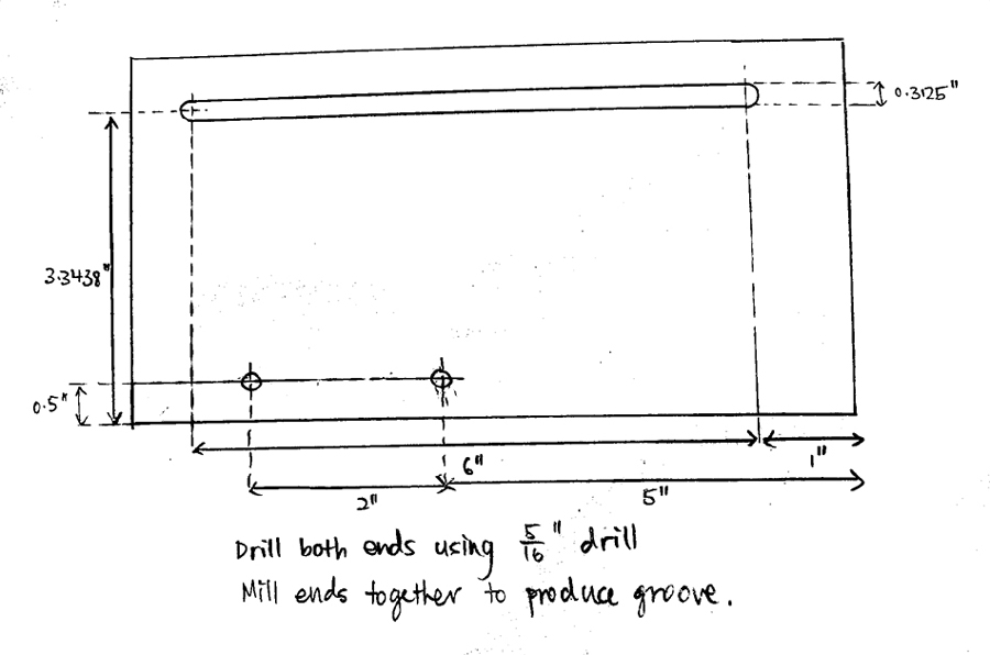
Figure B.3: Part A: Holder for threaded rod to keep the mount tilted
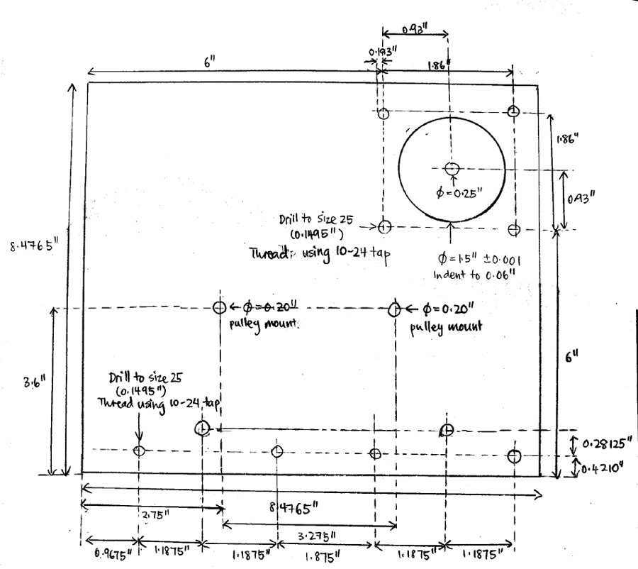
Figure B.4: Part B: Mounting sheet for the pulleys and the motor
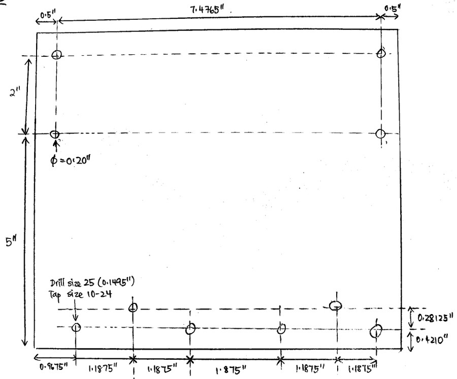
Figure B.5: Part C: Base sheet
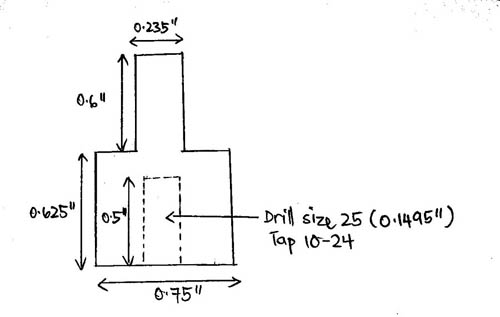
Figure B.6: Part D: Initial Pulley Mount - for the pulley that is connected to the motor
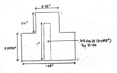
Figure B.7: Pulley Telescope Mount: For the telescope to be mounted on
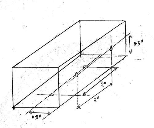
Figure B.8: Part F: Holder for Part A. Connects the base to the threaded rod holder.
7.3
Appendix C: Cost Details
|
$8 |
|
$15 |
|
$8 |
|
$6 |
|
$5 |
|
$6 |
|
Free (sampled from Lin Engineering) |
|
Free (scrap metal from machine shop) |
|
Free (given by machine shop technician) |
|
Free (given by machine shop) |
UDx2559B-T |
Free (sampled From Allegro) |
|
$2 |
|
Free (given by friend) |
|
$50 |
7.4
Individual Tasks
Ian Quek:
Wrote main code
Soldered custom board
Machined Parts B, C, D and E (see Appendix B)
Wired up motor controller
Sampled Motor
Sampled Motor Controller
Converted Project writeup to HTML
Kevin Goh:
Soldered protoboard
Machined Parts A and F (see Appendix B)
Wired up LCD and keypad circuit on Whiteboard
Wrote keypad control code
Wrote project write-up
Made purchases
7.5
References
- Instructions on how to convert Local time to Local Sidereal Time (there is an error here. Instead of subtracting 236s, we should be adding)
- Wikipedia - Gear Ratio
- How Stuff Works - Gears
- The Equatorial Platform
- Star Ephemeris
- Coordinate Reference Frames
- Star Charts
Datasheets
Vendor Sites