This project implements a microcontroller based temperature
regulator which can be controlled via the Ethernet port on any common
personal computer.
As the world becomes more networked, the
power of our ability to communicate with many different systems
instantly continues to prove it's worth in maximizing utility and
convenience. The common consumer now has more options then ever for
networking access from hand held Blackberries to common Internet
access through a personal computer. Many systems would only benefit
from being accessible from any network connection, including many
common devices that previously would never be considered to be
networked, such as a coffee machine or refrigerator. In our case, we
pair a microcontroller with a commercial Ethernet solution via SPI in
order to allow the world at large to communicate with the
microcontroller, and vise versa. Communication in our device is done
through a modified UDP controller accessed via the command prompt and
third party software. As a proof of concept, we used the ethernet
controller to sample and set temperatures for a closed system.
Temperature sensing is done through the analog to digital converter
on the microcontroller and heating and cooling is done using the
pulse width modulator in conjunction with proportional control theory
to allow for a stable transition to the desired temperature.
Rationale
Although the benefits of Ethernet-capable
microcontrollers are numerous, we focused on remote sensing and
control benefits allowed by the technology. In theory similar systems
could be used to cool or heat different parts of a house, office,
car, lab or other area that needs remote temperature control from
anywhere in the world. This specific implementation was chosen as a
possible value-add to a product created by a Cornell graduate
student. His product, KoolKennel ostensibly uses a similar
methodology of heating or cooling pet carriers. By adding Ethernet
capability, pet owners can both check and adjust the temperature of
the kennel remotely. The general concept of remote temperature
measurement and control has other lucrative applications in a variety
of other industries as well.
Logical Structure
The
design was divided into two equally important parts. First, we needed
the microcontroller to measure and regulate the temperature in our
system. We used a thermistor with the analog to digital convector on
the microcontroller, and a peltier device attached to a fan to cool
or heat our system. Due to the size of our system compared to our
peltier device we needed to not only change our temperature quickly
but to stabilize at a point. Thus we chose to implement a version of
a proportional controller. The peltier device is controlled by a H
bridge implementation to increase the voltage driving the device. The
Ethernet connection to the device provides our only means of
communicating with the system and thus was the other significant part
of the project. The first step in establishing Internet connectivity
was to find a means of interfacing our microcontroller with Ethernet
connectivity. Research on similar projects showed that available
options included chips from Realtek, SMC, and Microchip. After
finding no full implementations for the Microchip controller written
on the Codevision compiler, we decided to take the problem on and
implement it ourselves.
Hardware/Software Trade offs
Since the analog to digital converter on the microcontroller
could only sample one reading at a time we limited ourselves to using
only one temperature sensor in the device. While a larger space might
require a sensor network to accurately measure the entire system, our
environment was small enough that we could use only sensor to
satisfactory results. Additionally, since we used a motor to increase
air flow into and out of the system we introduced an irremovable
amount of thermal noise into our system that would vary the
temperature constantly and thus would keep changing the input to the
ADC on the microcontroller. This meant that we would need to
introduce a software filter for the temperature reading. Additionally
our PD control was limited by this thermal noise, and we can only be
as accurate as our reading. Due to our limited budget we chose to
make our own boards, but this increased the amount of inductance in
the system. Thus implementing the three way handshaking protocol was
much more difficult then we first perceived as the analog hardware
introduced noise that would invalidate packets. UDP protocol provided
a simple enough system that would not be affected by the
electromagnetic reflections that might result from the system, and
thus determined our choice of protocol. Our choice in using UDP
necessitated additional code to interact with the device through
Windows. Fortunately, free third party software referenced in the
appendix was already written to achieve this.
Standards
We followed a wide variety of standards for Ethernet, Address
Resolution Protocl (ARP), Internet Protocol (IP), ICMP (Internet
Control Message Protocol) TCP (Transmission Control Protocol) DHCP
(Dynamic Host Configuration Protocol). Ethernet needed to be built so
that packets could go in and out; ARP was to be built on top of
Ethernet to allow for other computers to discover the existence of
our controller; IP needed to be built in order to provide transport
of our packets; ICMP was to be built so that we could effectively
ping our controller; TCP was to be used as the main transmitter of
packets; DHCP was to be enabled so that a router could dynamically
assign an IP address to our controller. This report is not intended
to be a discussion of these protocols and their complete function as
that is a class in and of itself, but we followed all protocols as
specified here.
Patents and Legal Considerations
While our design
intended to enhance existing temperature controlled systems, our
novel way of achieving this does not infringe on any patents that we
could find.
Overall Design
Our choice to use the Microchip ENC28J60
determined many of the hardware choices that we made in our design
process. As the device runs off of 3.3 volts instead of logical 5
volts, we originally envisioned stepping up the voltage using a pack
of AND gates. Since the Ethernet controller needed to be run at a
high frequency we were not able to spec AND gates fast enough that
would both fit into our budget and have slew rates fast enough. Thus
we chose to run our microcontroller at 3.3 volts as well. Resistors
and connections between the ENC28J60 were determined by the ENC28J60
data sheet, as well as the connections between the Ethernet jack and
the Ethernet controller. The Ethernet jack features not only
transmission and receive lines but functional LEDs as well, who also
operated on the 3.3 volts. Since we needed both a 3.3 volt line and a
12 volt line for our H-bridge we used a converted ATX power supply
that we already owned.
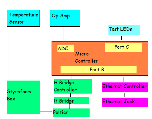
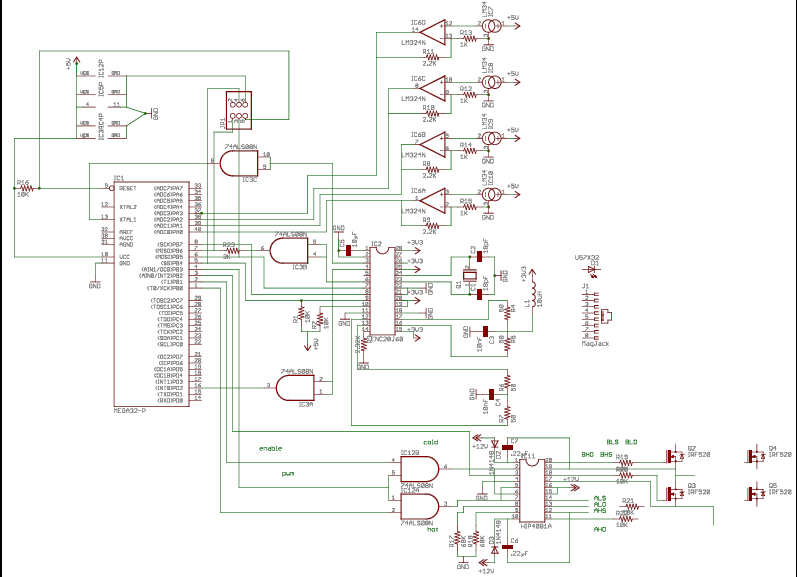
The following schematic shows our
overall design of the microcontroller, with all the ports
appropriately attached (please click for larger).

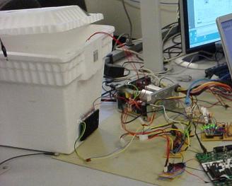
Temperature Measurement and Control
Measurement of
our system was performed by measuring the voltage across a variable
thermistor, specced to have 10mV / degree F. The ADC on the
microcontroller however needs to be more precise then that, however,
and so we fed this same voltage across a simple op amp specced to
have a gain of three. With the microcontroller operating at 3.3 volts
this allowed us to detect temperatures up to 110 degrees F. Our
temperature contained system consists of a large styrofoam box whose
only interface with the outside enviroment is our peltier element
attached to a fan to increase circulation. This fan, however,
generated enough heat that we could not sufficiently cool the system
as we had hoped we would be able to. We were still able to
sufficiently heat the system above room temperature and keep it
there, but due to thermal leakage into our system and the heat
generated by the fan we were not able to cool the system below 70
degrees. At first we were not achieving the thermal rate of change
that we expected, but including another external fan on the device
allowed us to cool the peltier, a differential device, and achieve
larger thermal changes including additional cooling.
The
thermal energy that the fan adds into the system is also seen in
measuring the thermistor. The thermistor, pickup up this slight
variation, amplifies this variation for the ADC. Since our controller
has a limited reaction time to cooling and healing, we needed to slow
the measurement of our system as well and decided to implement a
running average filter and impose an artificial time between
temperature measurements. The running average filter measures the
last eight inputs and we use this averaged output to determine the
temperature. This allowed us to fine tune our thermal controller to a
satisfactory level and reduced the amount of variation that the fan
introduces. Before integrating the thermal part of our system we
relied heavily on LEDs controlled by the MCU, but due to cost we did
not include them in our final design as they only served in debugging
purposes.
Our controller is a variation of traditional PID
control theory. Using proportional gain control we were able to tune
our system empirically to have both fast and stable results. PID
control reduces ringing, increases gain and increases stability given
the right parametrics. Proportional gain depending on how far the
system is from the desired state increases overall gain while
calculating the derivitive of the gain reduces ringing by introducing
damping. Further discussion of such techniques can be found on the
pages in the appendix. Here is one example of how a similar controller
would work:
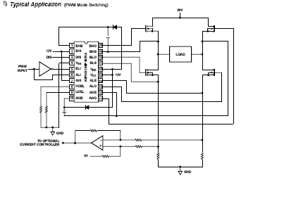
To control the power going into the system we used a
combination of the pulse width modulator on the microcontroller and
an H bridge. The H bridge drives the peltier with almost four times
the voltage and thus four times the thermal gain then the
microcontroller can provide on 3.3 volts. The H bridge also allows
the circuit to switch from heating to cooling almost instantly. The
PWM provides us with a means of controlling the duty cycle on the
device, and thus a way to control the power with constant voltage but
differing amounts of time where the device is on. The microcontroller
interacts with the h bridge via a specifically designed H bridge
controller which inputs three different control signals and a PWM
signal and drives the H bridge accordingly. We have three distinct
states in our design: heat, cool, or disable the system. Using the
following provided specs for the controller we attached the
microcontroller.
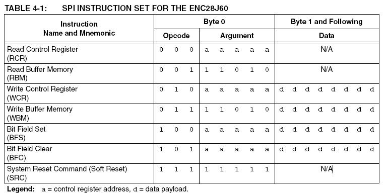
The first step in getting the chip to talk to the
microcontroller was writing the appropriate methods to implement the
operating instructions. Some of this was made more difficult because
writing and reading certain registers required extra logic.
Thankfully, the methods for writing these registers were fairly easy
due to good documentation from Microchip. Identification of the
specific registers and which ones required the different addressing
methods was done by taking an existing .h definition sheet provided
by Microchip for interfacing with their PIC chips and modifying it to
suit our purposes. A method automatically looks up the register when
addressing it and applies the appropriate write method, with one
exception: Physical registers, called PHY registers, have their own
write method that must be called explicitly by the programmer. This
is acceptable since PHY writes are done a total of once during
initialization and never during operation. Once the instruction set
was appropriately implemented, the next step was to go through
initialization.
Initializing the chip is a fairly easy
process and is well laid out by the datasheet. Additionally, the
Microchip implementation of the initialization routine helped in
explaining what was going on. The only real sticking point in the
process was in writing the filtering commands. Basically, the filters
on board the ENC28J60 allow for packet discard and accept long before
the microcontroller sees them, allowing for more efficient use of the
buffer memory on board the ENC28J60, saving SPI time, and saving
cycles done for reading. Unfortunately, the way the filters were
initially set allowed for the discarding of packets that we actually
wanted to see. As such, the filter ended up being disabled, since the
appropriate settings that would allow our combination of packets to
be accepted could not be found. After initialization, the next step
was to write Transmit and Receive methods. These were taken directly
from the datasheet, and work nearly flawlessly. We had two issues
with these: first, we found was that the chip will not transmit the
first time the Transmit function is called, and only seems to start
transmitting after it is called a second time. Secondly, the
microcontroller seems to lose packets sometimes. We were unable to
ascertain the causes of these problems; thankfully, the speed of the
Ethernet means that retransmitting lost packets is not a huge
problem.
Building the Ethernet protocol suite was fairly
easy: all that needed to be done was switch the source and
destination Media Access Control (MAC) address, which is a 12 octet,
unique number that identifies the two addresses. ARP was a bit more
complicated: to implement ARP, the microcontroller needed to search
for a packet that was MAC- addressed to FF:FF:FF:FF:FF:FF and had an
IP address that matched its own. Once it found this, it built a reply
that would allow for the computer that sent the request to associate
the controller's IP address with its MAC address, so any requests to
that IP would be sent to that MAC address. IP implementation was a
bit trickier, with the checksum field being notably difficult to set
up correctly. The checksum consists of the 16 bit one's complement
addition of the fields of the IP header. Other IP fields were easier
to set. ICMP was also a pain to implement for the same reason: the
checksum field did not seem to work properly and required a litany of
recoding before the protocol worked correctly. This was compounded by
the issue of the ENC28J60 initially dropping ICMP packets, which made
debugging an exercise in frustration until the filtering issue was
resolved.
TCP implementation was initially to be implemented
in order to allow for HTTP, or web pages, to be the mechanism by
which the controller was accessible. This was highly desirable, as
nearly every internet-connected computer has a web browser, which
would make the controller ubiquitous and require no specialized
software for interfacing. The methodology for connecting via TCP was
highly simplified and was to operate on the same principle as Guido
Socher’s GCC TCP implementation
(www.tuxgraphics.org), which drastically simplified TCP operations.
By treating every TCP request as single packet transmission protocol
(without delving into the protocol in too much depth, most TCP
connections are left open until all the packets have been sent, which
requires some careful management of states), much of the complex
logic and negotiation can hypothetically be left out. IN our case, we
attempted to implement the initial response to a TCP request
(SYN/ACK), an intermediate response (ACK), and the final response
with data (DATA/FIN/ACK). During coding, we managed to get the
SYN/ACK packet working properly, but after a significant time spent
attempting to get the remainder of the protocol to work correctly, it
was abandoned in favor of a simpler protocol.
The replacement
protocol was User Datagram Protocol (UDP), an extremely lightweight
protocol that is also omnipresent on the Internet in various forms.
The plus side of this protocol technology is that the implementation
is much simpler than TCP. The minus side is that implementing certain
portions of our design, like DHCP and HTTP, was therefore impossible.
Can I build this?
Ideally all code contained here
with referenced software will allow any user to implement their own
design. All third party software referenced in the appendix is free
for download, but documentation would have to be followed in order to
achieve the same results. Building off of our design, we speculate
that it would be feasible to implement a GUI Matlab script for ease
of use, but unfortunately due to lab limitations with the software we
were not able to test and design our own script.
Device Speed
Two different interfaces were on our
device, one communication line between the microcontroller and the
Ethernet line, and the other the thermal interface of our system.
Since we were using simple UDP communication on the Ethernet
operating, the speed of the device was determined by the Ethernet
cord and jack and the speed of the MCU. Since our MCU was operating
at 12 MHz as per the specs on the Ethernet controller, this is
theoretically the fastest that we could interact with the system, but
any Ethernet testing that we did showed responses faster then
milliseconds. Since we intended for this device to be a human
interface we feel that the device speed is largely determined by the
human interaction, but if integrated into a larger C code the speed
is again limited primarily by the MCU speed.
Thermal control,
however, is not limited by the MCU clock but instead by the thermal
rate of change of our system. Due to the thermal inertia of any given
system, we could only change it as powerful as our peltier device
would allow. Fortunately, both the Ethernet controller and the
thermal controller ran concurrently so that one would not limit the
other. We empirically measured our fastest thermal rate of change to
be up to 1 degree / 10 seconds, which we felt was decently fast, as
any given temperature could be achieved in a matter of minutes,
especially if heated to that temperature. While it took up to 20
seconds for the peltier to achieve it's highest or lowest temperature
given a full duty cycle by the PWM, the minimum time that we could
change temperatures then would be limited by that.
Accuracy
While we experienced an almost 100% accuracy from the UDP
Ethernet controller, with only very rare packets being dropped less
then 1% of the time, the temperature controller was slightly less
accurate. Due to the thermal noise introduced by the fan we were only
ever able to measure 2% degree of accuracy. Achieving a set
temperature by the controller was also directly affected by this, and
the best accuracy we were ever able to achieve was around 3% (plus or
minus one degree of Fahrenheit). To increase frequency custom boards
should be considered, along with a passive filter between the
thermistor and the op amp, although this would have put us over our
budget limit.
Safety and Environmental Interference
While building our device we kept outside interference both into
and out of our system to a minimum. Operating at higher temperatures
might lead to thermal leakage, and any nearby thermally sensitive
devices would be effected. In addition, if our device were extended
beyond the ranges we achieved in lab of 70 to 104 degrees, extreme
high or low temperatures could prove to be dangerous to anyone who
might enter the contained system.
The end result of our design was a workable temperature controller
that was indeed able to be interfaced on Ethernet and the Internet at
large, but not at the level of transparency we originally set out to
produce. Thermal control was not as accurate as we would have hoped,
and several suggestions as discussed previously might have helped us
increase our accuracy such as introducing a low power fan or more low
pass filters in the design. Indeed, even using custom PCBs would have
helped by reducing wiring complexity, inductance, and detrimental
capacitance. To interface better with the user, we would have created
our own custom C or matlab script, but the focus of this project was
on microcontroller design. Indeed, although we may reflect on things
we would have done differently, we still achieved an Ethernet
controlled thermal system!
Intellectual property
considerations.
In implementing the Ethernet we heavily
borrowed from existing C libraries created by Guido Socher
(www.tuxgraphics.org). Care was taken to give credit where credit is
due and re engineer where credit cannot be given. All propriety
information is documented in the code. In order to make this a
marketable product all portions of code originally written by Mr.
Socher would need to be re-engineered and implemented differently so
as to not violate the rules of the GNU GPL.
Ethical
Considerations
If our design were to be implemented on a
larger scale where the environment contained living beings, then IEEE
ethical standards would apply. Our device was not designed for
harmful means, but extra security would be needed so that outside
forces could not access and control the temperature to detrimental
effects. On our small scale, our product could cause no harm as it
only operates in a temperature range from 70 degrees to 100 degrees,
but if a better temperature regulator were implemented on a larger
system where pets were contained, for example, then the network
access would have to be secure. In order for the device to be
practically implemented more safety features would need to be
implemented, such as critical point failure or thermal ventilation.
Schematics
Budget
|
Part |
Supplier |
Cost |
|---|---|---|
|
Peltier |
Bgmicro |
$8.00 |
|
Mega32 |
LAND |
$8.00 |
|
Boards |
LAND |
$2.00 |
|
ENC28J60 |
Microchip |
SAMPLE |
|
74HCT08 |
Digikey |
$0.50 |
|
L829-1J1T-43 |
Digikey |
$6.40 |
|
25 MHz Crystal |
Digikey |
$0.70 |
|
HIP4081A |
Digikey |
$3.00 |
|
IC Sockets |
|
OWNED |
|
IRF520 |
|
OWNED |
|
LM324N |
Digikey |
$0.45 |
|
Styrofoam Box |
|
OWNED |
|
LM34 |
National |
SAMPLE |
|
Power Supply |
|
OWNED |
|
Heat Sinks |
|
OWNED |
|
TOTAL |
|
$29.05 |
Tasks
|
Task |
Responsible |
|---|---|
|
Network Protocol |
Mark |
|
UDP Code |
Mark |
|
TCP/IP Code |
Mark |
|
PID Controller Research |
James |
|
Thermal Measurement |
James |
|
Thermal Regulator |
James |
|
Debugging |
Both |
|
Hardware Design |
Mark |
|
Hardware Build |
Both |
|
Write up |
Both |
|
Website |
James |
References
Mega
32 documentation
Ethernet
controller documentation
H
bridge controller documentation
Peltier
devices
PID
Overview
PID
specifically for Mega AVR
Guido Socher www.tuxgraphics.org
provides udpcom software, microntroller libraries
Ethereal
network protocol analyzer
Suppliers
Digikey
Microchip
National
Semiconductors