ECE
476 Final Project
Ultrasonic
ParKontroller
James Juwon Lee (jjl49)
Maurico Rodriguez Saenz (mar97)
Spring 2007
Introduction
Are
you afraid that your brand new Hummer is going to get scratched while parking
it in a tight space? Do you have
trouble backing your large Mercedez S-class into your small garage? Fear no more! Our ultrasonic ParKontroller can sense
how far you are away from the wall or a hidden object behind your car and warn
you visually and audibly using LEDs and speaker respectively.
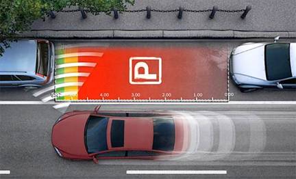
Courtesy
of Bosch.com
High Level Design
Rationale of our project
A
significant portion of the people around the world owns car or are daily
drivers. In fact,
Logical Structure
The
basic theory behind the ParKontroller is the Sound Navigation and Ranging
(SONAR) technique that is used for finding the distance and direction of a
remote object underwater by transmitting sound waves and detecting reflections
from it. First, a series of short
ultrasonic pulses are transmitted using a transducer that changes voltage into
sound waves. The transmitted pulse
is reflected off an object, and the reflected wave is then received by another
transducer that converts sound waves into voltage. The transmitted signal is also known as
the ‘ping’ and the received signal is known as the ‘pong’. By counting the elapsed time between the
ping and the pong, the distance between the device and an object can be easily
calculated by multiplying the elapsed time with the speed of sound. Note that the time measured represents
the time it takes a pulse to travel to an object plus the time it takes to
travel back to the receiver. Hence,
the measured time is halved in calculating the appropriate distance:
Distance = (Time elapsed / 2) * 340.29 m/s
Since
a single measurement may misrepresent the actual distance, a multiple received
signals were sampled and averaged to give more accurate distance measurement. The calculated distance is then broken
down into five intervals that represent the level of proximity from the object.
|
Distance Interval (cm) |
LED light-up |
|||||
|
0 – 15 |
1 |
2 |
3 |
4 |
5 |
6 |
|
15 – 20 |
1 |
2 |
3 |
4 |
5 |
|
|
20 – 25 |
1 |
2 |
3 |
4 |
|
|
|
25 – 30 |
1 |
2 |
3 |
|
|
|
|
30 – 35 |
1 |
2 |
|
|
|
|
|
35+ |
1 |
|
|
|
|
|
Table 1.
Distance intervals and corresponding lighted LEDs
Based
on the distance interval one or more LEDs will light up; the shortest distance
(0 – 15cm) will light up all six LEDs, the next shortest distance (15 – 20cm)
will light up 5 out of 6 LEDs, and so on.
In addition to the representation of the distance with the LEDs, a piezo
speaker is used to emit warning beeps based on the distance intervals shown
above.
Hardware/Software Tradeoffs
Hardware Tradeoffs
All
hardware parts used in this project were off-the-shelf components that are
widely used in simple analog circuitry, hence using other parts from different
manufacturer or vendor would not have given us better results. For instance, the 40kHz transducer we
used as transmitter and receiver was a generic component that has the same
electrical characteristics with any other 40kHz transducers. Nonetheless, there was a major tradeoff
when choosing which voltage level to use for the transmitting signal. During our hardware-testing phase, we
found out that the effective range of our ParKontroller is proportional to the
power of the transmitted signal.
Larger range was initially preferred, but we also know that higher power
achieved by using operational amplifier will also amplify the noise. The effective range of our device was
important, but acquiring a clean square pulses were much more important in
terms doing calculation with the received signal. The voltage level of the transmitted
signal can be amplified up to +18V, but that resulted in random spikes and
noise in received signal hence producing random distance calculations. Tuning it down to +12V gave us
reasonably clean signal, and in fact it was practical to use 12V since 12V can
be tapped from the fuse box of any standard cars.
Software Tradeoffs
The biggest software tradeoff had to do with the
timing. Our main priority was to
produce a set of pulses at the operational frequency of the transducer of 40
kHz. This meant that we were restricted to only one interrupt; having more than
one implied an overlap of the interrupt meaning one was going to be missed.
Being limited to one timer also means that our freedom to code is limited. In order to generate the pulses we limited
our capacity to expand our features:
Timing: in order to have the 40 kHz pulses we can’t
have a very fast interrupt, so our timing of the pong was limited to the
fastest interrupt we could have that generated our pulses.
Sound: having only one interrupt limited our
capacity to generate precise sound.
In order to get a fast reading on a signal we had to
have really fast code. This meant
that the interrupt had to be fairly fast.
We could not further exploit the interrupt without causing some problems
in the functionality of the system.
Design Standards & Intellectual
Property Consideration
Design
standards such as IEEE, ISO, ANSI, etc. are not considered for our project
since ParKontroller is a single portable device that does not interact with any
secondary or external device.
Various parking sensor system designs already exist and are widely used
in commercial products.
Nonetheless, ParKontroller is designed using off-the-shelf parts and
basic circuit design principles; hence no patents or copyrights are
violated.
Hardware/Software Design
Hardware Design
The
hardware circuit can be broken down into two main sub-circuits – transmitter
circuit and receiver circuit. The
basic scheme of the transmitter circuit is shown below.
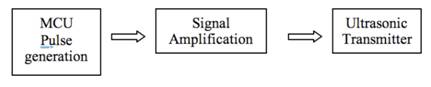
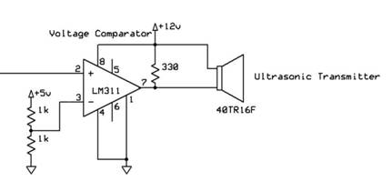
Figure 1. Transmitter Circuit
A
series of five short pulses blasted by the microcontroller only has 5V
amplitude, which will be attenuated down to less than 20 mV when received by
the receiver circuit. Hence, LM311
voltage comparator was used for signal amplification before transmitting the
signal. LM311 was used instead of
regular operational amplifier since it has faster switching speed. Low-to-high and high-to-low level output
response times were only 115ns and 165ns respectively, which was more than
enough for our application since the width of each pulse is 12.5us. The voltage comparator compares the 5V
input pulse generated by the MCU to 2.5V.
If the voltage level of the input pulse is greater than 2.5V it outputs
12V drawn from the power supply and drives the ultrasonic transducer, otherwise
it outputs zero. Hence the 5V input
pulses are amplified to 12V pulses.
The ultrasonic transducer converts its input voltage into sound waves
and emits them at 40kHz frequency.
Once
the transmitted wave hits an obstacle it’s reflected back and received by another
ultrasonic transducer that functions as a receiver.
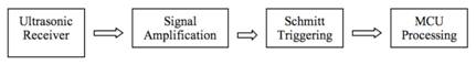
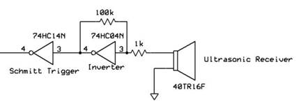
Figure 2. Receiver Circuit
First,
the ultrasonic transducer converts the received sound wave into voltage. The received signal was only about 50mV,
which means that it has to be amplified by a factor of 100 to get a 5V
signal. Hence, 74HC04N Hex Inverter
with 100kW/1kW resistor pair was used to achieve a gain of 100. The propagation delay of the inverter
was only 19ns, so switching speed was not of our concern. The inverted and amplified signal was
then inputted to a 74HC14N Schmitt Trigger to produce a clean square wave. Any value below the trigger voltage
(2.5V) gave logical zero (0V) and any value above 2.5V gave logical high (5V). Note that the inverted signal from the
inverter is inverted back by the Schmitt trigger. The output of the Schmitt trigger is
then fed into port B.1 for microcontroller processing and distance calculation.
|
|
|
|
Figure 3.
Array of LEDs |
Figure 4. Piezo speaker |


An
array of 6 LEDs and a piezo speaker is connected to portA and portB.3
respectively to warn the user of his or her proximity from the interfering
obstacle as we have discussed in High Level Design and Table 1.
Software Design
The
program was divided into four procedures:
1) interrupt
[TIM2_COMP] t2_compare(void)
The interrupt ran at 160 kHz. In order
to achieve this we used no prescalar on the clock and set OCR2 to 49. TCCR0 was set to compare on match. The
main functionality of the interrupt is to generate 5 pulses at 40 kHz. To do so we implemented a counter that
sets PORTB.0 toggling it every second pass through the interrupt. After five consecutive pulses have been
emitted we wait for the counter to reach 700 (4.375 ms). The waiting time is the equivalent of
sound traveling a distance of 1.49 m, which means that it gave us a range of
approximately 70 cm. In practice
this range could not be obtained.
Furthermore we decided on emitting a series of five short pulses instead
of one since it delivers more power.
We tested with a range of 1 to 8 pulses in a set of ping. The best results came from 5 pulses,
meaning that the received signal was stronger when 5 pulses are emitted.
2) void light_flashing(void)
Main function of this procedure is to
flash the LEDs. We determined that our upper and lower boundaries, that came to
be approximately 40cm and 15cm respectively. With this data we fragmented the range
into 6 distance intervals. When we
are receiving a pong we use the running average of the distance to determine
how far the object is. The closer
the object is to the transducers more LEDs will be lighted up.
3) void sound_gen(void)
This procedure generates a beeping sound
according to the distance of the object.
We used the same ranges as light_flashing( ) to achieve congruency
between the LEDs and the sound. We
used a function generator to produce sound with a sine wave and with a square
wave. Given the speaker we had available and the quality of sound it was able
to produce we decided to go for a square wave. Again using the function generator we
decided to run our wave at 4 kHz.
The way in which the procedure produces the sound is simply by setting
and clearing TCCR0. The speed at which we set and reset TCCR0 depends on the
proximity of the object, the closer it is the shorter we make the
intervals. TCCR0 is set to run on
Compare on match, with a prescalar of 256 and OCR0 set to 7. OC0 is toggled on
every match.
4) void main(void)
The main function begins by initializing
all the timers and counters, as well as any variable that needed to be
set. Within the while(1) loop we
only have to ‘if’ statements. The
first one reads PINB.1 to detect any pong. It also checks that all five pulses
have been emitted by checking that ‘count’ is beyond 40 cycles. We had to perform this check because
every time we emit pulses the receiver picks up some noise that could be read
as a pong by the MCU. If a real
pulse is detected then we immediately read the number of cycles that elapsed
from the first pulse until the pong was detected. Once we have this we perform the
appropriate operations to calculate the distance in cm. Since we are running the interrupt at
160 kHz this means that every cycle represents .2125 cm ((1/160000) Sec * 340
m/Sec). Multiplying the number of
cycles by this factor and dividing by 2 (to account for the distance to the
object and back) we calculate the actual distance. With this data we run a
running average of 7. We decided on obtaining an average because that way we
reduce any errors in our readings. We chose 7 by experimentation. We tried a
range of 5 – 20 running average calculations, but we observed that after 7 the
improvements in the calculations began to be insignificant. From within this ‘if’ statement we also
call sound_gen( ) and light_flashing( ), but we do this once the average for
that cycle has been calculated. The
other ‘if’ statement checks to see if more than 20 consecutive set of pulses
have been emitted without any response. If so it turns off any LEDs and sets
TCCR0 to zero (turns sound off). This amount of sets was determined by
experimentation as well. We tried different quantities starting at 6, but they
would be too fast. We scaled them by 2s until we got to 20 and got appropriate
results from the system.
Software Hurdles
Timers:
the hardest part to set was the timing scheme. The original idea was to
use Timer1 in fast PWM to create a 40 kHz signal that could drive the
transducers. We were also planning
on using Timer0 to run a clock from it. When we ran both interrupts nothing
would come from OC0, so we switched from Timer0 to Timer2 (which we eventually
kept using). This change did give
us results in OC2, but the interrupt from Timer1 would skip sometimes. We were
using Timer1 to keep the timers used to calculate the distance, but the
skipping made the data useless. To
solve this problem we decided to only use one interrupt, from Timer2, and used
it generate the 40 kHz pulses and keep our timer. As mentioned before we paid a price
since our timers could not be as fast as we would have liked.
Number of pulses in a set: there is somewhat random behavior in the
system that regards the number of pulses emitted in a set. Sometimes it is better to use 4 or 6, but
most of the times 5 give the best results.
This particular problem is hard to explain and can only be solved by
altering the code and setting the pulses to the optimum value (the one giving
best results for that particular instance)
Flashing of LEDs and sound frequency: We could not generate sound or flash the
LEDs within the interrupt. When we
tried, the whole system would simply stop working. We solved this by creating two
procedures, sound_gen( ) and light_flashing( ), that we called from main( ) and
that were completely independent of the interrupt. The consequences of these actions came
in instability in the flashing and the sound frequency. Our system sometimes flickers because
our soung and light functions are not called on regular intervals.
Missing pongs: sometimes we miss pongs because the
code does not go through the ‘if’ statement fast enough. This has two consequences:
a. Limits our range. Our minimum distance is limited by the
speed of our code. We tried keeping the code as short as possible to lower our
boundary.
b. Errors in distance
calculations: when we miss the wave from the first pulse we still read a
subsequent one. Since the timers
continue to run it created errors in our distance calculations, objects seem to
be farther away than they really are.
We fixed this problem by having the running average.
Testing/Results
The
resulting signal is shown below.
Channel 2 (bottom) shows the transmitted pulse that has amplitude of
12V. A single pulse in the picture
is actually a set of five short pulses.
Channel 1 (top) shows the received signal that has amplitude of 5V.
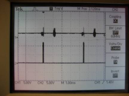
Figure 5. Transmitted signal (bottom) and received
signal on 1ms scale
A
ghost signal caused by the receiver directly picking up the transmitted signal
is also present on Channel 1. Since
the ghost signal is gated out when calculating the effective distance, it’s of
no significance in terms of our result.
The picture below shows the same signal on a smaller time scale.
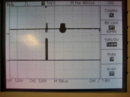
Figure 6. Transmitted signal (bottom) and received
signal on 500us scale
The
receive signal will be closer to the transmitted signal if the object is closer
to the device and vice versa.
Throughout
our circuit-testing phase we encountered countless noise issues and random
behaviors that compromised our result.
For instance, running a wire near the MCU caused spikes and flickers in
both the transmitted and received signal.
Orienting the whiteboard in certain direction sometimes caused random
noise and even gently squeezing a wire would throw off the signal. Since we are dealing with ultrasound, it
was imperative to reduce noise as much as possible to get a clean signal out
from the circuit and the MCU. On
the contrary to our prediction that the fan in the lab or other group’s
radio-frequency device would interfere with our circuit, they had no effect on
our circuit as far as the noise was concerned. We tried turning on and off the fan and
even asked couple neighboring group to turn off their motors or transmitters,
but that didn’t affect the quality of our output. The source of some of the random circuit
behaviors we encountered is still in question. Nonetheless, we managed to get a clean
signal from the receiver.
The
range of our device was approximately 40cm. As mentioned before, the effective range
is proportional to the power of the transmitted pulses. With 9V transmitting pulses we got a
range of about 34cm; 12V pulses gave us 40cm range and increasing the voltage
gave us slightly greater range. We
had to keep in mind that further amplification would result in more noise and
that we put more emphasis on accuracy than the range for our application.
To
test the accuracy of the device we measured the actual distance between the
sensors and the object with a ruler and compared that to the distance reading
we got from the LCD.
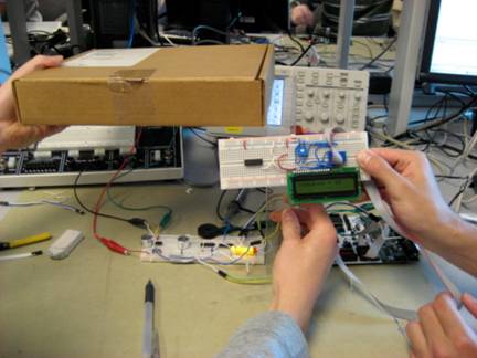
Figure 7.
Measuring distance between the box and the sensors with ruler and
ParKontroller
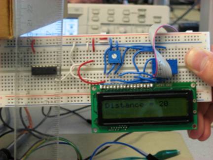
Figure 8. Actual distance of 20cm VS.
ParKontroller reading of 20cm
As
you can see from Figure 8, ParKontroller’s distance reading is very close to
the actual distance measured by the ruler.
Further testing showed that ParKontroller has an accuracy of ±1cm with one exception.
ParKontroller
emits ultrasounds at 40kHz, which is beyond what human ears can hear, so it
causes no harm to the public.
Furthermore, it can be used by anyone who can power on the device, watch
the LED indicators, or hear the warning beeps from the piezo speaker.
Conclusion
ParKontroller
can detect an object within a range of 40cm with accuracy of ±1cm in the distance interval of 15 to 40cm. If we were to do this project again, we
would try to increase the effective range and enhance the accuracy by
implementing some kind of noise reduction circuit. Furthermore, we would like
to implement an array of ultrasonic receiver so that we can determine the
location of the object with respect to the ultrasonic transmitter. Finally, usability of the ParKontroller
can be improved by making it completely portable and attachable to the bumper
of any commercial vehicles.
Intellectual Property Considerations
As
discussed in the High Level Design section, ParKontroller is a standalone
device that is designed using off-the-shelf parts and basic circuit design
principles; hence none of the copyright, patents, or intellectual property is
violated.
Ethical Considerations
1. To accept
responsibility in making decisions consistent with the safety, health and
welfare of the public, and to disclose promptly factors that might endanger the
public or the environment
Our
initial goal of this project was to create a parking sensor system with a range
of up to 1m with accuracy of ±1cm.
However, our resulting range was shorter with less accuracy. Had this been used by a daily driver it
may cause safety issues, but since our ParKontroller will not be commercialized
and distributed to public for use, it will not endanger the public or the
environment.
3. To be honest
and realistic in stating claims or estimates based on available data
All
results and data listed are shown and verified through multiple sets of tests
done in lab. It will also be
thoroughly demonstrated in lab during check out session.
5. To improve
the understanding of technology, its appropriate application, and potential
consequences
We
took a simple concept of SONAR technology and used our hardware and software
skills and intuition to create a useful application. Throughout the process of delivering the
final product, we gained much more than just understanding the technology and
its application. This hands-on
experience made us realize how other variables such as random noise, wire
capacitance, and temperature can affect the circuit and compromise the
result. These factors are often
ignored in theory-based classes where mostly ideal situation is
considered. We believe that it’s
important to learn and experience them to appreciate real-life engineering.
7. To seek,
accept, and offer honest criticism of technical work, to acknowledge and
correct errors, and to credit properly the contributions of others
We
tried to seek advice and help from
8. To treat
fairly all persons regardless of such factors as race, religion, gender,
disability, age, or national origin
The
ParKontroller can be used by persons of all race, religion, gender, age, and
origin. We also tried to
accommodate people with disabilities.
For instance, we designed an array of LEDs to indicate the proximity of
the object for people with hearing problems. We also implemented a speaker to emit
warning beeps for people with poor sights.
Regardless of these implementations, a small portion of the people
around the world would not necessarily be using this device if they are unable
to drive for various reasons.
10. To assist
colleagues and co-workers in their professional development and to support them
in following this code of ethics
Ethics
is taken seriously at this institution and is repeatedly mentioned and
encouraged at the beginning of each semester by many professors. As students, we follow this code of
ethics and try to remind it to friends and classmates whenever we see fit.
Appendix A: Program Listing
Source
code in C: ParKontroller.c
Appendix B: Schematics
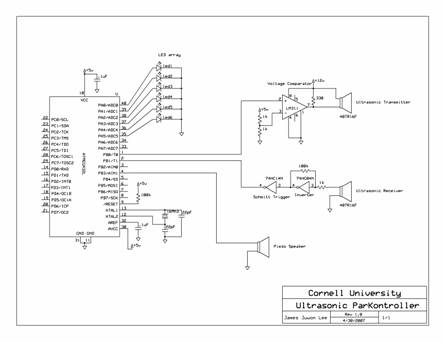
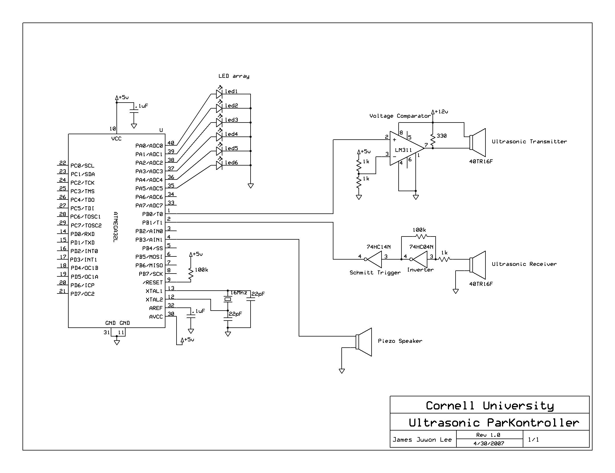
Figure 9. Complete schmatic of ParKontroller
circuit
ParKontroller_schematic
(enlarged version)
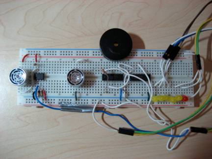
Figure 10. Final Circuit
Appendix C: Parts List
|
Parts |
Quantity |
Cost |
Notes |
|
Atmel Mega32 |
1 |
$8 |
|
|
STK500 |
1 |
$15 |
|
|
Whiteboard |
1 |
$6 |
|
|
Power Supply |
1 |
$5 |
|
|
Ultrasonic Transducer set |
1 |
$6.95 |
Jameco 40TR16F |
|
Hex Inverter |
1 |
$0.26 |
|
|
Hex Inverter Schmitt Trigger |
1 |
$0.24 |
|
|
LM311 |
1 |
$.50 |
From lab |
|
Piezo Speaker |
1 |
$1 |
From lab |
|
Total Budget |
$42.95 |
||
Appendix D: Team Contribution
James
was responsible for hardware design, construction, testing, and debugging. Mauricio was responsible for software
design, testing, and debugging. All
other tasks such as parts search and ordering, documentations, and webpage were
shared equally by both members of the group.
References
Handheld
Ultrasonic Rangefinder
Texas
Instrument LM311: Differential Comparator
Texas
Instrument 74HC04N: Hex Inverter
Texas
Instrument 74HC14N: Hex Schmitt-Trigger Inverter
Acknowledgements
We
would like to thank
Pictures
“Mauricio Tackling
CodeVision”
“James Testing
ParKontroller”