 |
|
the Newest Innovation in Patient Compliance
The Portable Programmable Medication Scheduler (PPMS) is a modern solution to the century old problem of patient compliance, featuring four medication bins, audio/visual alarms, a graphic LCD, and serial communication with a Java Swing PC GUI.
The conjunction of Electrical Engineering and the practice of Medicine has grown increasingly significant over the course of the past few decades, producing ever more innovative devices for the benefit of human healthcare. While biometric devices are often showcased in this arena, control devices such as ours are playing an increasingly substantial role as supplementary and autonomous caregivers. Providing a programmable medication scheduler forms an ever-present link between doctor and patient, capable of avoiding many common mishaps related to patient compliance.
|
|
| |
High-Level Design
Patient failure to adhere to medication protocols is an often overlooked yet tremendously signicant problem in medicine. Such compliance failures, due to forgetfulness or lack of information, result in missing dosages or taking medication incorrectly. Obviously, protocol mistakes like these have dangerous and potentially fatal consequences. A device capable of reminding patients which medication to take and when to take it could decrease the needlessly high rate of fatality due to non-compliance.
User Interface
The user perspective of the PPMS is intentionally simple, developed entirely with a target base of elderly and aging customers in mind. All scheduling complexity is hidden from the patient via the programmable serial interface maintained by a physician, family member, or perhaps the customer himself in some cases. The patient interacts only with two large push buttons and four pill bins, not unlike those used to manually manage medication. Under normal operating conditions, once the physician or other responsible person uploads a medication protocol the device becomes entirely autonomous until a schedule change is needed. Dosage reminders are announced by sounding an alarm and turning on an indicator light above the appropriate medication bin.
At this point the patient has the option of 'snoozing' the reminder for 5 minutes or opening the bin. While announcing the reminder, the medications contained by the bin are displayed by name, dosage amount, color and size on the screen (along with any additional neccessary information). The displayed information may be cycled through the use of either pushbutton. Once the corresponding bin is closed again the patient is ask whether he or she took the prescribed dosages. If not, a reminder announces the bin again in five minutes, otherwise an acknowledgement is displayed and the device returns to normal operation awaiting the next reminder time.
From the doctor's viewpoint, the PPMS is a simple computer peripheral capable of ensuring the proper scheduling of a patient's medication. The scheduling process takes place over a serial connection between the device and a PC. The programmer need only launch the scheduler application to begin interfacing. Medications are read in from a text library to avoid mispellings and redundant information. Each medication may be assigned to a particular bin with a certain time and amount, an interface entirely analogous to the device itself. Once the data entry is complete, clicking the download button will send the schedule to the device and immediately verify its integrity, informing the user of the encountered results. After a successful download the device is ready for normal autonomous operation.
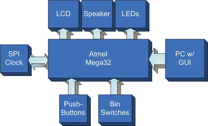
Hardware Structure Overview
We wanted the ability to display images as well as text to our users, so we opted for a graphical LCD, despite the added complexity. For screen size, we felt that 128x64 pixel resolution was suitable for the amount of texts and graphics we wished to display. A smaller screen could have been used, but at that point text would likely get hard to read.
One major limiting factor was that we opted to use a monochrome LCD rather than a color LCD. This decision was made based on our own lack of experience with programming LCDs in general, and because we were primarily using the LCD for text, and could still give medication color information in the form of text.
The next and more important decision with regards to LCD was selecting the LCD controller itself. The KS0108 controller by Samsung seemed very prevalent with LCDs of this screen resolution, and the documentation made it seem like a simple controller to interface with. Its instruction set was small, and it had no on-chip character generator, or multi-layered graphics capabilities. However, we also had no need for either missing feature as we planned to use large fonts and only simple bitmaps for graphics.
The major downside to this controller was that the documentation was occasionally ambiguous, and unofficial sources on using the KS0108 often conflicted with each other.
In addition to the LCD, we also opted to use an external real-time clock (RTC) for our device. As our scheduler is based entirely off a 24 hour clock, and we planned for our device to have its batteries changed more often than it was programmed, it was important that we retained an accurate clock through power outages to the main device. The solution was a RTC package that could be powered through a 3V coin battery, with a much longer battery life expectancy.
We opted to use SPI as the form of communication between microcontroller and RTC because a SPI send/receive function already existed in CodeVision AVR, which would save us time on coding. Unfortunately, the RTC models that used SPI communication had a great deal of functionality that we did not need to make use of, including interrupt generation, reset generation, the ability to set alarms, and tracking of time up to centuries. This added complexity ended up causing unnecessary complications during implementation. A simpler device would have probably been easier to work with. Also, SPI communication on the Mega32 is handled on the same pins as the programming pins � this again added complexity to our implementation as we had to protect our microcontroller from being programmed incorrectly.
Software Structure Overview
Software design for the device relied heavily on hardware constraints and abilities. Modularity kept code complexity to a minimum and allowed individuals to work independently. Thus the architecture features four components, the main scheduler code, the LCD library, the RTC library, and the Serial Interface library. Each component faced its own relevant tradeoffs but are designed to work together seemlessly despite any internal difficulties.
LCD and RTC libraries mainly focus on hardware-software interaction and therefore serve essentially as drivers for the use of the main scheduler. Their complexity is discussed more thoroughly in the hardware section.
Initial software decisions involved the development of a serial medication protocol which could easily transmit non-redundant, compressed schedule information between a PC and the device. A bare minimum number of transmissions are used in transfer schedules. This protocol is outlined below.
The most cumbersome software decision and implementation involved non-volatile memory management. In order to preserve a patient's schedule between power losses the EEPROM was chosen to store vital schedule information. However, the size of this memory resource is very limiting and required strict compression of schedule information. Likewise, EEPROM interaction is sparsely documented are required quite a bit of guess work managing pointers, reads, and writes.
Our main scheduler file required the greatest degree of tweaking to ensure potential customer satisfaction with the interface. The device is specifically design to act in ways one would expect with no particular or surprising behavior at any point. Prompts and displays required a high degree of readability not to mention intelligible wording for any event. Much thought and consideration comprises the current interfaces which do indeed work to our expectations.
Worth Noting
Products and patents similar to our prototype do exist. The company VRI has a medical alarm pill dispenser, which is designed as a large base station, and appears to only have a digital clock readout for a display. We have also found patent no. 5,347,453 (filed in 1994) which describes a programmable and compact integrated alarm and medication information display that would attach to pill containers or eye-drop dispensers, and display information regarding doses and special instructions. However, judging from the drawing, the display of the device is quite small (about the size of a medication label), and is made to attach to existing medication containers. We feel our proposed device would be a considerable improvement over these products.
Two standards are relevant to the device, SPI and USART communication for real time clock and PC interaction respectively. We also anticipate displaying time in the accepted fashion of HH:MM:SS. While this is beyond the scope of our project, it is worth mentioning that information entered into the patient mediation interface should conform to standards and information provided by the American Society of Health-System Pharmacists' Drug Information book, which includes information on label and off-label use for drugs, as well as drug interactions.
|
|
| |
Hardware Design
Pin Connections
| PORT.PIN | Connection |
| |
| A.5 - A.0 | LCD Interface Control Lines |
| A.7 | Pushbutton 2 Input |
| A.6 | unused |
| B.7 - B.4 | SPI Clock Interface |
| B.3 | Audio Output |
| B.2 - B.1 | LED Outputs |
| B.0 | Pushbutton 1 Input |
| C.7 - C.0 | LCD Interface Data Lines |
| D.7 - D.4 | Bin Switch Inputs |
| D.3 - D.2 | LED Outputs |
| D.1 | RS232 Serial Transmit |
| D.0 | RS232 Serial Receive |
|
LCD Operation
Power
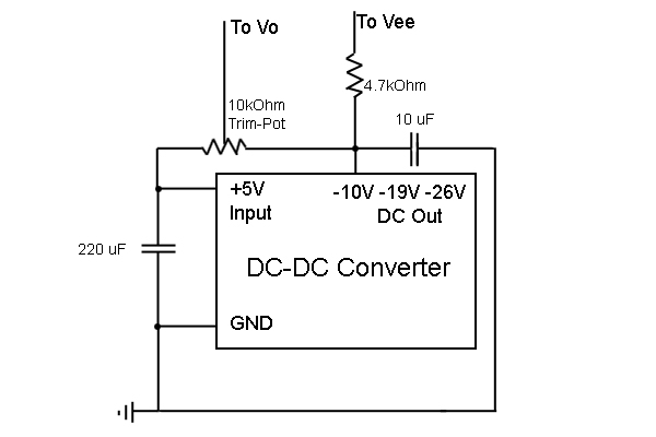
The LCD has 4 power connections: GND, +5V, -10V, and an adjustable voltage Vo for contrast adjust. The -10V power connection presented a problem for us because we only 0 and +5V to work with for power, and the LCD needed a relatively large voltage to display with good contrast. We solved this problem with a DC-DC converter from All Electronics, set up as shown below.
Originally we did not have the 4.7k load resistor in place, and found that the converter was drawing in excess of 200 mA of current. Adding the resistor reduce this to a much more acceptable 10-16 mA, which was within our power budget.
KS0108 Controller
The KS 0108 LCD controller is the component of the LCD that interacts with the microcontroller, and handles reads and writes to display memory. The controller features 8 data bits and 6 control bits that work as follows:
| | E | | enable � acts as the KS 0108 clock. Data and instructions are latched on the falling edge.
|
| D/I | | data/instruction � sets whether incoming byte is display data or an instruction
|
| R/W | | read/write
|
| CS1, CS2 | | chip selects for enabling each half of the screen
| CS2 CS1 | |
| 00 | Nothing Selected |
| 01 | Left Half Selected |
| 10 | Right Half Selected |
| 11 | - |
|
| RES | | reset � active low. Both screen halves turned off and deactivated. Display starts at 0,0.
|
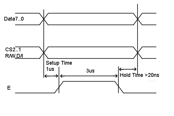
We did not need to read the display memory or status, so we only implemented sending instructions and writes. The write timing we were successful using is shown in the diagram below. It is important to note that the documentation for the KS0108 specifies only a 1 us cycle for E, whereas our implementation uses a 7 us cycle. We found it necessary to use a higher cycle time because of display errors that occurred with consecutive writes at the fastest timing.
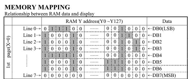
The screen coordinates 128 Y addresses horizontally, and 8 X addresses vertically (note: it is not our intention to confuse the reader with this reversed axis system, this is merely an attempt to be consistent with documentation). Bytes can be written vertically, top-down, at each Y,X coordinate pair, with a 1 representing a black pixel, and a 0 representing a white one. After each write, the Y address is automatically advanced by 1, so it is not necessary to constantly set the Y,X coordinates for a series of writes across the screen. Y and X addresses are specified each with their own commands. The Set Y Address command only uses a range of 0 to 63, so using the chip selects is important to make use of the full 128 pixels.
We made use of a modified Matlab script to encode bitmaps of characters and graphics into a .h file. The script traces through a bitmap as the KS0108 would display it, generating a pixel in the top down byte format. The script was originally used by Jason Amsel and Konstantin Klitenik in the HDD Clock project for ECE 476 in the Spring of 2006. We opted to use 10x16 pixel characters as a larger display font in case a user had poorer eyesight.
SPI Real Time Clock
The microcontroller accesses the RTC using the spi function included in CodeVision. The spi function simultaneously sends a byte and reads one, while controlling the SPI clock. After enabling the RTC with the chip select, the first byte it recieves sets a register address and whether or not it will be receiving information to write to that register, or if it is expected output the contents of that register. The byte encodes write/read in the MSB � a 1 in the MSB represents an incoming write to the address specified by the remaining 7 bits, and a 0 in the MSB represents a read requested from the specified address.
For a write, the RTC will store the next received byte in the specified register, so long as chip select remains active. For a read, the RTC will output the registers contents at the next spi function call, so the spi can essentially send garbage � only the clock and the received byte matter.
As far as setup and initialization, the RTC uses MSB-first, the CPOL and CPHA bits of the SPCR both set to one, and a clock rate of 2 MHz at most. When we were testing the RTC, we noticed it was fairly irregular with reads and writes at 2 MHz, and reduced the clock to 250 kHz. During integration, we found it was necessary to increase the clock rate to 1 Mhz to get it to read and write properly.
There are two bits in the RTC's registers that halt clock operations, and we found it necessary to always turn them off at initialization. They are the ST (stop) bit (bit 7 in the seconds register), and the HT (hold time) bit (bit 6 in the hourly alarm register).
As mentioned earlier, the SPI pins of the Mega32 are the same as its programming pins. To avoid errors in programming that could be caused by the SPI being connected while programming, we put 200 Ohm resistors in series with the serial clock, MISO, and MOSI wires. We found higher values of resistors caused errors in reads and writes, and that 200 Ohm resistors were sufficient to prevent programming problems.
Power to the RTC plays an important role in its operation. When the RTC loses +5V on its Vcc pin, it switches over to battery power to maintain the clock registers, and brings all input/output pins up to high impedance. Upon restoration of +5V, the pins will remain high impedance, with chip select disabled, for a variable length of time between 3-5ms. This meant that we had to wait and be sure the RTC was out of this state before trying to read from it again after turning power back on.
We should also note that the RTC documentation includes instructions on how to properly calibrate the clock for maximum accuracy. We did not calibrate for this project, but for long-term use this would probably be necessary.
Medication Bins
Although our original submission called for the use of small solenoids to control the opening and closing of bins, we instead opted to monitor to the open/close status of the bins through the use of switches. We found snap-action switches worked well for this because their lever arms could be pushed down by the lids without the switch being springy enough to prevent the lid from latching shut. Simple 3V LEDs were affixed to the back of each bin to be used as indicator lights for which bins should be opened.
|
|
| |
Software Design
Main Scheduler
The main scheduler is responsible for managing all libraries and most importantly the non-volatile medication schedule stored in EEPROM. This file contains the main method which initializes each library and then begins normal operation.
Schedule Structure
The schedule is compressed into a fairly simple structure described by the schedule.h header file. Each schedule contains an array of medications, a medication name heap, and the four bins corresponding to the schedule. Each medication contains information regarding its name pointer, color, shape, size, and any special information. Bins describe the physical bin containers on the device itself. Each one is associated with a specific time for the reminder to go off and any number of doses. A dose only contains a pointer to the appropriate medication and the an integer specify the quantity or amount of the medication should be taken.
Timing
The main while loop has several roles, one is maintaining the system time at an accurate rate. During each loop the current time is read from the RTC using the functions described below. This time is used to trigger special events such as turning off the LCD after a few minutes or announcing a reminder.
Bin States
Each of the four bins has a particular state associated with it, either empty or full. Full bins are considered to have medication within them. These states are used to trigger bin events in conjunction with the current time. Bin states are initialized when the device is turned on by checking the each bin time against the current time. Any bin with a time in the future is considered full and any bin with time in the past is considered empty.
Bin Events
For each pass through the main while loop the bin time for each bin in the schedule is checked against the current time supplied by the RTC as described. If the check indicates the bin is ready and the bin state happens to be full, the �bin_ready� function is called to handle the reminder routine.
Refill Events
After visiting the physician the device is of course full and ready for autonomous interaction. However, after a day of use the bins are emptied and in need of refilling. As such, when a bin with a bin state of empty is opened information is displayed which helps the user refill the bin appropriately. The display is exactly the same as that of reminders but does not involved the an alarm or message prompt afterwards.
Reminders
The �bin_ready� function, as mentioned, begins the reminder for a particular bin in the device. This reminder involves sounding an alarm and lighting the LED above the appropriate bin. The code then enters a while loop which checks that the bin has not yet been open or that the bin is currently open. During this loop information about the medication is displayed starting with the first dosage. The user has the option of increment the displayed dosage index by pressing either pushbutton allow for large fonts while still making all possible information readily available. At this stage the user can do one of two things: open and shut the bin or press both push buttons simultaneously. Pushing both causes an addition of five minutes to the snooze time for that particular bin which is taken into a count when the bin time is checked against the current time. Likewise a warning is displayed indicating the alarm will sound again. If the bin is opened and shut again the user is a prompted �Did you take the medication?� with a yes-no option (one for each pushbutton). Either of these events are detected through the ports defined above in the hardware section for each bin or button. If the user selects yes, a confirmation is displayed, otherwise the snooze time is again incremented as described. All these functions are handled within the while loop, constantly polling each button and bin for any possible changes and acting on those changes as necessary.
Audio Alarms
Sounding alarms is made simple in the main scheduler through the user of a timer interrupt which fluctuates port B.3 thereby producing a simple square wave at a low frequency. The fluctuations are enabled through the use a state variable indicating the current alarm state. When enabled the a millisecond counter governs the sequential playing of beeps by toggling yet another state variable. This sequence of beeps is audible enough for our expectations.
Warnings
As with any medical device, the PPMS includes its fair share of warning messages. When a bin opening is detected in the main while and the bin is known to be full a warning is displayed to the user in conjunction with sounding the alarm. If the bin is empty, refill information is displayed as described. Warnings are also displayed when snoozing a bin as this could lead to potential detrimental results and poor scheduling.
Serial Library
Serial Interfacing is taken care of entirely with the serial library implemented based on the built-in USART comm library for the Mega32. USART allows byte by byte download and upload schemes for the scheduler. The important functions for the serial library include �put_schedule,� �serial_init�, and �get_schedule.� Only serial_init is ever called directly from the main scheduler code. The get_schedule function is invoked upon receiving a serial interrupt indicating a potential schedule transfer or verification. The serial ISR calls get_schedule to begin interaction with the PC byte by byte according to the serial protocol described in the PDF file referenced by the appendix below. In summary, the schedule transmission is initialized, four bins are received, all medications described by a medication header are received, and finally all medication names matching the number of medications are received. Each bin may include several doses each with a reference to a certain medication index to avoid duplicate medication information. After receiving all this information, the temporary RAM copy is copied into the EEPROM for non-volatile use. The entire schedule is immediately retransmitted back to the PC for a quick verification and the transmission ends. The PC user is responsible for issuing a re-download for failed verifications. Aside from the interrupt and initialization the main scheduler has absolutely no interaction with the serial library.
More elaborately, the structure of the serial library is that of a simple state machine, switching between such states as BIN, DOSE, and MED while constantly reading in new strings to changes states or add data to the temporary RAM schedule model. Naturally, if an error is encountered during transmission the download is aborted and the temporary schedule discarded except in the case of a false verification as described in the previous paragraph.
LCD Library
The LCD library interface simplifies the main scheduler's code for drawing and writing characters to the LCD screen. Such functions as �string2LCD� allow any standard string to be written at a particular row and column of the display just as a character LCD would. Likewise, an implementation of the �drawShape� function allows the scheduler to display the shape of any given medication when necessary (such as during a reminder or refill).
RTC Library
Interaction through the real time clock takes places through SPI register interaction abstracted entirely by the RTC library discussed briefly in the hardware section. As a further level of abstraction, the main schedule implements two methods: get_time and set_time which allows the main scheduler to determine the current system time through a single function call and three variables for the current hour, minute, and second. The �set_clock� function is primarily used by the serial library when synchronizing the clock with the PC before each schedule download.
Java Swing GUI
By and large the Java GUI is immensely simple making use of the rxtx.org open source java serial library licensed under the GNU open license. This library mimics the former functionality of the javax.comm package, recently discontinued on Windows machines. The application is divided into the model, view, controller architecture. The model mimics that of the main scheduler with regard to schedule set up but in a slightly uncompressed fashion. The view is responsible for handling user events and interactions via a Swing interface. The control comprises the bulk of the application. After entering the information, the download button allows the user to transmit the schedule to the PPMS. Such communication is specified by the afore mention serial protocol, sending information byte-by-byte through the javax.comm standard interface over the RS232 connection. The code is heavily commented and available in the appendex.
|
|
| |
Results
LCD Screen
Our LCD was able to output images and strings correctly, with no visible flickering, even on nearly full screen re-draws. We were also able to implement sleeping of the LCD to save power. As a result of our inclusion of the DC-DC converter, the LCD drew more current than we initially anticipated. We were also unable to use the included LCD backlights because they required 450 mA of current, according to the documentation. Both the inability to use a backlight, and the unnecessary added complexity of the DC-DC converter could have been avoided by better LCD selection. We originally sampled such a device from Microtips USA, but the part was dead-on-arrival, and we had trouble getting them to send a replacement.
SPI RTC
The clock performed the functions we needed it for � keeping track of time even through loss of power from the 9V battery. Reading and writing for the RTC could probably be best described as quirky, but most issues were resolved by playing around with the SPI clock speed. We did not have any interference from the RTC while programming our final device.
Bins
The bin switches and LEDs worked well and consistently for our project.
Serial Interface
The serial interface was at times finiky but most problems were drawn from the medication protocol which required certain checks to ensure a synchronized transmission and verification. However, no major changes were made to the specified medication protocol from that described above. Although the terminal character was eventually changed to a tilda rather than a carriage return to avoid confusing it with the the corresponding integer value.
Scheduler Main
As mentioned the scheduler main required quite a bit of tweaking to draw out the appropriate user interface. However, its interaction with the libraries was excellently abstracted and allowed simple debugging as well as special additions to code and device functionality on a regular basis.
|
|
| |
Conclusions
While we had a more finished product in mind as the result of our project, we were successful in implementing a graphic LCD, a real time clock package, serial communication, and a PC GUI, and integrating them into a functioning system. We met our expectations with regards to individual component and overall functionality, and the resulting system works as a prototype for the device we intended to make. The GUI makes programming the device fairly simple through the use of the tabbed organization and simple pulldown menus, as well as the inclusion of a medication library. Once programmed, the device serves to offer a user reminders and information to help them adhere to medication protocol. We intended to make a device that served to assist a user, not restrict or control them, and we feel we've achieved that. Our device may also be patentable, and we would have to investigate existing patents further.
If we had a chance to do this project again, we'd benefit from being able to make more informed implementation choices and make better part selections as well � for example, a more carefully selected LCD with on board DC-DC and a lower power backlight would have given us the chance to add further functionality and spend less time on set up and testing of a single component.
A few things could have improved our project. First, a color LCD would have given us a bit more flexibility in terms of visual information that we could present to a user, so that would have been useful. 9V batteries tended not to last too long with our finished device also, so either the addition of a battery charger, or a focus on reducing power consumption would also add to the final result. Finally, if we had more time, we could probably improve significantly on our final packaging.
In terms of ethical considerations, we had to consider user safety first and foremost, as any failures of our device could have direct and dire consequences for the user. User safety was one driving factor in the decision to not lock the bins down in any way but rather monitor them using switches. We also were careful to be sure all wires were insulated, and to reduce the number of sharp edges on and solder spots on our boards. We also took note to see if any significant amount of heat was produced by the device, as that would also be a safety hazard. The use of an externally powered clock also adds to user safety by ensuring that time is correct even through drainage of 9V batteries.
We were honest in reporting all our part costs, including some that came later in the project, as well as in acknowledging those whose code we used.
This project served to advance our knowledge of technology and technical abilities a great deal, and we are open to criticism with regards to our results and implementation. Problems and potential hazards were always pointed out and discussed during the project.
Finally, we made considerations with regards to treating all potential users fairly, including the use of visual aids and larger fonts to make our device easier to use for the elderly.
|
|
| |
Appendix
Commented Code and References
Main Schedule C Code
Serial Library C Code
Real Time Clock Library C Code
LCD Library C Code
Java Serial Code
Mega32 Code Zip File
Java Gui Zip File
Medication Protocol
RTC Data Sheet
KS 0108 Data Sheet
DC-DC Converter Data Sheet
Java SE API
Schematics
All relevant schematics are shown above.
Cost Detail
| Vendor | Part | Cost($) |
| | |
| | Custom PC Board | 5.00 |
| | Atmel Mega32 | 8.00 |
| Maxim-IC | Max233CPP | sampled |
| | 6" Solder Board | 2.50 |
| Digikey | Pushbuttons | 2 x 0.94 |
| All Electronics | Mini Snap Action Switches | 4 x 1.00 |
| Digikey | STMicroelectronics M41T94 | 4.13 |
| All Electronics | DC-DC Converter | 0.50 |
| | LCD - AGM1264F | 9.95 |
| Digikey | 32.768 kHz Crystal | 0.28 |
| Digikey | 9V Battery Holder | 1.77 |
| Digikey | 9V Battery | 2.00 |
| Digikey | 3V Coin Battery Holder | 1.55 |
| Digikey | 3V Lithium Battery | 0.35 |
| | |
| Total | $41.91 |
|
Specific Tasks
Tim Schofield: hardware soldering and wiring for LCD, RTC, and protoboard, LCD Library, RTC library, DC-DC converter, integration and testing, character bitmap generation
Matt Caulfield: Java Swing GUI, Serial Library, main schedule library, software architecture, integration and testing, interface design, website design
|
|
|
|