Music Recognition Marionette
Dancing Pinocchio
The purpose of this project was to design a dancing puppet which is musically controlled by the microcontroller. This is a simple, inexpensive dancing puppet, which can dance to any tune you want. For as little money as possible, you can bring Pinocchio to life. Pinocchio can move, twist and dance to whatever tune is being played. With a smart efficient synchronizing system, two motors, and other electrical domains such as analog circuit design, we have created the most imaginable “Michael Jackson” puppet ever.
Music ŕ Digital Signal Processing (synchronizing) ŕ Motors ŕ Output to puppet
Fig. 1 - High Level Design of the “Dancing Pinnochio”
Rationale and Sources of Project Idea
This project was inspired from our one of our previous labs: Lab 2, where speech synthesis in the form of DDS was used to generate Cricket Calls according to arbitrary combinations of parameters entered by users. The need of dancing puppets in form of marionettes as toys for little kids was also another incentive. The previous project on the Musical Water Fountain [1], where the water responded to the musical beats was an ideal inspiration. We were interested in building a robot initially but we felt that it might be difficult to obtain the smoothness in the dance moves for the robot. This was mainly due to two reasons. First, the robot had to be imported from the Robotics laboratory, which meant we could not have access to it whenever we wanted and secondly, it was not completely balanced so it could not have leg movements. We had just a few weeks to build and manipulate a robot. Instead we came up with the idea of using a puppet as our object and making it dance to the beats! We found sample marionettes and similar projects from different comedic websites but they were all hand-controlled or beyond the scope of a semester long project. We figured we could make them motor-controlled and eliminate the use of hands controlling puppets to entertain loyal viewers. This was basically an idea to carry out a fun project for everyone i.e. the team members as well as other students and involved software, hardware and mechanical engineering basics.
Dance Moves
The puppet has two dance modes. One is a fast dance move triggered when a strong bass signal is detected. The other move is a slower and more constant move triggered when mid-range frequency signals are detected. Those signals include voice, guitar and piano tunes. The dance moves switches between those two modes automatically and live as the music changes.
The background math involves calculating the cut off frequency to sample the sounds at intervals which do not cause any aliasing of the signals. We decided to sample the incoming audio signal at 2kHz frequency which is conveniently located within the audible range of humans. To obtain this we had to compute the cut off frequency which is defined by the Nyquist Theorem which states that the highest frequency that can be accurately represented is given by twice the sampling frequency.
This was followed by implementing the hardware circuitry for the two-pole RC low-pass filters. This involved choosing the RC values such that
R*C = T
where T= Time constant.
Refer to figure 3 for the detailed values of the R's and C's that we used.
The cut off frequency of the analog filter is 1Khz
We also implemented a digital low pass filter in software. We found the coefficients in Matlab for the two-pole Butterworth Filter implemented digitally in the program. These were found to be
b(1) = 0.1410 b(2) = 0.2820 b(3) = 0.1410
a(1) = 1.0000 a(2) =-0.6940 a(3) = 0.2580
The Butterworth filter uses the following equation to low-pass filter out the signals.
b(1)*x(n)+b(2)*x(n-1)+b(3)*x(n-2) =
b(1)*x(n)+2*b(1)*x(n-1)+b(1)*x(n-2) =
b(1)* (x(n)+(x(n-1)<<1)+x(n-2))
where x(n) is the input signal at instant n;
x(n-1) is input value at instant n-1;
y(n) is the output value at instant n;
b(n) is the coefficient for the input values and
a(n) the coefficient for the output values.
For further details refer to the Math page [2] by Professor Bruce.
It was also needed to bias the input voltage to the ADC, so as to prevent the ADC from getting negative values and burning out. This was simply carried out using a voltage divider circuit with R values calculated as
I1R1 = I2R2 = Vcc/2 = 2.5V
R1 = R2 = 1M ohm.
Input Block
Different frequencies as a combination are provided from the musical device such as Ipod, laptop Winamp or an MP3 player as an input to the microcontroller unit, for carrying out mathematical computations like filtering and transformations into the time domain. These frequencies are then low-pass filtered using the RC circuit shown in fig. 3 and also biased to remove any negative voltage to the ADC in the microcontroller unit.
The same music is also fed to the speakers so that it is audible to humans and we can then see the puppet dance to the rhythm we hear.
Microcontroller Unit
The microcontroller unit is used for digitally filtering the signal after converting the analog signal from the device into a digital signal using an 8 bit analog-to-digital converter.
ADC
After the music signal is filtered by the RC low pass filter implemented in hardware, the resulting signal is fed into the ADC of the MCU. The analog to digital converter is set to capture music signals at a rate of 2kHZ. This sampling rate is chosen because the maximum signal that we want to capture is 1kHZ. Musical frequencies higher than that are not very useful for “dancing” purposes for the puppet.
The Analog to digital conversion is accurately timed using the Timer 0 compare interrupt. That interrupt service routine is set to fire every 0.5ms by setting the OCR0 to 125. The ADC conversion, carried out in ISR also gets executed every 0.5ms and hence samples the music signals at a frequency of 2kHZ. The accuracy and monitoring of the sampling frequency is very important because filters implemented in our project depend on that particular sampling frequency.
Signals entering the ADC on pin A0 of the STK500 are DC offset at 2.5V using a voltage divider. Therefore, the ADC values when no music is played is 127. Since the average amplitude of music signals being supplied is 1V. The ADC values will vary from about 80 to 170.
Output Blocks
The LEDs and Motors are placed at the output end of the system. This converted output from the microcontroller port pins is sent to the 2 LEDs corresponding to 2 motors.
One of the LEDs glows according to the bass of the music played and the other LEDs are made to glow as combinations of the beats heard. The LEDs are being used to confirm the accuracy of the output being fed to the motors.
Further, the 2 motors do receive the same input as the LEDs and are used for driving the limbs of the marionette. The legs are attached to one of the motors and the hands are attached to the other motor.
Finally, the marionette is in sync with the music being played, i.e. its movements follow the bass frequency and other beats continuously. Strings are used to attach to the motor which causes the movement of the limbs.
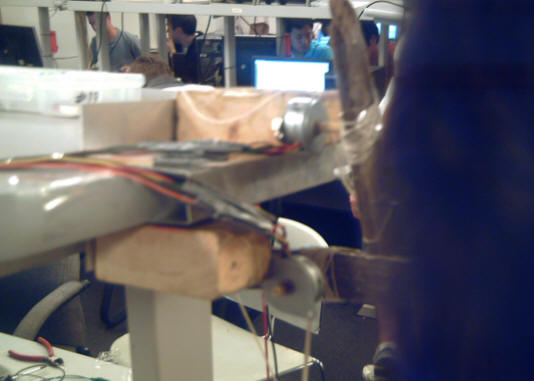
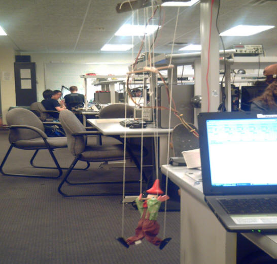
Our whole project was built on a clamp which can be attached to the side of a table or a smooth edge and two wooden planks were screwed to place the motors on. The motors were placed perpendicularly one above the other. A flat wooden piece was glued to one end of each of the motors. These were in the shape of a cross i.e. perpendicular to each other so that the rotary motion of the motor is converted to the swinging motion of the wooden pieces. Thus, moving the strings which were tied tightly to each end of the flat wooden piece, and to the wooden top of the dancing Pinocchio, which were connected to each pair of limbs.
Filters used
The software tradeoffs included using digital filters instead of the Walsh transform and therefore the sampling of the sound was different as we didn’t need the fast speed and sampling rate of the Walsh transform. This was mainly due to the fact that the faster the motor spins the more difficult it is to control the movement of the strings attached as that would be in the order of ms and the motion is visible only in terms of seconds. This made us realize that we could not use the Walsh Transform as though earlier and as used by the Musical Water Fountain project [1], so the tradeoffs were reasonably carried out. We used Butterworth filters instead.
Selection of Motors
We had to choose between a servo motor which offers a better control over the stepper motor which is inexpensive as compared to a servo. Given the limitations of our budget we decided to opt for the stepper motor which was bought for “Funny money”. Stepper motors offer a control and speed which is best suited for our purpose of controlling the marionette.
Motor speed vs. voltage (trading between voltages for motors) and vs. Microcontroller cycle time
While testing our motors and its response, we noticed that the Motor speed was affected by the voltage and microcontroller cycle time. When the motors were powered, more voltage went to one of the motors than the other, and when the microcontroller time was set at various counters, the full motor speed is not reached. We later came to the consensus that to reach our peak, after certain attempts, 9V power supply should be used to power the two motors at a counter rate of 10 for it to run as fast as possible and even out the power supply to each of the two motors.
Mechanical Tradeoffs
We also had a delay between the motor motion and string movement due to the parts used to connect the motors to the puppet. We used wood and strings that weren’t exactly rigid, which therefore caused a certain delay between the actual movement of the motor and the string movement of the marionette. These tradeoffs weren’t that hazardous to our project and what we wanted to accomplish but it did affect the time between the LEDs flashing the movement of the limbs of the puppet.
We believe that we did not have any standards regarding our project.
We do not have anything that has been copyrighted or patented by anyone to the best of our knowledge.
ADC – Filter
Interface
Each time the ISR fires, each ADC value is stored in an array: Abuffer. That buffer is of size 128. When that buffer is full, the ISR signals the higher hierarchy, that the buffer is full and filtering is ready to be done. This is done by setting the flag set_ready high.
Bass / Midrange Frequency Signal Detection
When such a high bass signal is detected, four actions are taken. LED5 is turned on, a flag motor_on is set to be used by the motor controller code, and timers t_motor and t_led are initialized to zero. Those are used to control how long the LED or the motor needs to be ON.
A different kind of puppet action/dance is desired when a mid-range strong signal is detected.
Such signals are, for example some voice
signals, guitars, pianos. For those signals, we want a slower dance move. The
puppet dance has two modes: A fast dance mode when bass signals are detected,
and a slow dance mode when mid-range frequencies are detected. The switching
between those two modes is done with a if else statement in the main while loop
and implemented with the help of a variable called
special. That variable is set when a
mid-range frequency signal is detected. To change the dance mode from fast to
slow when such a signal is detected, we change the timing of the motor, by
increasing the variable time_motor_on.
That makes the motor oscillate with smaller and more constant amplitudes,
producing a slow dance.
Motor Controller
Restricted by the physical setup of the motor and the marionette, a good dance move is achieved by rotating the motor forward and backward at a fixed frequency. To achieve that, an algorithm to switch the direction of rotation each time a strong signal is detected had to be implemented. Two variables motor_fwd and motor_back are constantly set to oscillate from one to zero, one always opposite to the other.
The distance of one rotation or the amplitude of the rotation is controlled by timing. This is done in the following way: As soon as a strong signal is detected, the timer t_motor is set to zero. That timer is incremented at a rate of one every 0.5ms in the timer 0 compare interrupt. When that timer has reached a desired set value, we turn the motors off and wait for the next strong signal detection. The higher that desired set value, the further the motor would have rotated. The motor values are set using a decimal value like 1+128 which represents a binary value of 10000001. This equals to the binary number when converted as mentioned before. Being a stepper motor we move it in four steps from 0 to 3.
Filtering
Two types of filters are implemented. One is a second order Butterworth low pass filter with cut off frequency of 100Hz. The other is a second order Butterworth high pass filter with cutoff of 400Hz. The latter filter can be interpreted as a bandpass filter with band 400Hz to 1000Hz because the signal is already low pass filtered in hardware with a cutoff of 1000Hz before being fed to the ADC.
The first low pass filter is implemented using Prof. Land’s assembly function IIR2() for Butterworth filters, thoroughly described in the math page. That function, being implemented with shifting instructions in assembly operates faster and with less instruction cycles than multiply functions in C.
Coefficients for that filter is obtained from matlab using the function
[b,a] = butter(2, 0.1)
This yielded the following filter coefficients:
b3= 0.1410
b2= 0.2820
b1= 0.1410
The second filter (high pass) is implemented using Prof. Land’s Butter2high() assembly function and the coefficients are obtained in the same way:
[b,a] = butter(2, 0.4)
The value 2 means a second order filter
0.4 is the normalized cut off frequency obtained from the following equation:
(2 * cut off frequency ) / sampling frequency = (2*400)/2000 = 0.4
The resulting parameters are:
b3= 0.3913
b2= -0.7827
b1= 0.3913
a3= 0.1958
a2= -0.3695
a1= 1.0000
Every time the Abuffer is full, main calls the function filter() that runs those two filters simultaneously.
The new buffer Abuffer_filtered
contains the result of low pass filtering
Abuffer
The new buffer Abuffer_filtered_high contains the result of high pass filtering Abuffer
The hardware design was basically split into two parts. The first part involved the basic RC Low pass filter and DC bias circuitry. This is shown in the following schematic diagram:
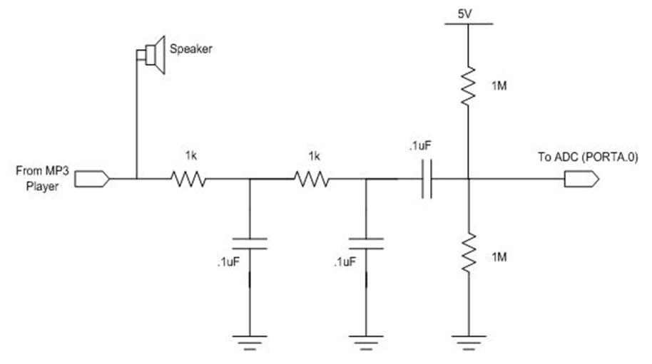
Fig. 3 – Low Pass RC Filter and Voltage Bias circuit
Here, the music is being fed from a source, namely the laptop’s music player Winamp. This can be replaced by any other music player, like, Ipod, MP3 etc. We initially used the Ipod for feeding the music for processing to the ADC, and shifted to playing music on the laptop due to the limitations of its battery power and plug sockets on the supply line.
The music from the player is fed via a 3.5mm stereo phone jack to the speakers and the ADC. The signal is divided into two cleverly, by connecting the speaker pins directly to the ground and the signal output of the phone jack with the help of banana clips. This is done so that we can “see” the puppet dance to the right beats. The musical signal from the source goes to the ADC and the speaker simultaneously.
Further, we needed a bias for the signal to be fed into the ADC because the player like MP3 or laptop provides an output at +/- 1.5 Volts. Giving a negative voltage to the ADC means killing it forever. Thus, we had to shift the level of this negative voltage such that the voltage varies from 0-5Volts suitable for the microcontroller unit. This has been done using the same voltage divider circuit as used in Lab 4 for the ADC. This is easily done using two 1Mohm resistors, one end of each resistor connected to each other and the other ends connected to GND and Vcc respectively. The common ends of the resistor are then connected to Pin A.0, i.e. ADC of the microcontroller unit. The voltage at this point is 2.5Volts due to the voltage divider circuit.
In Figure 3, a two-pole RC analog low- pass filter has been used to pass the lower frequencies, removing any high frequency. The resistor values were chosen as 1K each and capacitor values as 0.1uF to give a suitable time constant for the sampling frequency. At the current sampling rate of 2kHz, we are able to filter out the treble and input the typical music for decoding. We can accurately detect the highest frequency of 1kHz. Thus, filtering, removing treble and DC biasing the signal gives a processed and conditioned output from the source ready to be fed into the ADC.
Fig.4 - Motor Circuit
Fig. 4 represents the actual connections that were carried out (pictures taken in lab).
This is a simple circuit diagram and can be modified to incorporate the treble frequency for adding more variations to the frequency combinations for the marionette to dance on. Further, different RC combinations could be implemented to vary the Analog to Digitally converted values.
The second major hardware piece involved connecting the motors. We used two stepper motors for a better control over the dance movements of the puppet. This is the output side of our system. It consists of the two motor drivers to drive the two stepper motors rated 12 Volts each, a 9 Volt power supply and PORTC pins of the microcontroller. The pin and the wire connections of the motor have been represented in Table 1.
|
S.No. |
Wire Color of Motor |
Motor to ULN Pin No. |
ULN Pin No. to MCU |
PortC Pin no. |
|
1. |
M1 - Red |
- |
- |
- |
|
2. |
M1 - Green |
- |
- |
- |
|
3. |
M1 - Yellow |
10 |
4 |
13- C.7 |
|
4. |
M1 - Black |
11 |
5 |
2- C.6 |
|
5. |
M1 - Orange |
12 |
6 |
12- C.5 |
|
6. |
M1 - Brown |
13 |
7 |
3- C.4 |
|
7. |
M2 - Red |
- |
- |
|
|
8. |
M2 - Green |
- |
- |
|
|
9. |
M1 - Yellow |
10 |
4 |
11- C.3 |
|
10. |
M2 - Black |
11 |
5 |
4- C.2 |
|
11. |
M2 - Orange |
12 |
6 |
10- C.1 |
|
12. |
M2 - Brown |
13 |
7 |
5- C.0 |
Table 1
The control wires from the motors are connected to the Darlington array, which in turn are connected to the PORTC pins of the microcontroller. As the current drawn by both the motors is high we had to use a separate power supply isolated from that of the microcontroller unit so that the mega32 does not fry due to the excessive current drawn. The driver used for the motors was ULN2003AN. This is a pair of high-voltage, high-current Darlington array. Each stepper motor has six wires, two for supply and four for control as shown in Figure 5.
Figure 5 – Stepper Motor Configuration
The red and the green wires are connected to the positive supply of the power source for each of these motors as they are the center tapped wires. The rest of the four wires are connected in a phase. These were tested for a connection for short using the voltmeter. The two wires which were found to be connected belonged to the same phase and the other two were of the same phase. The phases are important while connecting the port pins because we are controlling these connections giving high bits from PORTC. The lower byte of PORTC is used for controlling the first stepper motor and the higher byte for the second. A motor test code was run to check the spin of the motor and its speed. This was slightly confusing because initially the motors were found to be vibrating only. They were not continuously moving in a single direction as desired, instead they were just “trying” to move. This was corrected by changing the wire positions to the input pins of the motor driver as advised by Professor Land.
After figuring out the appropriate connections to the appropriate wires and driver pins, we went on to set the appropriate speed for the motors. This is done by the software program which runs a set counter for the duration for which the motor should move. The lower the counter value, the higher the speed of the motor. Turning it to zero - the lowest possible value does not yield the highest speed! This simply stops the motor from running. Setting this counter value to the lowest possible value (it can take only octal values), it was found that the motors were not running at the same speed. This was due to the fact that the motors were not able to draw the same amount of current because the supply was set at 5 Volts only. Increasing the power supply for the motors to 9Volts, made them run at the same speed though still not maximum!
The motor circuit connections are shown in Figure below.
It is
difficult to position it accurately using the usual DC motors (other than
stepper or servo). Even if the timing is right for starting and stopping the
motor, the armature does not stop immediately. DC motors have a very gradual
acceleration and deceleration curves; stabilization is slow. Adding gearing to
the motor helps to reduce this problem, but overshoot is still present and
throws off the anticipated stop position. The only way to effectively use a DC
motor for precise positioning is to use a servo. These are complex and
expensive to implement. Thus, we used a stepper motor which does not provide a
very accurate control but does provide a good control suitable for our purposes.
Stepper motors behave differently than standard DC motors. First of all, they
cannot run freely by themselves. Stepper motors do as their name suggests --
they "step" a little bit at a time. Stepper motors also differ from DC motors in
their torque-speed relationship. DC motors generally are not very good at
producing high torque at low speeds, without the aid of a gearing mechanism.
Stepper motors, on the other hand, work in the opposite manner. They produce the
highest torque at low speeds. Stepper motors also have another
characteristic, holding torque, which is not present in DC motors.
Holding torque allows a stepper motor to hold its position firmly when not
turning. This is useful for applications where the motor may be starting and
stopping, while the force acting against the motor remains present. This
eliminates the need for a mechanical brake mechanism. Steppers don't simply
respond to a clock signal, they have several windings which need to be energized
in the correct sequence before the motor's shaft will rotate. Reversing the
order of the sequence will cause the motor to rotate the other way. If the
control signals are not sent in the correct order, the motor will not turn
properly. It may simply buzz and not move, or it may actually turn, but in a
rough or jerky manner.
Our motor runs at a suitable speed fast enough to make the puppet dance. The power supply was set to 9v, so that the two motors will be powered at almost equal speed and enables the puppet to dance to the beat of the music. The LEDs also flash accordingly to the beats of the music accurately. A slight delay occurs between the motors and puppet due to the parts used – wood and string. Otherwise, the puppet dances precisely to the beats of the music to the naked eye.
To test the accuracy of our digital filters, we used matlab for our coefficients of the Butterworth filters, and the oscilloscope was used to measure the components of the signals and the corresponding LED flash on the STK500 are displayed according to a certain threshold. We did notice the slight delay when the LEDs did flash and the beat heard, but it wasn’t that critical, and our puppet did dance. The puppet does move its limbs to the beat and makes extreme movements at the bases, and it goes accordingly to the tunes coming out of the speakers, as expected.
This wasn’t that much of a concern for us at the end product. We made sure during our developing phase; the puppet which was made out of cloth wasn’t put close to the circuits or wires that do have power supply through them and could cause fire or sparks. Also we made sure the wood used was cut and the space was cleaned the woodshop. We also make sure we wore closed-toe shoes will doing so. We checked our motors constantly to make sure if weren’t overheating. We did not solder any boards.
Our project can be used by anyone. All it needs is its power supply and some music and the puppet will operate accordingly. Although for this class, our project wasn’t exactly make to be sold in stores. Therefore, it could be used for demo purposes only. However, we think this is a great entrepreneurial idea to dive into.
Our expectations were somewhat met. Although we didn’t get Pinocchio to dance just like Michael Jackson, we got it to move to the music played consequently and swiftly. We accomplished controlling the puppet with our efficient synchronizing system, motors, and other electrical domains. Overall, we learned a lot and put a lot of effort into this project and the class in general was very meaningful and helpful to us. We accomplished the task of making an efficient and exciting Dancing Marionette!
- IEEE ethics
We made sure we followed the IEEE Code of Ethics throughout this project.
- To be consistent with the safety, health and welfare of the public. To disclose promptly factors that might endanger the public or the environment.
Given that our puppet was made out of cloth and the motors were powered, we took very careful concern on safety and health issues. We made sure the electronics and wires were not in contact with the cloth which is a flammable object. We make sure all group members and everyone surrounding our project were aware of the risks associated with it, and were extremely careful when standing near our project during the actual presentation.
- To avoid injuring others, their property, reputation, or employment by false or malicious action.
We made no false accounts or accusations of any kind, and we were not rude to anyone during this project. We had no legal issues.
- To make ensure the power limits of the motors and chips stay within certain level.
We made sure we set the power level to a certain amount (9v) so that the motors don’t overheat and burn during or after the tests.
- To design a system which would not have any sharp ends and nails so a user or surrounding people using the object don’t get hurt.
We had no work unattended to, and we made sure the wood and nails used were cleaned and disposed of after building our stand. We also wore closed toe shoes in the woodshop while making the stand.
- To give credit to the contributors and group members of the project.
All our members were thanked and rewarded accordingly.
- To maintain and improve our technical competence and to undertake technological tasks for others only if qualified by training or experience, or after full disclosure of pertinent limitations.
Due to the slightly dangerous nature of our project, safety was always a concern. We made sure we bored we didn’t leave any power supply on while fidgeting with the puppet, and asked professionals or our mechanical engineering friends to cut wood that we couldn’t handle.
- To improve the understanding of technology, its appropriate application, and potential consequences.
We specifically chose this project despite a lack of knowledge in certain areas. Using the internet, expert resources, and professionals, we learned everything we needed to know, and sometimes even applied the knowledge in a different way to complete our project. We purposefully stepped out of our comfort zone in order to complete this project.
- To treat fairly all persons regardless of such factors as race, religion, gender, disability, age, or national origin.
We are a well rounded group and extremely multi racial.
Final code.c - Code for the puppet
Motor test code.c
- Code for the Motor
|
Parts |
Cost |
|
2 Breadboards |
$12.00 |
|
2 ULN2003AN |
Sample |
|
2 Stepper Motors |
$2.00 |
|
DIP socket |
$0.50 |
|
STK 500 |
$15.00 |
|
Mega32 |
$8.00 |
|
Wood & Nails |
Stolen/Free |
|
Power Supply |
$5.00 |
|
Puppet – Beth’s closet |
Free |
|
Clamp – Courtesy of Prof. Land |
Free |
|
Rope |
Stolen/Free |
|
Glue – found in lab |
Free |
|
Wires – found in lab |
Free |
|
Total |
$42.50 |
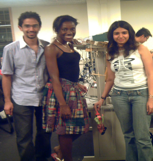
We all worked and supported each other during this project. We fought, cried, and laughed our way through this process. It was a truly a team work, however, the major tasks below were assigned to each member of the group to make sure it was done thoroughly.
Overall lab work participation – ALL
Report - ALL
Circuits; website - Pallavi
Debugging code - Stephane
Building puppet and stand; parts; website - Beth

Websites
Datasheets
We would like to thank Professor Land and the TAs especially Eric Okawa for all of their help. Thanks to our fellow lab partners for tolerating us throughout this project and becoming good friends at the end.
We would also like to thank Texas Instruments for shipping us free samples of motor drivers.