ECE 476 Final Project:
Automated Pet Feeder
Chong
Siew Jun Cindy (sc433) and Marvin HD Mao (mhm42)


Left:
Junior ECE Marvin Mao demonstrates a heightened level of alacrity and awareness
in the lab. Right: Senior ECE Cindy Chong: “Why the dispenser don’t want to turn???.”
Our project is an automated pet feeder that is controlled by
a wireless infra-red remote control.
As pet lovers, we understand that the responsibilities of
life sometimes inhibit pet owners from properly caring for their pets. Pet care
should be fun, not burdensome, and so our goal with this project was to assist
owners with pet care by providing a system that automates diet management.
Our pet feeder consists of two components. The first
component is a remote control that allows pet owners to design the diet plan
for their pet. The second component is a feeder that receives instruction from
the remote control and refills the pet bowl (to feed the pet) when appropriate.
Wireless communication is achieved via IR transmission. The overall program flow is illustrated in
Figure 0.
Figure
0:
Logic flowchart for our project. The remote component automates the feeder
through IR transmission.
The user interface on the remote consists of a keypad and
LCD. The LCD prompts the options the user can select and the keypad allows the
user to make a selection and input data. The feeder consists of a
motor-controlled food dispenser (where a high torque DC motor is used to turn a
wheel in the cereal dispenser) and three weight sensors to monitor the weight
of food in the pet bowl. The user interface and the feeder communicate via a
pair of IR transceivers and IR endecs (encoder and
decoder).
There were two aspects of our project where
hardware/software tradeoffs were considered. The first involved the
transmission of IR data between the remote and feeder components. Data is
transmitted using the IrDA standard, so IR endecs
were used to handle the translation from RS-232 to IrDA. Although the signals
could be translated in software, handling the translation in hardware allowed
us more time to focus on other issues in our project. The second aspect
involved low-passing the signals provided by the weight sensors measuring the
weight in the pet bowl. Voltage spikes caused by adding to or removing food
from the bowl needed to be filtered, and instead of building a low pass filter
in hardware, an averaging function was implemented in software. Since surface
stability is essential to accurate weight measurements, the reduction in
hardware allowed us to construct a more accurate weight sensor circuit.
RS-232 and IrDA (Infrared Data Association) standards were used
in this project. RS-232 was used to communicate between the Mega32 chip and the
IR endecs. IrDA was used to communicate between the
IR transceivers and between the transceivers and the endecs.
There were no patents or copyrights associated with this project.
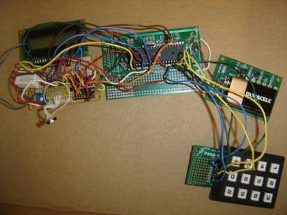
Two Mega32’s were used to run the two components of this
project. The Mega32 on the remote component was responsible for handling the
user interface and informing the feeder component when to refill the pet bowl.
The Mega32 on the feeder component upon receiving instruction to refill the
bowl would activate the motor-controlled food dispenser until the bowl was
filled up.
Remote Component
Three functions were programmed into the remote. The user can change the remote’s current
time, input a new feeding schedule and prompt the feeder to refill the pet
bowl. The state diagram used to handle these functions is shown in Figure 1.
The method for handling keypad debouncing was reused
from Lab 2.

Figure
1:
State diagrams for the LCD/keypad user interface. The three available options
are change time of day, input feeding schedule and refill bowl. The third
option is also executed if the current time matches a feeding schedule time.
The setup used to interpret the keypad input is a modified
version of the sample code given in Lab 2 tailored for the scavenged keypad we
used. Pins corresponding to the rows and columns were separately read in order
to determine which key was pressed, and the numeric value of the key pressed
was stored in a variable for use in other functions. Figure 2 displays how we
wired up the keypad.
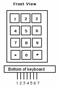 Connection on bottom
Pin 1 -- Column 1: 1 4 7 *Pin 2 -- Column 2: 2 5 8 0Pin 3 -- Column 3: 3 6 9 #Pin 4 -- Row 1: 1 2 3 Pin 5 -- Row 2: 4 5 6 Pin 6 -- Row 3: 7 8 9Pin 7 -- Row 4: * 0 #(a) Each switch shorts one row to one column.(b) Each pin should be connected to one bit of an i/o port.(c) The i/o port pins will be used both as inputs and outputs. When they are inputs, they have internal pullup resistors turned on.
Figure 2: A pin
layout of the keypad used and a short description of how the keypad input was
interpreted.
The connection of the LCD to PORTC is detailed below. A trimpot was used to adjust contrast.
[LCD] [Mega32 pin] 1 GND - GND 2 +5V - VCC 3 VLC 10k trimpot wiper (trimpot ends go to +5 and gnd) 4 RS - PC0 5 RD - PC1 6 EN - PC2 11 D4 - PC4 12 D5 - PC5 13 D6 - PC6
14 D7 - PC7
Accurate timing is critical to automating the feeder to
dispense food according to the inputted feeding schedule. Timer0 was set to a 62.5kHz
PWM signal for IR transmission, so to implement an accurate
1ms timing scheme a counting variable that alternated between 62 and 63
(average 62.5) was used. Additional timing variables to count seconds, minutes
and hours were directly modified in the timer0 overflow ISR.
Another important design consideration was to have the
remote control capable of automating the feeder upon a reset. To accomplish
this, the remote’s current time and the current feeding schedule are stored in
EEPROM and copied back into volatile memory upon reset. However, the timing
will not be updated when the remote is turned off. Implementing a device that
will track timing even when the remote is turned off is beyond the scope of our
current project.
The design for IR communication was based
off of a previous 476 project Wireless
Electromyograph. A string of ones is transmitted for
one minute to indicate that the bowl should be refilled. This signal is
outputted as a RS-232 UART through port D.0. A MCP2120 IR encoder converts the
RS 232 signal to the IrDA standard. The signal is then transmitted via IR
transmission by a transceiver, and is received by another transceiver on the
receiving end. A MCP2120 IR decoder then converts the IrDA standard signal back
to a RS 232 signal. This is illustrated in the following Figure 3.
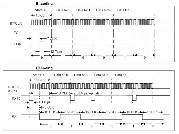
Figure 3: Diagram illustrating the encoding and decoding of signals using the IrDA standard.
To ensure reliable communication, the baud rates of the
Mega32 UART and the MCP2120 must match. A 62.5kHz
square wave produced by the Mega32’s timer0 was used to drive the MCP2120. By
hardwiring the BAUD2:BAUD0 pins of the MCP2120 to 100, the clock divider of the
MCP2120 is set to 64 and the effective baud rate for the endec
was:
![]()
To have the MCU match this baud rate, UBBR was set to:
![]()
More specifically, UBBRL was set to 0xff and UBBRH was set
to 0x03.
The IrDA compatible signal was transmitted using a ZHX1810
IrDA transceiver. The device receives 0-5V CMOS compatible signals and contains
an IR diode with rise time and optical transmission spectrum that adheres to
the IrDA standard. The standard also requires
reliable transmission of at least 1 meter, which our circuit meets. The IR
transmit circuit is shown in Figure 4.
Figure
4:
IR transmit circuit. A RS-232 UART signal is outputted
out of port D.0, converted to IrDA standard in the MCP2120 and transmitted with
the ZHX1810 (shown by purple line). The MCP2120 is driven by a 62.5kHz square wave (shown by green line).
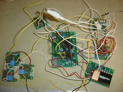
Feeder Component
Three concurrent tasks are run on the feeder component MCU:
monitor the weight of the pet bowl, receive instruction from the remote
control, and activate motor controlling the dispenser under correct conditions
(reception of instruction to feed and an empty pet bowl).
The weight of the pet bowl is measured using two IESP12’s,
push button force sensors. (A third sensor was included for testing purposes
but was not used in the computation of the weight of food). The sensors act as
variable resistors that are sensitive to the weight or pressure on top of the
push button. To translate this into a voltage that the MCU can read, the
voltage divider circuit in figure 5 was used.
Figure 5: Voltage divider circuit used to determine the weight of the food bowl.
The selection of 1MΩ resistors was to maximize the
change in voltage with respect to a change in resistance for the variable force
sensor resistor. Figure 6 displays the sensor resistance as a function of
weight (gf = force created by a mass of 1 gram). When
no weight is present, the sensor resistance will be greater than 100MΩ
and the voltage divider will read:
![]()
We anticipated an applied force of 500gf when the bowl is
full, which implies the sensor resistance is around 10kΩ and the voltage
divider output equal to:
![]()
Thus, with this selection of resistors we were able to utilize
the full 0-5V range.
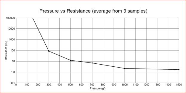
Figure
6:
Pressure vs. Resistance graph for the IESP12 taken from the IESP12 datasheet
courtesy of CUI Inc. We anticipated a maximum weight of 500gf which corresponds
to a resistance of 10kΩ.
The following snippet of code was used to calculate the
weight of the food bowl.
if (ADCSR.6 == 0)
begin
if ((Aindex%2)==0) ADMUX = 0b11000000;
if ((Aindex%2)==1) ADMUX = 0b11000001;
Ain = ADCL;
Ain += ADCH*256;
sum+=Ain;
Aindex++;
if (Aindex==200)
begin
Aindex=0;
weight = (int)(sum/200);
sum=0;
The output of the three voltage dividers
were fed into port A.0, and A.1, which corresponded to the ADC input 0 and
1 respectively. To maximize the accuracy of the A/D conversion, ADCSR was set
to 0b11000111 so that the ADC clock frequency was minimized and all 10 bits of
the data register utilized. Each ADC channel was sampled sequentially and the
weight was calculated to be the average of 200 samples, 100 per channel. The
averaging reduces the effect of any voltage spikes caused by weight changes in
the food bowl.
When the weight is calculated, the average samples ADC value
is compared to an upper and lower weight threshold. The upper threshold of the
average sampled ADC value was chosen to be 999 and the lower threshold was
chosen to be 850. The use of two thresholds instead of one threshold acted as a
Schmidt Trigger implemented in software and reduced unwanted spikes in the
determination of whether the weight of food in the bowl was sufficient. Due to
the wiring of the force sensor in series with a 1Mohm resistor, the greater the
weight of food, the smaller the resistance of the force sensor, and thus the
smaller the voltage drop across the force sensor, and the smaller the ADC
sampled value at Port A.0 and A,1. The ADC sampled values thus decrease as the
weight of food increases. A refill bowl instruction is executed if the average
ADC sampled value is above the upper threshold (i.e. insufficient weight of
food), and is ignored if the weight is below the lower threshold. In addition,
a green LED is lighted if the bowl can be refilled (i.e. insufficient weight of
food), and a red LED lighted if the bowl should not be refilled.
The IR receive circuit, as shown in
figure 7, is essentially the same as the IR transmit circuit in the feeder
component. An important difference, as noted in the Wireless
Electromyograph webpage, is that the Tx pin of the MCP2120 must be tied
high when receiving IR signals, whereas the Rx pin can be left floating when
the device is transmitting IR signals. This is to inhibit the transmit function
when receiving signals since the MCP2120 gives priority to transmission and a
floating Tx pin may accidentally induce a transmit
instruction, when it is supposed to be receiving signals.
Figure 7: IR receive circuit. An IR signal is received by the ZHX1810, converted to a RS-232 UART signal in the MCP2120 and inputted into port D.1 (shown by purple line). The MCP2120 is driven by a 62.5kHz square wave (shown by green line).
A refill bowl instruction is executed when five 0xff bytes
are read in succession. At this point, a PWM signal is fed into PORTC.0 of
figure 8 below. Through testing, the current frequency and duty cycle setting
of the PWM signal was found to minimize the chances of jamming in the food
dispenser. The motor is turned off when the weight of the bowl crosses the
lower threshold, signified by the red LED turning on. The optoisolator
isolating circuit for the DC motor shown in figure 8 was adapted from Lab 5.
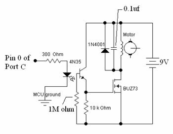

Figure
8:
Optoisolator circuit used to drive the motor. A 9V
battery was used on the motor end.
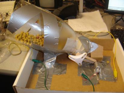
Food Dispenser
A cereal dispenser was used to contain the pet food. The
wheel in the cereal dispenser was connected to a high torque DC motor via a
thick rubber band so that when the motor was turned on, the wheel was turned
and the food would be dispensed. Initially, we had a lot of difficulty getting
the wheel to turn as there was too much friction and the pet food was too
heavy. The torque provided by the DC motor was insufficient in turning the
wheel. Friction was minimized by cutting down the flaps of the wheel which
reduced the contact between the wheel and the sides of the cereal dispenser.
The cereal dispenser was also tilted at an angle to reduce the weight of the pet
food on the wheel. The motor and cereal dispenser was then taped down into
position using duct tape and a box to hold the cereal dispenser in position.
With this setup we were able to dispense food with minimal jamming.
Force Sensor
The system to measure the weight of the pet food comprised
of two force sensors that were placed under the food bowl. The sensors were
soldered onto tiny solder boards that were then held together using duct tape.
The final result of our project design accomplished the main
goal of designing an automated pet feeder. The remote component was able to
acquire and implement a feeding schedule and the feeder component was able to
refill the pet bowl at appropriate times and to the appropriate amount.
Speed of Execution
Since feeding times were accurate to the minute, speed of
execution was not an issue since the process of refilling the pet bowl at a
specified time could be completed within a minute. More specifically, the IR
transmission of the refill bowl instruction and the subsequent refilling of the
pet bowl took less than minute. In addition, the weight of the bowl was updated
at a much greater frequency than one reading per minute.
Accuracy
The final design was able to meet the accuracy requirements
as set in our project expectations. By updating timing variables in the ISR,
timing was accurate to the minute. Combined with our method of coding a refill
bowl instruction as a string of ones sent over a minute, this setup ensured
that the pet bowl was refilled at the correct time. In addition, our design of
the force sensor circuit and calibration of the MCU’s
ADC allowed us to efficiently determine whether the pet bowl was full and
ensure that the dispenser did not add food when the weight of food was already
sufficient.
Usability
The usability of our project as an actual pet feeder is
inhibited by the limitations of our mechanical design. Realistically, the
feeding component of our device would be susceptible to a rowdy pet who tried
tampering with it. However, with the current set-up using duct tape and
cardboard boxes, the structure of the pet feeder is not ideal and could be made
more stable with better materials.
However, from a user point of view our project is simple to
use. The user interface on the remote is instinctive and easy to navigate.
Storing schedule and timing information into EEPROM also makes the design very
robust. All that is lacking is a timing device that is active even when the
remote is turned off.
Safety and Interference
Safety was not a concern in our project since all components
excluding the MCU and motor ran on 5V. Also, there were no heavy objects in our
design or direct connections to the human or pet body. Interference was also
not an issue since our IR signals were transmitted over a very small distance.
Also, not many other groups were using IR.
Our project succeeded in meeting the goals that defined our
automated pet feeder. By entering a food schedule and time of day into the
remote, the device was able to automate the feeding of the pet by instructing the
feeding component to refill the pet bowl at the scheduled times. The feeding
component also ensured that the contents of the bowl did not overflow,
especially if the bowl was already full during a scheduled feeding time.
While our main goal was accomplished, there are features
that could be added to this project. Originally we wanted the feeder component
to be able to operate independently of the remote. This required that when a
feeding schedule or time of day was inputted into the remote, this data would
be transmitted to the feeder component via infra red transmission. In addition
we hoped to let the user determine the amount per feeding for each feeding
time. Both features could not be included because our IR transmission was not
accurate enough. We contacted Arthur Gariety, one of
the creators of the Wireless
Electromyograph project and have come to the
conclusion that the source of the noise experienced in our transmission most
likely derives from the clock circuit used to drive the IR endecs.
That group was able to scavenge a clock oscillator circuit of a much higher
frequency and thus was able to use a much higher baud rate for data
transmission.
Also, given more time (and perhaps better expertise), we
hope to design a better dispensing system that is less prone to jamming and
physically more sturdy. The use of a more powerful motor or solenoid could
accomplish the former, though acquisition of such a device would send us way
over budget.
The design conformed to RS-232 and IrDA standards. All
reused code and design was implemented with permission. There were no legal or
intellectual property considerations to worry about.
Ethics
We adhered to the IEEE Code of Ethics throughout this
project:
1.
to accept responsibility
in making decisions consistent with the safety, health and welfare of the
public, and to disclose promptly factors that might endanger the public or the
environment;
We ensured we remained under
the power limit of our devices and that none of them got too hot during
operation. We also isolated any sharp objects that could potentially hurt
others.
2. to avoid real or
perceived conflicts of interest whenever possible, and to disclose them to
affected parties when they do exist;
We did not hog resources such
as workstations or soldering stations.
3. to be honest and
realistic in stating claims or estimates based on available data;
We were honest in our report
and made realistic claims towards what our project is capable of performing.
4. to reject bribery in
all its forms;
The only monetary transactions
involved buying ourselves snacks and drinks to cheer ourselves up.
5. to improve the
understanding of technology, its appropriate application, and potential
consequences;
We committed ourselves to
learning how microcontroller design could benefit the pet industry.
6. to maintain and
improve our technical competence and to undertake technological tasks for
others only if qualified by training or experience, or after full disclosure of
pertinent limitations;
We learned a great deal about
wireless IR transmission and motor mechanical systems such as stepper motors
and servo motors, which we experimented with but did not use in the final design.
7. to seek, accept, and
offer honest criticism of technical work, to acknowledge and correct errors,
and to credit properly the contributions of others;
We were open to advice provided
by our peers, TA’s and
8. to treat fairly all
persons regardless of such factors as race, religion, gender, disability, age,
or national origin;
We did not discriminate at all.
9. to avoid injuring
others, their property, reputation, or employment by false or malicious action;
We did not commit to vandalism
or any violent acts.
10. to
assist colleagues and co-workers in their professional development and to
support them in following this code of ethics.
We gave assistance when we felt
qualified to help.
Remote component code
#include <mega32.h>
#include <stdio.h>
#include <delay.h>
#define t1 30
#define t1delay 1000 //delay for display of lcd messages
#define t2 1000 //delay for display of lcd messages
#define t3 60
//determines how often the motor control function is called to turn on the motor if necessary (1 minute)
#define maxkeys 12
#define terminator 10 //number assigned to terminator key
#define cancel 11 //number assigned to the key to cancel user input
#define LCDwidth 16
#define maxfeed 5 //maximum number of feeding times
#define begin {
#define end }
//the subroutines
void keypad(void);
void userinput(void);
void remoteMenu(void);
void printOptions(void);
void timeSet(void);
void scheduleSet(void);
char hourValidate(void);
char minValidate(void);
void motorControl(void);
void initialize(void);
char testbuffer, receivebuffer;
unsigned char pointfive = 0;
//############### variables for lcd and keypad #####################
//This is for
flash unsigned char keytbl[12] = {0b10111101, 0b11110110,0b11110101,0b11110011,0b11101110, 0b11101101, 0b11101011, 0b11011110, 0b11011101,0b11011011, 0b10111110, 0b10111011};
char keystr[16], printstr[16];
char feedHour[5] = {-1,-1,-1,-1,-1};
char feedMin[5] = {-1,-1,-1,-1,-1};
char feedCount, feedNum;
char remoteParam, printParam, timeParam, schParam;
char count, sec, hrs, min, hrs1, hrs2, min1, min2; //timing variables
char i, keycount, key, butnum, pushflag, maybe, inputflag, keyflag; //keypad variables
int time1, time2, time3, msec, opentime, inputval;
char tempTime;
char motorflag;
eeprom char Ehrs, Emin, EfeedNum;
eeprom char EfeedHour[5];
eeprom char EfeedMin[5];
#asm
.equ __lcd_port=0x15 //LCD currently set to PORTC
#endasm
#include <lcd.h> // LCD driver routines
//timer 0 pwm interrupt
interrupt [TIM0_OVF] void pwm(void)
begin
count--;
if (count==0)
begin
pointfive=pointfive^0x01;
count = 62+pointfive;
//use count to create 1ms timing: 1/62.5kHz * 62.5 = 1ms
msec++;
if (time1>0) --time1;
if (time2>0) --time2;
end
if (msec == 1000)
begin
sec++; //keep track of seconds
msec=0;
if (time3>0) --time3;
end
if (sec == 60)
begin
min++; //keep track of minutes
sec=0;
if (feedNum!=0)
begin
for (i=0;i<feedNum;i++)
begin
if (hrs==feedHour[i] && min==feedMin[i]) motorflag=1; //check to see if it is time to feed the pet and turn on motor
end
end
end
if (min == 60)
begin
hrs++; //keep track of hours
min=0;
end
if (hrs == 24) hrs=0;
end
//UART transmit-empty ISR
interrupt [USART_DRE] void uart_send(void)
begin
UDR=testbuffer; //data string to be transmitted
end
//##############Main Code Here#############
void main(void)
begin
initialize();
while(1)
begin
if (time1==0) remoteMenu(); //run keypad debouncer and interpret results
if (time2==0 && remoteParam == 0) printOptions(); //print out the user options on the lcd
if (time3==0 && motorflag==1)
begin
time3=t3;
motorControl(); //call the function that controls the motor every minute
end
end
end
char hourValidate (void)
begin
if (inputval > 23) //invalid input
begin
lcd_gotoxy(0,0);
lcd_putsf("Hours: 0-23 "); //prompt for valid input
time1 = t1delay;
return 0xff;
end
else return (char)inputval;
end
char minValidate (void)
begin
if (inputval > 59) //invalid input
begin
lcd_gotoxy(0,0);
lcd_putsf("Minutes: 0-59 "); //prompt for valid input
time1 = t1delay;
return 0xff;
end
else return (char)inputval;
end
//Function to determine the user input using the keypad connected to Port C
void keypad(void)
begin
DDRA=0b01111000; //pin 7 connected to Vcc (read as '1')
PORTA=0b10000111;
delay_us(5);
key=PINA; //read upper nibble
DDRA=0b00000111;
PORTA=0b11111000;
delay_us(5);
key = key | PINA; //read lower nibble and combine with upper nibble
if (key != 0xff) //determine decimal value of input if something is pressed
begin
for (butnum=0;butnum<maxkeys;butnum++)
begin
if(keytbl[butnum]==key) break; //if valid, butnum = 0-11
end
if (butnum==maxkeys)
begin
butnum=0xff; //invalid button pressed
end
end
else butnum=0xff; //butnum = 0xff implies an invalid key press or no key press
end
void userinput(void)
begin
keypad(); //acquire user input
switch (pushflag)
begin
case 0: //STATE: RELEASE
if (butnum!=0xff)
begin
maybe=butnum; //butnum must match maybe in the next state to certify a button press
pushflag++; //go to DEBOUNCE
end
break;
case 1: //STATE: DEBOUNCE
if (butnum==maybe) pushflag++; //go to TERMINATOR
else pushflag=0; //return to RELEASE
break;
case 2: //STATE: TERMINATOR
keyflag=1;
if (butnum==cancel)
begin
inputval=0;
pushflag=0;
keycount=0;
for (i=0;i<LCDwidth;i++) keystr[i] = '';
time1=t1delay;
keyflag=0;
end
if (butnum==terminator) //user has keyed the terminating button
begin
if (keycount!=0)
begin
keystr[keycount]=0;
inputflag=1;
for (i=0;i<LCDwidth;i++) keystr[i] = '';
end
pushflag=0;
keycount=0;
keyflag=0;
end
else
begin
if (butnum<10) //input is a value only if buttons 0-9 were pressed
begin
//inputval is the current value of the user input for the current parameter
inputval = inputval * 10; //shift value of inputval from previous user inputs
inputval = inputval + (int)butnum; //update value of what user has just inputted
keystr[keycount++]=butnum+0x30; //tag on current key press (0-9) onto LCD buffer, 0x30 is ASCII offset
end
pushflag++; //go to STILL SAME
end
break;
case 3: //STATE: STILL SAME
if ((butnum+0x30)!=keystr[keycount-1]) pushflag++; //go to DEBOUNCE RELEASE
break;
case 4: //STATE: DEBOUNCE RELEASE
if ((butnum+0x30)==keystr[keycount-1] || butnum == terminator) pushflag--; //return to STILL SAME
else
begin
if (keycount==17)
begin
butnum = terminator; //user has exceeded key limit, return to TERMINATOR. Error is thrown since the value will exceed parameter limits
pushflag = 2;
end
else
begin
lcd_clear();
lcd_gotoxy(0,0);
lcd_puts(keystr);
for (i=keycount;i<LCDwidth;i++) keystr[i] = '';
pushflag=0; //return to RELEASE
end
end
break;
end
end
void printOptions(void) //print out the user options on the lcd
begin
time2 = t2;
if (keystr[0]=='')
begin
lcd_gotoxy(0,0);
switch(printParam)
begin
case 1:
lcd_putsf("Select an option");
break;
case 2:
lcd_putsf("1: Time of day ");
break;
case 3:
lcd_putsf("2: Feed schedule");
break;
case 4:
lcd_putsf("3: Refill bowl ");
break;
case 5:
//Print out current time
hrs1 = hrs/10;
hrs2 = hrs - hrs1*10;
min1 = min/10;
min2 = min - min1*10;
sprintf(printstr, "Time is: %d%d:%d%d", hrs1, hrs2, min1, min2);
lcd_puts(printstr);
break;
case 6:
lcd_putsf("Feed schedule ");
i=0;
break;
case 7:
if (feedNum!=0)
begin
//Print out hour and min info for each feeding
hrs1 = feedHour[i]/10;
hrs2 = feedHour[i] - hrs1*10;
min1 = feedMin[i]/10;
min2 = feedMin[i] - min1*10;
sprintf(printstr, "%d: %d%d:%d%d ", i+1, hrs1, hrs2, min1, min2); //print out feeding times
lcd_puts(printstr);
printParam=6;
i++;
if (i==feedNum)
begin
printParam=0;
i=0;
end
end
else
begin
lcd_putsf("No Feedings ");
printParam=0;
end
break;
end
printParam++;
end
end
void timeSet(void)
begin
lcd_gotoxy(0,0);
switch(timeParam)
begin
case 0:
if (keystr[0]=='')
begin
lcd_putsf("Set hour ");
end
if (inputflag)
begin
//Validate and store hour input
inputflag=0;
tempTime=hourValidate();
inputval=0;
if (tempTime!=0xff)
begin
hrs=tempTime;
Ehrs = hrs; //store feeding time (hours) into eeprom
timeParam++;
end
end
break;
case 1:
if (keystr[0]=='')
begin
lcd_putsf("Set minutes ");
end
if (inputflag)
begin
//Validate and store minute input
inputflag=0;
tempTime=minValidate();
inputval=0;
if (tempTime!=0xff)
begin
min=tempTime; //store feeding time (minutes) into eeprom
Emin = min;
timeParam=0;
remoteParam=0;
end
end
break;
end
end
void scheduleSet(void)
begin
lcd_gotoxy(0,0);
switch (schParam)
begin
case 0:
if (keystr[0]=='')
begin
lcd_putsf("# of feedings ");
end
//Validate and store # of feedings input
if (inputflag)
begin
inputflag=0;
if (inputval > 5 || inputval==0)
begin
lcd_gotoxy(0,0);
lcd_putsf("Feedings: 1-5 "); //prompt for valid data (maximum feedings allowed is 5)
time1 = t1delay;
end
else
begin
feedNum = inputval;
schParam++;
end
inputval=0;
end
break;
case 1:
if (keystr[0]=='')
begin
sprintf(printstr, "Feeding %d: Hour", feedCount+1); //prompt for user to input feeding time (hours)
lcd_puts(printstr);
end
if (inputflag)
begin
//Validate and store hour input
inputflag=0;
tempTime=hourValidate();
if (tempTime!=0xff)
begin
feedHour[feedCount]=tempTime;
schParam=2;
end
inputval=0;
end
break;
case 2:
if (keystr[0]=='')
begin
sprintf(printstr, "Feeding %d: Min ", feedCount+1); //prompt for user to input feeding time (minutes)
lcd_puts(printstr);
end
if (inputflag)
begin
//Validate and store minute input
inputflag=0;
tempTime=minValidate();
if (tempTime!=0xff)
begin
feedMin[feedCount]=tempTime;
schParam=1;
feedCount++;
end
inputval=0;
end
if (feedCount==feedNum)
begin
for (i=feedNum;i<maxfeed;i++)
begin
feedHour[i]=-1;
feedMin[i]=-1;
end
schParam=3;
feedCount=0;
end
break;
case 3:
if (keystr[0]=='')
begin
lcd_putsf("Sure? (Y:1, N:0)"); //check whether user wants to keep or change input
end
if (inputflag)
begin
time1=t1delay;
inputflag=0;
if (inputval==1)
begin
//User has confirmed new settings, store new settings into EEPROM
EfeedNum = feedNum;
for (i=0;i<5;i++)
begin
EfeedHour[i] = feedHour[i];
EfeedMin[i] = feedMin[i];
end
schParam=0;
remoteParam=0;
end
if (inputval==0)
begin
//User has rejected new settings, restore variables to EEPROM values
feedNum = EfeedNum;
for (i=0;i<5;i++)
begin
feedHour[i] = EfeedHour[i];
feedMin[i] = EfeedMin[i];
end
schParam=0;
remoteParam=0;
end
else
begin
lcd_gotoxy(0,0);
lcd_putsf("Enter 1 or 0 ");
time1 = t1delay;
end
inputval=0;
end
break;
end
end
void remoteMenu(void)
begin
time1 = t1;
userinput();
switch(remoteParam)
begin
case 0:
//Option has been selected, call appropriate task
if (inputflag)
begin
inputflag=0;
remoteParam=inputval; //store the option that was selected
inputval=0;
printParam=1;
end
break;
case 1:
//Task 1: Set time of day
timeSet();
break;
case 2:
//Task 2: Input new feeding schedule
scheduleSet();
break;
case 3:
//Task 3: Refill bowl
lcd_gotoxy(0,0);
lcd_putsf("Bowl Refilled ");
time1 = t1delay;
motorflag=1;
remoteParam=0;
break;
default:
lcd_gotoxy(0,0);
lcd_putsf("Input 1-3 "); //prompt for valid input
time1 = t1delay;
remoteParam=0;
break;
end
end
void motorControl(void)
begin
if (testbuffer==0xff)
begin
testbuffer=0x00; //transmit a string of 0’s (via IR transmission)
motorflag=0; //indicates that motor has been turned off
end
else
begin
testbuffer=0xff; //transmit a string of 1’s to turn on motor
end
end
//**********************************************************
//Set it all up
void initialize(void)
begin
OCR0=128;
TIMSK=0x01; //turn on timer 0 ovf-match ISR
TCCR0=0b01101001; //turn on pwm
lcd_init(LCDwidth); //initialize the display
lcd_clear(); //clear the display
//Initialize timing variables
count=62;
pointfive=0;
msec=0;
sec=0;
min=0;
hrs=0;
opentime=0;
time1=t1;
time2=0;
time3=0;
//Initialize variables used in keypad control
pushflag=0;
keycount=0;
inputval=0;
keyflag=0;
inputflag=0;
//Initialize state diagram control variables
remoteParam=0;
printParam=1;
timeParam=0;
schParam=0;
//Initialize variables to store feeding schedule information
feedNum=5;
feedCount=0;
tempTime=0;
hrs = Ehrs;
min = Emin;
feedNum = EfeedNum;
for (i=0;i<5;i++)
begin
feedHour[i] = EfeedHour[i];
feedMin[i] = EfeedMin[i];
end
//Initialize variables for motor control
motorflag=0;
//###initialization for transmitting end of transceiver############
//serial setup for debugging using printf, etc.
UCSRB = 0x18; //enables the interrupts for the UART for the receive and transmit buffer
//62.5kHz/64 = 976.5625baud
//UBRRL = 16MHz/(16*976.5625baud) - 1 = 1023
UBRRL = 0xff;
UBRRH = 0x03;
DDRB.3 = 1; //B.3 is for PWM output
//set up timer 0
// OCR0=249; //1 mSec
OCR0=128;
TIMSK=0x01; //turn on timer 0 cmp-match ISR
// TCCR0=0b00001011; //prescalar to 64 and Clr-on-match
TCCR0=0b01101001; //turn on pwm
//r_ready=0;
//t_ready=1;
UCSRB.5=1; //for transmitting
testbuffer=0;
//crank up the ISRs
#asm
sei
#endasm
end
Feeder component
#include <mega32.h>
#include <stdio.h>
#include <delay.h>
//variables for ADC sampling of force sensor
int Aindex;
int Ain, weight; //raw A to D number
float sum;
unsigned char addFood;
//variables for motor control
unsigned char motorflag, motor;
#define begin {
#define end }
#define t1 1000
#define onTime 50 //time for which motor is on
#define offTime 10 //time for which motor is off
#define t1delay 60000
void initialize(void);
void motorControl(void);
int msec, time1, dirTime;
char count, receivebuffer, dirflag;
unsigned char index, pointfive = 0;
interrupt [TIM0_OVF] void pwm(void)
begin
count--;
if (count==0)
begin
count = 62+pointfive; //use count to create 1ms timing: 1/62.5kHz * 62.5 = 1ms
pointfive = pointfive^0x01; //toggles between 0 and 1 to create an average value of 62.5
msec++; //ms time variable used for all other timing
if (time1>0) --time1;
if (dirTime>0) --dirTime;
end
if (msec == 1000) //called every second
begin
msec=0;
//if (time1>0) --time1;
if(receivebuffer==0xff) index++; //keep track of whether the signal to turn on motor has been received
else index=0;
end
end
//**********************************************************
//UART character-ready ISR
interrupt [USART_RXC] void uart_rec(void)
begin
receivebuffer=UDR; //to store the received signal
end
//**********************************************************
//Entry point and task scheduler loop
void main(void)
begin
initialize();
while(1)
begin
if (ADCSR.6 == 0) //previous ADC conversion is complete
begin
if ((Aindex%2)==0) ADMUX = 0b11000000; //use A.0 as the input for sampling
if ((Aindex%2)==1) ADMUX = 0b11000001; //use A.1 as the input for sampling
Ain = ADCL;
Ain += ADCH*256; //Ain stores sample value
//sum up the sample values and take the average
sum+=Ain;
Aindex++;
if (Aindex==200)
begin
Aindex=0;
weight = (int)(sum/200);
sum=0;
if (weight>999) //insufficient weight in food bowl (the lighter the bowl, the bigger the value stored in “weight”
begin
addFood=1;
PORTB=0x01; //turn on green LED
end
if (weight<850) //sufficient weight in food bowl
begin
addFood=0;
PORTB=0x02; //turn on red LED
end
end
ADCSR.6=1;
end
if (index>5) motorflag=1; //received signal for turning on motor
if (motorflag==1 && time1==0)
begin
time1=t1;
motorControl(); //activate motor until bowl is full
end
PORTC=motor ;
end
end
//**********************************************************
void motorControl(void)
begin
if (addFood==1) //received signal for turning on motor and food weight insufficient
begin //reduce motor speed by feeding it a PWM signal
if (motor==0)
begin
motor=1;
time1=onTime; //high signal: 40ms duration
end
else
begin
motor=0;
time1=offTime; //low signal: 200ms duration
end
end
if (addFood==0) //received signal for turning on motor but food weight is sufficient
begin
motorflag=0; //turn off motor and disable this function
index=0;
motor=0;
time1=t1delay;
end
end
//Set it all up
void initialize(void)
begin
//enable ADC and set prescaler to 1/128*16MHz=125,000
//and clear interupt enable
//and start a conversion
ADCSR = 0b11000111;
//Initialize motor control variables (motor output through PORTC.0)
DDRC.0=1;
PORTC.0=0;
time1=0;
addFood=1;
index=0;
motorflag=0;
motor=0;
Aindex=0;
sum=0;
//serial setup for debugging using printf, etc.
UCSRB = 0x18; //enable interrupts for the UART
//62.5kHz/64 = 976.5625baud
//UBRRL = 16MHz/(16*976.5625baud) - 1 = 1023
UBRRL = 0xff;
UBRRH = 0x03;
DDRB=0xff; //B0 and B1 are LED's, 3 is PWM
//set up timer 0
OCR0=128;
TIMSK=0x01; //turn on timer 0 cmp-match ISR
TCCR0=0b01101001; //turn on pwm
UCSRB.7=1; // RECEIVE , port D bit 0 is input
//crank up the ISRs
#asm
sei
#endasm
end
Figure 4: IR transmit circuit. A RS-232 UART signal is outputted out of
port D.0, converted to IrDA standard in the MCP2120 and transmitted with the
ZHX1810 (shown by purple line). The MCP2120 is driven by a 62.5kHz square wave
(shown by green line).
Figure 5: Voltage divider circuit used to determine the weight of the food bowl.
Figure 7: IR receive circuit. An IR signal is received by the ZHX1810, converted to a RS-232 UART signal in the MCP2120 and inputted into port D.1 (shown by purple line). The MCP2120 is driven by a 62.5kHz square wave (shown by green line).

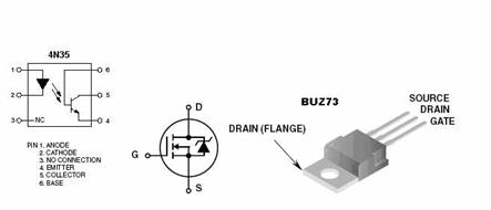
Figure 8: Optoisolator circuit used to drive the motor. A 9V battery
was used on the motor end.
|
Item |
Number Used |
Cost |
|
Mega32
chip |
2 |
$16.00 |
|
Custom
PC board |
2 |
$10.00 |
|
Batteries |
3 |
$6.00 |
|
Small
solder board |
1 |
$1.00 |
|
Freescale solder boards |
7 |
Scavenged |
|
ZHX1810
IR Transceiver |
2 |
$8.10 |
|
MCP2120
IR Endec |
2 |
Sampled |
|
IESP12
Force Sensor |
3 |
Sampled |
|
LCD |
1 |
$8.00 |
|
DC Motor |
1 |
Scavenged |
|
Keypad |
1 |
Scavenged |
|
|
Total |
$49.10 |
|
Task Assigned |
Person |
|
Parts
acquisition |
Both |
|
Soldering |
Both |
|
Hardware
setup |
Both |
|
Software
coding |
Both |
|
Implementation
and testing |
Both |
|
IR
background research |
Both |
|
Keeping
the group focused 24/7 |
Cindy |
|
Ensuring
project members were well fed |
Marvin |
Datasheets
IESP 12 Push Button
Force Sensors
MCP2120
Infrared Encoder/Decoder
Vendor
Sites
Code
and Design References
Background
Reference
A big
thank you to