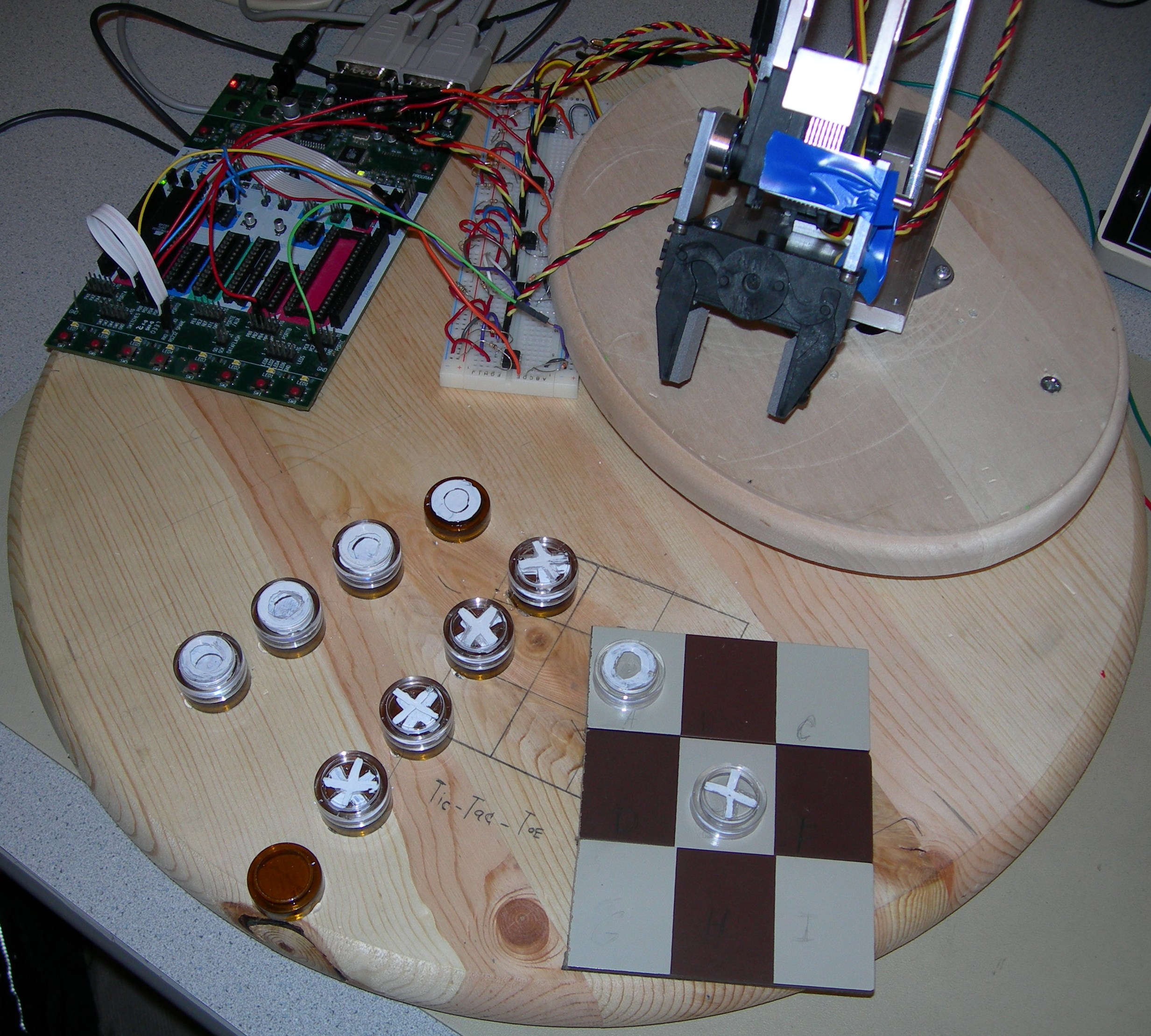
Our project is a twenty four and half inch aluminum frame robotic arm with four degrees of freedom.
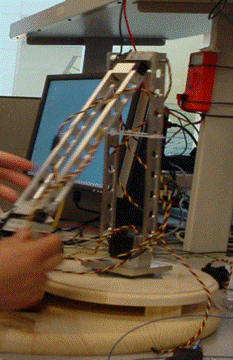
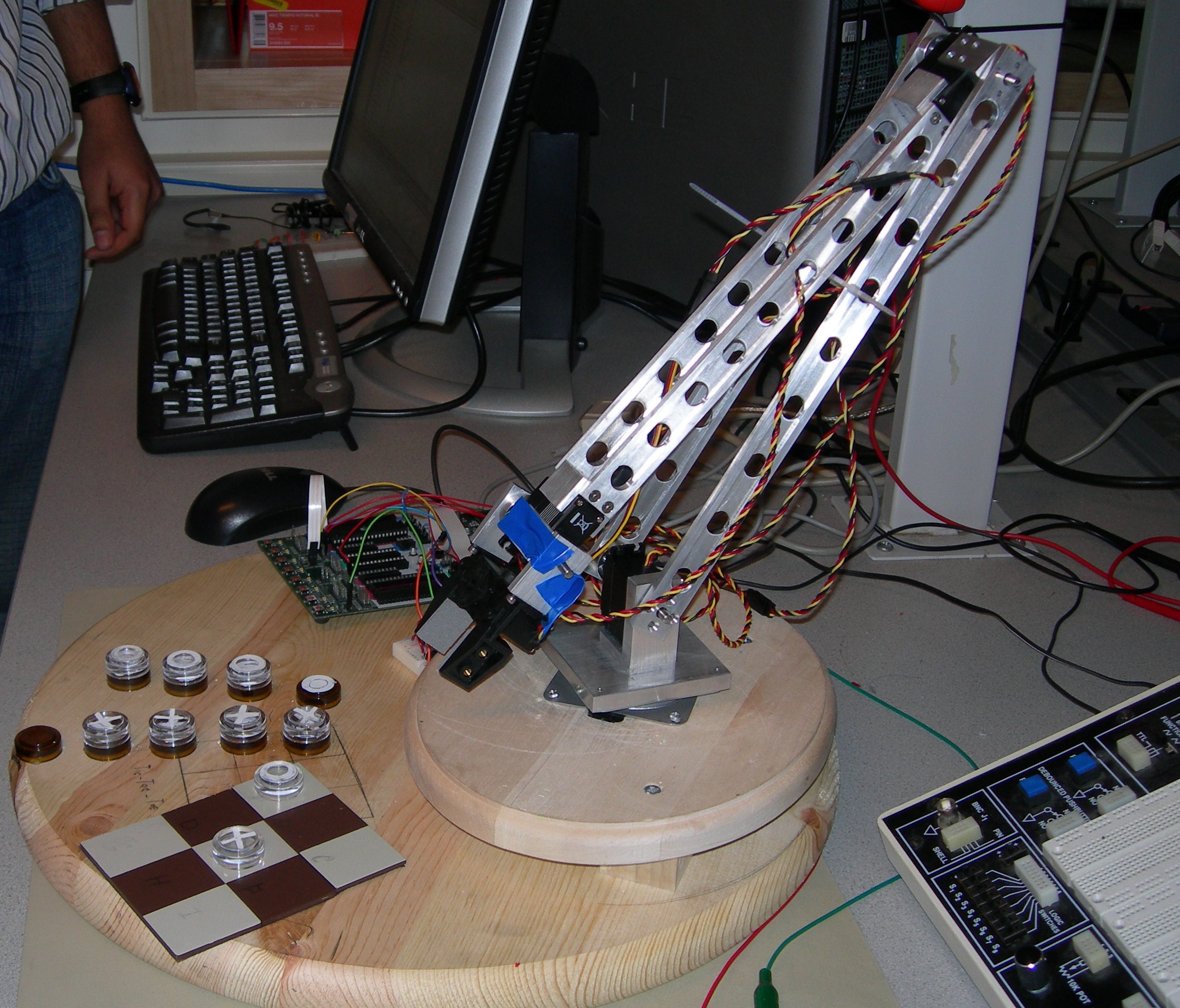
In our project we made the arm the second player in the classic game of Tic-Tac-Toe to demonstrate its programmable repeatable motion. The arm consists of five servo motors, four to control the motion and one to control the end effecter (gripper). The arm moves tic-tac-toe pieces onto a board for its opponent and itself to give the user interactive control over the arm.
This project was a five week design project for ECE 476. Video of the arms ranging from motion, game play, and feats of strength are below in the results section.
High
Level Design
Rationale
We are both members of the CU Snake Arm team so we were aware that the 2008 CU Snake Arm was lacking a delivery vehicle. Typical snake arms are attached to industrial robotic arms. So we both thought that it would be nice to build a scale model for a possible delivery system or a possible end attachment for a future snake arm.
Background Math
This project does not implement inverse kinematics calculation on the mcu but we did make use of forward kinematics to aid in programming position. The forward kinematics determines the location and angle of the end effecter. To begin the calculation find the position of the first joint (x1,y1). Assuming that the turntable is at position (x0,y0) and the length of the segments of the arm are L1 and L2 receptivity the calculations go as follows.
x1= L1cos(theta1) + x0
y1 =L1sin(theta1) + y0
The position of the second joint is given by:
x2 =x1 + L2cos(180-theta1-theta2)
y2= y2 + L2sin(180-theta1- theta2)
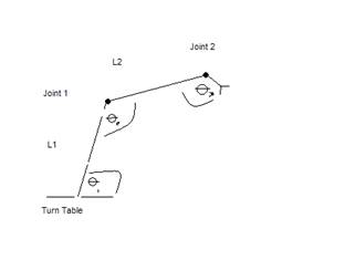
We define the angles to be those formed by two segments next to another, making them more easily observed. Theta3 in our project was desired to be perpendicular to the horizontal axis and was (270 –theta1 –theta2) in the first quadrant.
Patents,
Copyrights and Trademarks
Although a servo
controlled robotic arm and Tic-Tac-Toe are not new ideas, there are no
patent,
copyright, or trademark issues involved with the project. The arm was designed by
the CU Snake Arm Team.
Program/Hardware
Design
Logical Structure
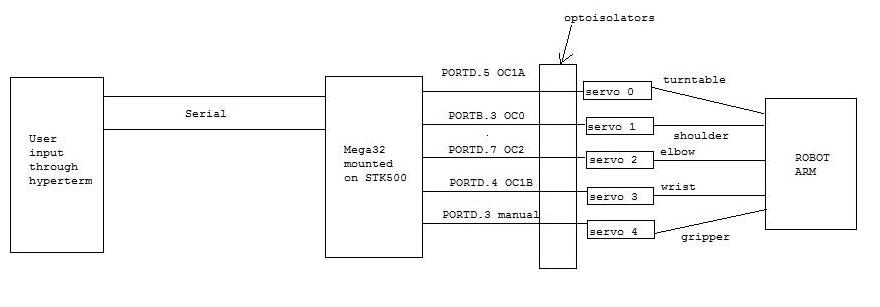
The logical structure of the
design is shown
below:
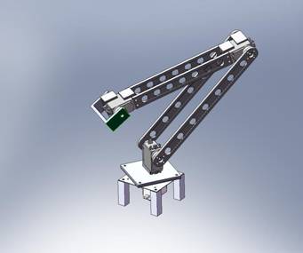
Mechanical Details
Below is a CAD picture of the arm. The complete CAD assembly
and part files are in
appendix B. These
files contain all the
measurement data. The parts for the arm were machined in Emerson Lab at
Hardware/Software Tradeoffs
The hardware tradeoffs we were
considering
involved the use of Hitec-5995TG servo motors with an average holding
torque
limit of approximately 2.2 ft lbs, as opposed to perhaps building a
smaller arm
with less powerful motors which would require less voltage to operate.
We
decided to go with the larger arm which was just within the limit of
the more
powerful servos. To get the power supply voltage at least up to 6 V, we
decided
to use a 6.4 V, 2 A current DC adapter.
The software tradeoff involved
thinking about
whether we needed to create manual PWM waveforms with a delay of at
least 20 ms
between pulses or use the in-built timers in the Mega32. For the most
part we
decided to use the timers because we discovered that it didn’t make any
difference as to what delay we supplied between pulses. However, we ran
out of
timers to use once we got to servo 4, and so we had to generate a
manual PWM
waveform for the gripper servo.
Standards
The applicable standards were set
by our own
snake arm team. Any robotic arm built by us would have to use servo
motors, and
would have to have repeatable control with programmability.
Hardware Design
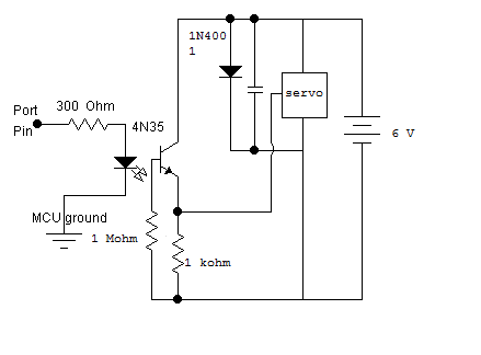
The hardware design involved building the circuitry for controlling the servos on the robot. As stated before, we used Hitec 5995TG servo motors, which operate within a power supply voltage range of 4.8 – 7.4 V. In order to rotate them, they require a PWM signal with a pulse width between 1100 us and 1900 us. The width is proportional to the angle of rotation. We used a 6 V DC adapter for the required power supply. However, if the servo is directly connected to the PWM output from the Mega32, the ground terminal of the power supply needs to be jumped to the ground of the Mega32 board. This not only makes the Mega 32 highly prone to spikes in the power supply, but also leaves the PWM signal noisy and unfiltered. This affects the servos by way of switching them off randomly or making the arm vibrate when it is supposed to remain in position. To solve these issues, we needed to build an optoisolator circuit, similar to that used in Lab 5. The circuit diagram is shown in Appendix B.
The 4N35 optoisolator when used in a circuit such as in the appendix isolates the ground terminals of the power supply and the MCU while still providing the required PWM input to the servo. We built 5 such optoisolator circuits for the 5 servos on the arm, with an effective 0.3 uF capacitance across the power supply in addition to the 4N001 diode.
For the servos controlling the turntable, shoulder, elbow and wrist joints, namely servos 0, 1, 2 and 3 in our program, we used the timers on the Mega32 in fast PWM mode. The PWM output waveform of the timers used appears at Ports D.5, B.3, D.7 and D.4 respectively. Servo 4, the servo controlling the gripper, was fed by a manual PWM waveform generated at Port D.3. Each of these ports was connected to the input pin of the respective optoisolator circuit for that servo.
The
overall hardware design is very
simple and can be easily replicated in the lab.
Software Design
The
program written for this
consisted of two parts: the AI for the tic-tac-toe game played by the
robot,
and the hardcoded functions for moving the servos in order to make the
robot
pick up tic-tac-toe pieces and drop them onto one of the nine squares
on the
board. Please see the attached code in Appendix A for details about the
specific functions.
PWM waveforms
The servos were controlled by sending PWM signals generated either from the system timers on the Mega32 or by manual PWM waveforms in the case of servo 4. For this, ports B and D were set to outputs by making their corresponding data direction registers, DDRB and DDRD equal to 0xff. The timers used were in the following order: timer 1 (1A) for servo 0, timer 0 for servo 1, timer 2 for servo 2, and timer 1 (1B) for servo 3. All timers were set in fast PWM mode with a speed of 4096 us per PWM cycle. The OCR value for each of these timers was initialized in order to set the servos into convenient reset positions. For example, in the case of servo 2, being controlled by timer 2, the angle of rotation would linearly correspond to the pulse width as follows: 0 degrees – 1100 us, and 180 degrees – 1900 us. These times were scaled down to an integer between 0 and 256 by the following equation: integer = (pulse width/4096 us) * 256, thus changing the above relation to 0 degrees – 69, and 180 degrees – 118. The equation thus used for setting OCR2 was OCR2 = ((118-69)/(180-0))(desired angle of rotation) + 69 = 0.27(desired angle of rotation) + 69. In the moveServo(int servo, int angle) function, the OCR value for moving a particular servo from 0-3 was slowly incremented or decremented to the passed value in order to provide a steady, clean motion.
In the case of servo 4, a timer was not used, but a manual waveform was generated for about 1 s in the moveServo() function in the program. The output appeared at Port D.3, which was asserted for a given delay (called ‘servo4’) and then negated for 20 ms. Since the microsecond delay function delay_us obtained from delay.h is unable to accept a variable delay duration, we had to write our own delay function delay_usv(int duration) so that we could delay by the variable duration servo4. However, the way this delay function was written it actually ended up delaying by 1.1*duration instead of duration. We had to account for this unintended scaling factor in the value servo4 supplied to delay_usv() in the moveServo() function. This resulted in the following correlation between angle and delay duration: 0 – 1610 and 180 – 933.
Accepting user input
Since user input for playing the game would be accepted through hyperterm communicating with a serial port, the USART on the Mega32 had to be set up with the UCSRB register equal to 0b10011000, or 0x98, and the baud-rate register UBRRL set to 103. The character-receive ISR was written in the program to implement the corresponding interrupt. The receive buffer (char r_buffer[16]) was built in this ISR, and supplied to the main program to be read.
Hard-coded motion
Sequences
of servo movement were
hardcoded into the program for picking up tic-tac-toe pieces and
placing them
onto given squares on the board. The function pickup(int piece, int
num) was
used for picking up any of the four o’s and five x’s laid out on the
base
surface, and the function drop(int x, int y) was used for placing the
picked up
piece on the square given by the row and column coordinates x and y on
the
board. The function neutral() was used for moving back to a neutral
position
between pickup and drop, and involved pulling back on servo 1 to move
the
shoulder back.
Game play and AI
The game was essentially played in the main loop of the program. The loop ran for five turns of the game. At every turn, the loop would check for user input, which would be essentially be an alphabet from ‘a’ to ‘i’, indicating the square on which the user wished to move an x. The program would then call on the move(int piece, int x, int y) function with piece = 1 to move the next x piece to the given position. The move function would call on the pickup, neutral and drop functions written above to move the piece. It would also set the corresponding value in the 2-D board array to 1, representing an x in that position. The 2-D board array was an integer array representing the current layout of the board. At each location, there was stored either a -1, 1 or 0 depending on whether there was an o, an x or nothing at that square.
After
performing the user’s move,
the program would then move an o to a location on the board based on
the AI
functions programmed into it. The following figure shows the flow and
structure
of the AI used for every turn:
Results
Speed: The speed was controlled by the manual delays written in the OCR updating routine in the moveServo() function. The OCR value would be incremented or decremented by 1 depending on which way the servo had to be moved relative to the current position, with intermediate delays of 60 ms in order to provide a relatively smooth and steady movement in terms of speed. This would avoid sudden jerks in motion which could damage the mechanical parts.
Accuracy: The pickups and drops were surprisingly accurate every time we tested, except for a few occasions. Because the motion was hardcoded in, it was relatively easy to change or recalibrate the pickups in case any of the segments had to be re-tightened.
Safety: The only safety issues arising from the design were the moving parts snapping quickly to injure people. However, we took care of these issues by setting the reset values in the initialize() function to safe positions, and then only moving the arm within the base area for game-play. We did not move it to extreme positions which would pose a danger.
Interference: The only interference issues arising were the shrill noise emanating from the servos which could have bothered other groups, but there were no RF or other EM-radiation interference problems.
Usability: The game was easily playable by us or anyone else because the only user input involved entering a letter from a to i and the arm would do the rest of the work.
Conclusions
The arm did meet our expectations. The arms length at over
two feet did make
certain positions less dependable given that the max torque of the
servo was
around two foot pounds and the fully constructed arm was around one
pound. We also
would have liked to add perhaps a
sensor array to the arm to aid the control algorithm and to verify the
arm’s
position.
The only applicable standards were
standards set
by our own snakearm team, which include the rule that any design
pertaining to
our current snakearm project must involve the use of servo motors or
any other
kind of motors, and not actuators or other motion control mechanisms.
Also we
needed repeatable control and programmable positions, both of which we
were
able to achieve.
Ethics
and Legal Considerations
The
IEEE code of conduct was
followed in the construction of this project. Safety was
always the highest priority in the construction
of the arm and its use. Before the arm was powered up we connected to a
secure base and made sure that the work area was clear. These
ensured that we did not injure lab equipment or our peers in the
process of completing our project. Along with safety we tried to
ensure a fair work environment to everyone around us by leaving our
work area cleaner than we found it. We also tried to maintain a calm
and helpful atmosphere even when pulling an all-nighter and while
debugging. We also maintained a high degree of integrity and answered
any questions in lab with the utmost honestly. We tried to
increase understanding of technology when answering questions.
We also sought
and accepted any improvements to the code and to the arm during our
time in the lab. Although during our time in lab we were
offered
no bribes, if the situation would have arisen, we would have rejected
them in
any form. We do not have any legal considerations since we did not use
code from other sources and did not use parts regulated by agencies
such as the FCC. The arm was built from a CAD design that we created
and the game of Tic-Tac-Toe is not trademarked.
Appendix
A. Program Code
Note: If it doesn't open, right click and choose "Save target as"
B. CAD Pictures and Circuit Schematics
Arm
CAD Pictures
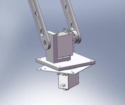
Arm
base/shoulder joint
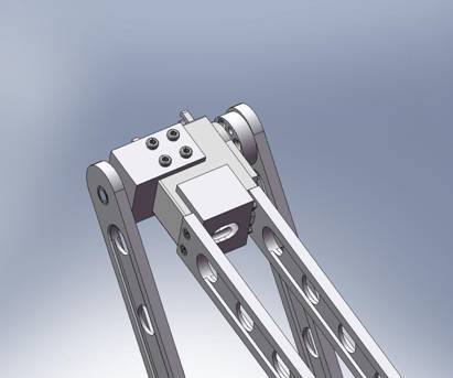
Arm
elbow joint
Optoisolator
circuit schematic
C. Cost Details
Our budget did exceed the $75 dollar limit, but this limit was waived due to our association with the CU Snake Arm team. As seen below several expense servos where borrowed from the team in the construction of this arm.
|
Item |
Part # |
Quantity |
Price |
Total Price |
Location |
|
Aluminum |
8975K22 |
1 |
11.24 |
11.24 |
McMaster |
|
Aluminum |
8975K91 |
1 |
11.59 |
11.59 |
McMaster |
|
Aluminum |
9008K151 |
1 |
16.90 |
16.90 |
McMaster |
|
Turn Table |
6031K16 |
1 |
1.87 |
1.87 |
McMaster |
|
Bearings |
57155K352 |
3 |
7.50 |
22.50 |
McMaster |
|
Dowel Pins (10) |
90145A508 |
1 |
6.37 |
6.37 |
McMaster |
|
Machine Screws (30) |
91771A126 |
1 |
6.18 |
6.18 |
McMaster |
|
Set Screws (25) |
92778A117 |
1 |
6.18 |
6.18 |
McMaster |
|
HS5955-TG Servos |
------------ |
5 |
Borrowed ( $85) |
------------ |
Snake Arm |
|
Gripper |
|
1 |
14.85 |
14.85 |
RobotStore.com |
|
Servo Extenders |
------------ |
4 |
Borrowed |
------------ |
Snake Arm |
|
STK 500 |
------------ |
1 |
Rent |
15 |
476 Lab |
|
Mega 32 |
------------ |
1 |
Rent |
8 |
476 Lab |
|
330 Resistor |
------------ |
5 |
------------ |
------------ |
476 Lab |
|
1K Resistor |
------------ |
5 |
------------ |
------------ |
476 Lab |
|
1 M Resistor |
------------ |
5 |
------------ |
------------ |
476 Lab |
|
Phototransistor |
4n35 |
5 |
------------ |
------------ |
476 Lab |
|
White Board |
------------ |
1 |
------------ |
------------ |
476 Lab |
|
Diodes |
1N4001 |
5 |
----------- |
----------- |
476 Lab |
|
16 MHz Crystal |
------------ |
1 |
------------ |
------------ |
476 Lab |
|
6.4V 2.0 Amps Power Supply |
------------ |
1 |
Borrowed |
------------ |
Snake Arm |
|
Wood Table Top |
------------ |
1 |
10 |
10 |
Lowes |
|
Wood Mount |
------------ |
1 |
7 |
7 |
Walmart |
|
Total |
|
|
|
131.31 |
|
- Joseph Swingle built the base and constructed the arm.
- Aditya Anchuri wrote the code for serial communication and servo control.
- We both wrote the tic-tac-toe algorithm and game play code.
- We both calculated and found servo paths for the game play code.
- We both designed the build the opto-isolators.
- We jointly wrote this lab report.
- The website was formatted to Cornell guidelines by Aditya Anchuri.
E. References
The structural idea of PWM control for the servos was obtained from the following page:
http://www.convergencepromotions.com/atmelonline/v_9/pdf/AtmelJournal_V9_ConstructingA16-Channel.pdf
The servo datasheet is located at: http://www.servocity.com/html/hsr-5995tg_ultra_torque.html
The
following was
the link for the kinematics calculation ideas: http://www.societyofrobots.com/robot_arm_tutorial.shtml#inverse_kinematics
The Atmel Mega32 datasheet was also used.
F. Acknowledgements
We would like to thank Bruce Land
and the TA’s of
this course for their help in the lab, not only for this final project
but
throughout the year. We would also like to thank them for maintaining
the
extended lab hours throughout the year.
We
also
like to thank Brian Johnson for his help in the fabrication of the arm
and for
SoildWorks CAD.