Introduction
One Sentence Sound Bite
Air Drums is an electronic drum kit played in the air that eliminates the need for tactile drum pads.
Summary
We created an electronic percussion set with three upright percussion sounds and a floor bass drum sound. The upright instruments require one/two modified drumsticks to play, while the floor drum requires an electronic bass pedal. The important difference between our drum kit and store bought drum kits is the lack of drum pads. Instead, our drum kit can be played entirely in the air, eliminating the distracting tapping noise that comes from the drum pads. This means you can play the Air Drums in your room with a set of headphones without annoying your next-door neighbor!
High Level Design
Rationale
The inspiration for our project came from multiple occasions of being scolded by our roommates for playing the Rock Band drums too loudly (all while wearing headphones). The rationale behind our project was to create a drum kit that would not make any noise when played. While ordinary electronic drum kits claim to be silent since the noise they produce can simply be filtered through headphones, this is not the whole truth. The loud rap of the drum sticks hitting the drum pads carries a great distance. The loud beat has been known to be just as annoying to roommates and apartment mates as the sound of actual drums. For this reason we wanted to eliminate the drum pads and therefore the loud rapping noise. The idea was wireless drum sticks with a speaker component that can be plugged into headphones. This will eliminate all ambient noise as there is no actual contact with a surface of any kind. In addition, Air Jam, the air guitar project from the 476 project page, inspired the idea to create an entire air band.
Background Math
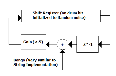
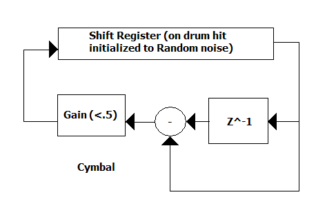
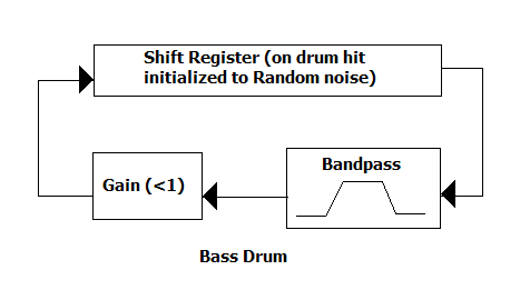
The background math for this project was required for the drum sound synthesis. Instead of using direct digital synthesis recorded sound playback, as we did in previous labs, we chose to use the Karplus-Strong digital signal processing algorithm to create accurate drum sounds. The Karplus-Strong algorithm is a digital approximation of the way a wave decays in a string or on a drum. Using a shift register, when the instrument is struck the register is filled with random noise which is the same as the fourier transform of an impulse of energy to the instrument. For drums this shift register is band passed using a butterworth band pass filter, for cymbals we use a low pass filter after subtracting the delayed version of the signal from itself. The frequency of the sound is given by the sampling frequency over the length of the shift register.
Logical Structure
The structure of this project is broken down into three separate tasks: Bluetooth communication, drum sound synthesis, and IR position parsing. The first step, Bluetooth communication, consists of a Wiimote, and a Bluetooth dongle connected to a laptop with Blue Soleil Bluetooth software installed. The Wiimote is used for its CMOS camera technology which can determine the positions of multiple IR LEDs. We have two such IR LEDs which are connected to the tips of drumsticks so we can determine drum tip position. The Bluetooth dongle and Blue Soleil connect to the Wiimote through a Bluetooth connection. From this connection we use the open source Wiimote Lib, written in C#, to query the Wiimote for the position values of up to four IR LEDs in the reference frame of the Wiimotes CMOS camera. After receiving this data we open a serial port and transmit this data to the Atmega32 on the STK500 board through the serial connection.
This leads us to the next step, IR position parsing. In this portion of the code, written on the Atmega32, we receive the serial data transmitted from the laptop software. This information is sent out in packets of information that include the number of the LED whose data is being transmitted, and whether it is the x or y position of the IR LED. This is followed by the actual data. Knowing the format of these packets, we parse these packets in a large switch statement, update the x or y position variable for one of the IR LEDs, and request another packet. From this data we determine which drum is being hit depending on its relative location on the CMOS sensors scope. The scope is simply divided into three equal widths on the x axis. When the y position in each of these scopes is lower than the half way mark and changes from down to up, we play the corresponding drum sound. In addition we play the bass drum noise everytime the bass pedal is hit. This requires no serial communication however since it is connected directly to an input on the Atmega32.
The final task we accomplished in this project was drum sound synthesis. We created four separate drum sounds, a bongo, a mid Tom, a crash cymbal and a bass drum. Each sound we generated using some variation of the Karplus-Strong algorithm which uses different filters on random noise to create sounds. This essentially simulates different instruments and produces a fairly accurate synthesized tone. The algorithm uses different shift registers initialized to hold random noise. When our drum is hit we perform some type of filter on the random noise in the shift register a number of times until the sound decays, based on a decay factor that we introduce. The length of the registers determines the frequency of the sound which is actually produced using a PWM signal from the microcontroller. The calculations for the sound are actually performed in an interrupt that runs at an eighth of the clock frequency. This is necessary since we have a limited amount of space to store variables and the larger the initial interrupt frequency, a longer shift register is required to produce different frequency tones. Finally, as the drum sound is created it is sent from the microcontroller to a set of speakers via the PWM signal.
Hardware/Software Tradeoffs
Our initial plan was to use two Nintendo Wiimotes as the drum sticks in our project. When we realized the amount of added C# code this would have required (plus our very limited experience with C#) this seemed less possible. Furthermore when we began testing by holding a single Wiimote and using multiple IR LEDs for position detection, we noticed that the range of the Wiimotes position was very limited. Because of the very directional IR LEDs, when we changed the yaw of the Wiimote, the camera was facing the IR emission from a different angle and this decreased the position range even further. Instead, we decided to use the Wiimote for its CMOS camera and detect the LEDs as drumsticks. This dramatically increased the position range that we could measure, since we could rotate the LEDs from side to side and the Wiimote could still detect the IR dot in the same x,y position.
Another design tradeoff in our project was the limited amount of memory space on the Atmega32. This space issue significantly limited the size of our shift register arrays, and required us to decrease the frequency of our output sound interrupt by one eighth. This allowed us to reduce the size of the shift registers and produce accurate frequencies despite the size limitations.
Relationship of Design to Standards
The standards relevant to this project include both IEEE standards for Bluetooth as well as ANSI standards pertaining to safety with radio frequencies in hand held wireless communication devices.
IEEE Standard 802.15.1-2005: Bluetooth 1.2 became an IEEE standard in 2005 and defines specifications for wireless connectivity in the Personal Operating Space. We operate the Bluetooth connection within the 10 meter space and used a store bought Bluetooth dongle to interface the Wiimote to the PC. We followed this standard by leaving the Bluetooth connection unmodified by us, and instead we simply received the data.
62209-1 Ed. 1.0 b:2005: This standard assures safety in hand held wireless devices that utilize radio frequencies. We comply with this standard since our projects radiation falls well below the maximum absorption rate limit required for safe human use of handheld wireless devices.
ISO/IEEE 11073-30300:2004: This standard provides a structure for using Infrared communication in hand held devices. The most important part of this standard is adherence to the eye safety clause. We do not exceed the power limit for hazardous operating ranges and therefore meet the Class 1 AEL limit. This means we do not require a warning label on our device.
Patent Discussion
US Pat. 4753146 - Portable Electronic Drum Set
Though this patent certainly relates to our project there are several important differences. First off, we make no claim that our drum set be portable. Secondly, the means for creating drum sticks are completely different than those alluded to in this patent. There would be no way to use IR communication in the schema they devised.
There are other patents pertaining to electronic drums, but other than the above, drumless drums seem to be relatively unique.
Program/Hardware Design
Hardware
There are numerous aspects to the hardware design including the sound output, the Wiimote interface, the drumstick assembly, and the bass pedal interface.
Sound Output
Sound output was handled by PWM outputting through pin B.3. Using a 10-pin header we connected port B to the white board, and filtered the signal using low pass RC circuit. We then connected the filtered sound to the TRS adapter to send to our speakers.
Wiimote Interface
The Wiimote operates wirelessly via the 2.4 GHz Bluetooth communications protocol. Using a Bluetooth adapter on a laptop and the WiimoteLib library provided by Brian Peek we can interface with the Wiimote through the computer. Using serial communication over UART we send the raw data from the Wiimote, specifically the IR LED coordinates to the Mega32. The Mega32 can then analyze the position of the IR LED tipped drum sticks and determine whether an instrument has been struck or not.
Drumsticks
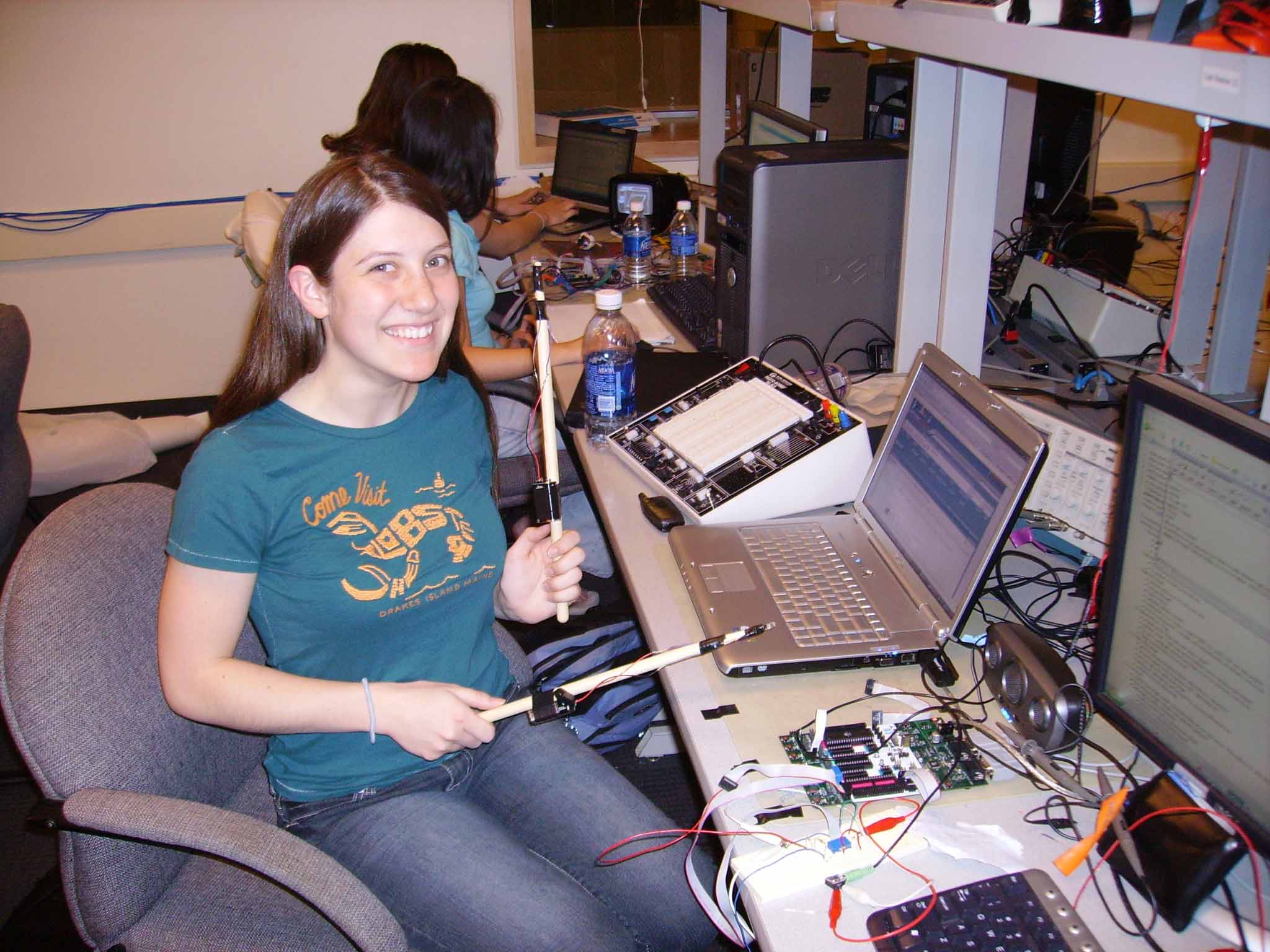
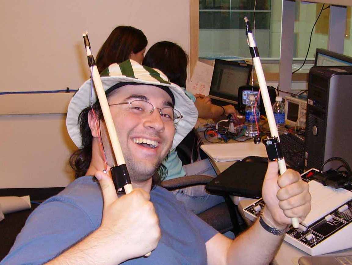
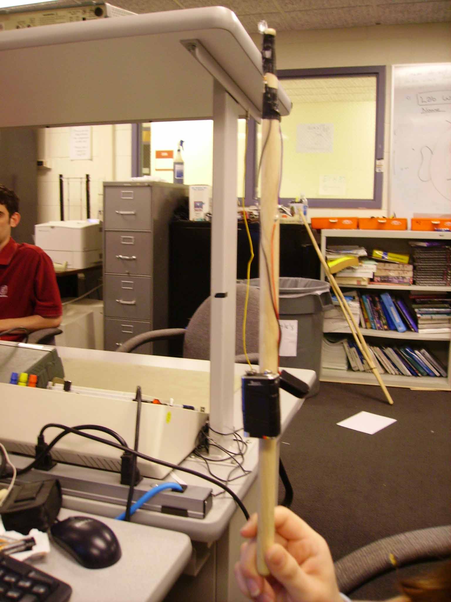
To simulate playing a real drum kit we decided to mount our IR LEDs on the tips of real drum sticks. The assemble was simple: the IR LED was soldered to a 330 ohm resistor and then soldered to a battery clip attached to a standard 9V battery. The whole assembly was then tapped to the drumstick as can be seen in the picture above. The battery clip allowed us to disconnect the LED when not in use to prevent draining the battery power. Finally the addition of the electronics did not change the feel of the sticks much and so the system provides for a relatively natural playing feel.
Bass Pedal
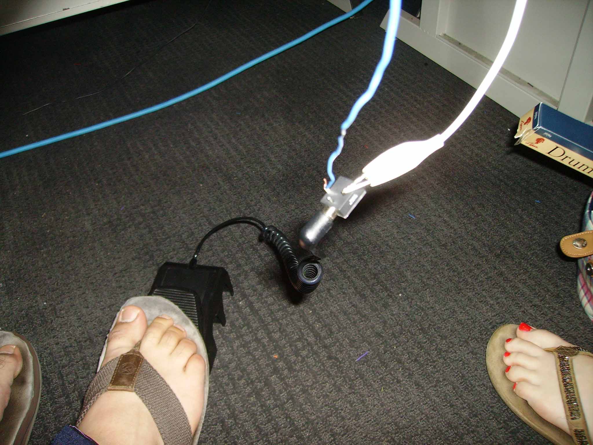
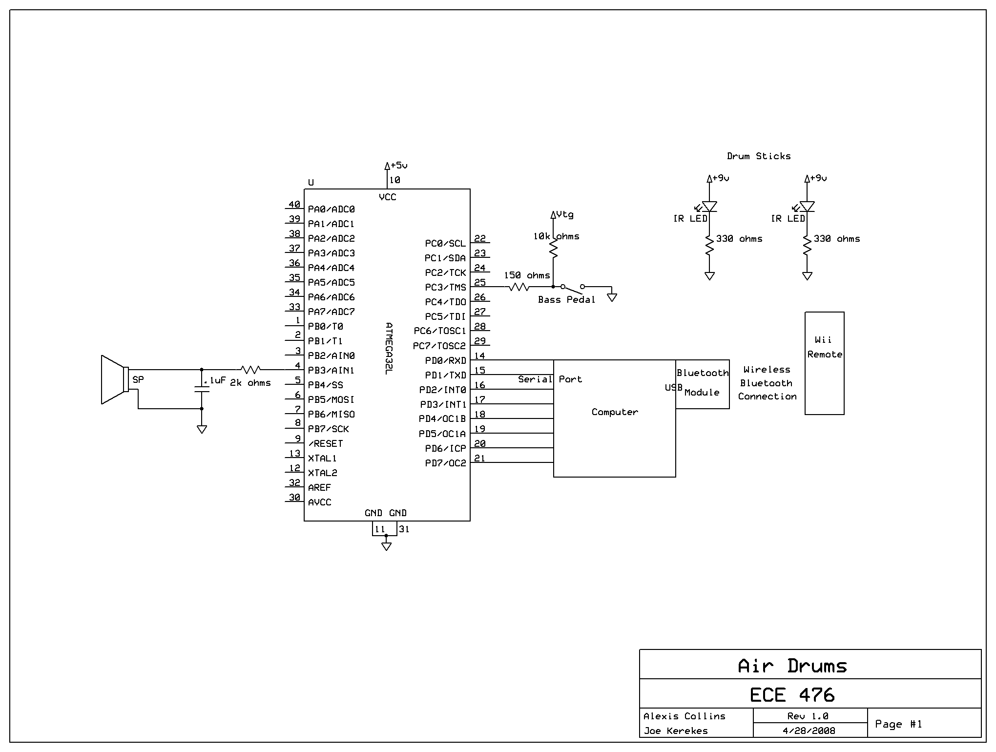
The bass pedal was taken from a Rock Band drum kit. It is essentially a push button operating using a reed switch and a strong magnet. A reed switch is a switch that is operated by magnetic fields. Inside the reed switch are two magnetic and conducting reeds which are separated. When a magnetic field is applied by pressing down on the pedal, the reeds are pulled together and complete the circuit. When the magnetic field is removed, the reeds pull apart. The bass pedal was used to emulate a push button on the STK500 board since it provides a much more authentic feel. It is connected via a mono 1/8" TRS audio cable to a ciruit that active low as seen in the schematic in appendix B.
Software
There are two aspects to the software design of the program. The main component is the embedded C code used to generate our Karplus-Strong based sounds and to interpret IR LED positioning and resulting played instruments. The supplementary part is the C# WiimoteLib test program provided with the library that we modified to include UART communication over serial so that we could send the raw data to Mega32.
Embedded C Mega32 Code
Our system was designed using interrupt driven timing, PWM sound generation, and fixed point 8:8 arithmetic. PWM was run by timer0 set to run at full speed, fast PWM mode, toggling oc0 (pin B3). Timer2 was set to run at 1/8th speed and to trigger an ISR on overflow. The timer2 ISR runs (16Mhz/8)/2^256 = 7812 times a second and calculates the Karplus-Strong algorithm for all our instruments based on flags of which instruments were struck. The ISR running a 7812 times a second allows us to reproduce in PWM a signal of up to 7812/2 = 3906 Hz, which is more than enough for our drums and cymbals.
In timer2 we calculate the result of the Karplus-Strong algorithm based on our inputs. Using message passing between main and the interrupt we can know whether an instrument is played. If an instrument is played, we replace the information in that instrument's shift register with pre filtered (to soften the sound) random values to represent a burst of energy provided to the instrument as explained above. We then update our 'out' variable which represents the sum of each instrument and the total sound of our drum kit. The shift register value is then updated according to the instrument specific Karplus-Strong algorithm. Finally we update our shift register indexes, which are used to avoid actually shifting our registers as this would be too slow. Once all the instrument registers have been updated and the current sound 'out' calculated, it is then written to OCR0 for PWM output, which is constantly running in the background.
Mult_opt was provided by Professor Land and is an optimized 8:8 fixed point multiplication function written in assembly. It was used because of its speed increase over the provided Mega32 functions; x3 over the normal mult and x6 over floating point mult.
Uart_rec and uart_send, provided by Professor Land, are functions for asynchronous serial communication. For receiving, the interrupt triggers when data is sent over the serial while UCSRB.7=1 (receive ISR enable). We continue to receive individual characters until a return character is sent representing the end of transmission. A flag is set to indicate complete reception and the receive ISR enable is turned off. Sending was not needed for our project. Gets_int and puts_int are also used for serial communication. Gets_int resets the receive buffer indices and turns on the receive ISR enable. Again puts_int was not necessary as we don't communicate from the Mega32 to the laptop.
Our main function, after calling initialize(), enters an infinite while(1) loop and controls the data receive, parsing, and hit determination. After receiving data from the C# program over serial UART, it was parsed according to our data packet setup as explained below.
Data received from the Wiimote are four sets of coordinates representing separate IR LED coordinates. X, horizontal coordinates range from 0-1000, while y, vertical coordinates range from 0-760. We split the space horizontally into three separate areas to represent locations for our instruments. 0-333 (space to the user's right) represents our crash cymbal, 334-667 represents our snare/hi tom sounding drum, and 668-1000 represents our bongo. The screen is then split vertically at the halfway point y=380. When an LED crosses over the y threshold, a flag is set and when the drum stick is raised (changes direction), as determined by a simple delta function (old-current) the instrument based on the LED's x location is considered struck. The bass on the floor is a simple switch and so is played when the pedal is released after closing it.
Initialize sets our timers, initializes the UART communication, our indices. Additionally it sets pre calculated butterworth bandpass filter coefficients. These were calculated in matlab using the butter function and based on our drum frequency.
C# WiimoteLib and Serial Code
Using a publically available Wiimote library we modified the provided test code, which continuously monitors the wiimote's state, to open a serial port and to send IR LED coordinate data to the Mega32. We formatted our data packets as four number characters followed by a single letter character. The numbers represent the coordinate, while the letter represents which coordinate and LED the number corresponds to.
Code |
Meaning |
####x |
LED1 XCoord: #### |
####y |
LED1 YCoord: #### |
####a |
LED2 XCoord: #### |
####b |
LED2 YCoord: #### |
####c |
LED3 XCoord: #### |
####d |
LED3 YCoord: #### |
####e |
LED4 XCoord: #### |
####f |
LED4 YCoord: #### |
Despite only using two LEDs in our project, the wiimote has the ability to follow four separate LEDs and occasionally it loses track of which is which and randomly changes what the LED is labelled as. For example, while tracking LED2, the wiimote has sometimes switched it to LED4 and thus if we didn't send that data to the Mega32, no sound would be played.
Problems Encountered
We encountered numerous problems as we developed Air Drums over the course of the month. These issues included, serial communication problems, variable mapping issues, calculating Karplus-Strong algorithms in the actual PWM interrupt and not a separate one, overflowing indices resulting in better sounding drums, and finally random noise in the bass drum producing high pitched wailing sounds.
When we initially implemented serial communication in the C# program in order to send the raw wiimote data, we had already tested the link by using hypertrm to verify proper communication. However, in the C# program, after a few seconds of communication, the C# program would crash. It was finally determined that the C# program was attempting to write too often to the serial port and thus started storing data into a buffer, which would then overflow. With the help of CS friend we resolved this by discarding the buffer after one pass of the data. This prevents a buffer overflow and insures the most recent data.
Originally we had calculated Karplus-Strong algorithms in the actual PWM interrupt every eigth time in the interrupt. This proved disastrous, prompting several other errors, namely the mapping issues and overflowing indices sounding better. When we had two instruments and tried adding a third, simply declaring another shift register broke the sounds, as variables were mapped over one another for some reason. The bad indices were the result of sheer chance. We had accidentally started indexing arrays from one, instead of zero. Surprisingly the sound was still nice (for our two instruments). However when we noticed and changed the indices to the correct values so there were no overflows, the sound became incomprehensible. On the advice of Professor Land we used another interrupt to calculate Karplus-Strong algorithms for instruments and thankfully the above mentioned problems went away.
The last issue was that ocassionally our bass drum would become a high pitched wail sound. On the advice of our TA Rob Zimmerman, we figured out that the random number generator was perhaps generating amplitudes that resulted in sound overflows of some type. After some testing we determined that numbers above 17500 would result in the loud squeeking and so we modded the rand() function with 17500 to ensure that we never go above. After this fix, the bass drum never squeeked again.
Results of the Design
Accuracy and Speed Testing
The final code produced a usable drum kit with three upright percussion sounds and one bass drum. All sounds were clear, able to be played concurrently with little lag. However, we decided to quantitatively test our design. We conducted three tests of our design, reaction time of the system from physical striking to hearing the sound, accuracy of playing individual instruments, and how fast we can play successive notes.
First Test
During intermediate testing of our system there was significant lag in playback so we felt we could measure the difference from striking an air drum physically and then hearing the sound. However, with final code, the delay is virtually non existent if the system detects the hit, and any attempt to measure it was based solely on human reaction time.
Second Test
The second test was an accuracy test to see whether the system failed to detect what a user would reasonably expect to be a hit. We played a set of ten strikes per instrument. The results are as follows:
Instrument |
Number Hit out of 10 |
Accuracy |
Notes |
Bongo |
10 |
100% |
Played the crash sound at 3 |
Hi Tom |
9 |
90% |
Missed 6th |
Crash |
8 |
80% |
Missed 3rd and 7th |
Bass |
10 |
100% |
~ |
Third Test
The third and final test was a speed test to measure how fast our system can detect and play continuous strikes. This was measured by quickly 'hiting' the bongo air drum and measuring how long it takes to reach 40 played strikes. We repeated this test four times and the results were averaged as follows:
Test Set |
Time to play 40 / s |
Played per second |
1 |
9.02 |
4.43 |
2 |
7.46 |
5.36 |
3 |
9.30 |
4.30 |
4 |
11.25 |
3.56 |
Avg: |
4.41 |
Safety Considerations
For safety, the user handles the drum sticks and so we used a basic standard 9V DC battery to power the LEDs attached to the sticks. The wires are covered in electrical tape and a resistor is used to protect the LED. Other safety considerations are that small DC voltages only are required for correct operation aside from the power supply to the STK500.
Interference
We did not experience any interference as no one to our knowledge was working in the same high freq wireless band other than one other group that used Wiimotes. Since bluetooth requires handshaking we were not interefering with each other during development.
Usability
When we completed our system we invited other people to play our system. People found it enjoyable, although it took a few moments to become accustomed to the placement of the drums in the air. We placed stripes of tape to indicate general locations to help people visualize the drum locations.
Conclusions
Our Expectations
From our original proposal our project evolved quite a bit. We expected to use the Wiimotes as the physical drumsticks and rely on three dimensional positioning to account for our interpretation of the drum heads. We quickly changed from using two Wiimotes to using a single Wiimote and two drumsticks with attached IR LEDs. We also eliminated three dimensional positioning as we decided this was unnecessary and needlessly complicated. Instead we focused more on the Karplus-Strong algorithm and the synthesized drum sounds. Obtaining accurate sounding drum sounds seemed to be harder than anticipated. It was partially the use of the algorithm and then a bit of tweaking by ear. For this reason our drum sounds are not entirely perfect. If we were to do this project again we would certainly budget more time to improving our synthesized drum sounds. In addition, there was a bit of lag between drum hits and the actual noise sounding. This lag and the occasional glitches seemed to be caused by a loss of data from serial communication. If we were to improve this project in the future we would consider using a different method of Bluetooth to serial conversion for the Wiimote. A dedicated Bluetooth module would most likely have eliminated the lag from our multitasking PC and since we were not writing the serial code ourselves it probably would have eliminated the loss of data.
IP Considerations
When we were creating the synthesized drum noises we looked at both Bruce Lands matlab code on the Karplus-Strong algorithm for drums, as well as Yuan Ning and Adam Beeces code from last years Karplus-Strong implementation of guitar synthesis on the Atmega32. We adapted Bruces drum code to code from the microcontroller for part of the bass drum sound. We had a very similar implementation to Yuan and Adams Air Jam code for synthesis since we used both PWM and an interrupt driven timer to create musical sounds.
In addition we used code from the public domain. The Wiimote Lib was an open source library written in C# designed for the wiimote. To obtain the IR data from the Wiimote and send it out over the serial port, we adapted this code to fit our needs. They do not require any type of compensation or royalty for use of the code, but it is suggested that we can contact the creators at CodePlex to show them our design.
The similarity to the above patent makes patent opportunities questionable. Though we could not find a project that particularly used a Wiimote and IR LED drum sticks, it is entirely plausible that a patent is already being created, or has been created.
Ethical Considerations
In the lab, there was one other group using Bluetooth communication, in addition to many Bluetooth devices in the lab. To minimize any possible interference with the other Bluetooth group, we sat as far away from them as possible and from any Bluetooth enabled laptops. In addition, the two Bluetooth groups assisted each other with any information we had relating to the two projects. We constantly stayed in contact and if we made any interesting advancements, we were sure to communicate them to the other group. Unfortunately, while we had similar problems, they were usually solved in completely different ways since we were using two entirely different operating systems to run our Bluetooth to serial programs. But nonetheless group communication provided both groups with different perspectives on different implementations of similar code. Aside from Bluetooth communication, when playing our synthesized drum noises in the lab we kept our speaker volume as low as possible to minimize distractions to other groups. We also warned people when we were worried that an annoying noise would be produced. In one particular case, we had to test when said annoying noise would occur and we kept the volume very low and shut off the system immediately after the noise was produced. We tried to be very mindful of the close space in the lab and respect the space of others around us.
Appendix A: Code
#include <Mega32.h>
// define a new I/O register for easier programming
sfrw ICR1=0x26;
#include <delay.h>
#include <stdio.h>
#include <math.h>
#include <stdlib.h>

#define begin {
#define end }
#define big 130    //Noise register size
#define p 100    //Crash register size
#define p0 130     //Bass register size
#define p1 50    //Hi Tom register size
#define p2 20    //Bongo register size

#define fix2int(a) ((signed char)((a)>>8))
#define float2fix(a) ((int)((a)*256.0))

void initialize(void);

unsigned int j;
unsigned char iHH, iSR, iHiTom;
//the  subroutines

void gets_int(void);    //starts getting a string from serial line
void puts_int(void);    //starts a send to serial line
void initialize(void);     //all the usual mcu stuff
int mult_opt(int a, int b);

unsigned char v[16];

int x1, x2, x3, x4, y1, y2, y3, y4, oldy1, oldy2, oldy3, oldy4; //IR LED coordinates

int Sound[p2];      //Bongo register
int HiTom[p1];     //HiTom register
int HH[p];        //Crash register
int SR[p0];        //Bass register
int out;         //Final sound output for PWM

//indices
int oldptrout, oldptrout1, oldptrout2;
int oldptrin, oldptrin1, oldptrin2;
int ptrout[3];
int ptrout1[3];
int ptrout2[3];
int ptrin[3];
int ptrin1[3];
int ptrin2[3];
int factor[3];
int incr;

//Butterworth filter coefficients
int a[3];
int a1[3];
int a2[3];
int b[3];
int b1[3];
int b2[3];

//RXC ISR variables
unsigned char r_index;              //current string index
unsigned char r_buffer[16], inputCode;    //input string
unsigned char r_ready;              //flag for receive done
unsigned char r_char, itsThere;          //current character

//TX empth ISR variables
unsigned char t_index;      //current string index
unsigned char t_buffer[16];    //output string
unsigned char t_ready;      //flag for transmit done
unsigned char t_char, i;      //current character

//Flags for communication
unsigned char count8, weHit, weHit1, weHit2, weHit3, ready, ready1, ready2, readyb,
                      ready1b, ready2b, readyc, ready1c, ready2c,
                      readyd, ready1d, ready2d, ready3;


//**********************************************************
//timer 0 overflow ISR
interrupt [TIM2_OVF] void genSound(void){

    ////////////////////////////////////////
    //                     Crash C.                      //
    ////////////////////////////////////////

    //If we strike, input somewhat filtered noise. Filtering to soften 'impact'
    if (weHit1 == 1){
        for (i = 0; i < p; i++){
            if (i==0){
                HH[i] = rand();    //'noise' is just random values
            }
            if (i==1){
                HH[i] = mult_opt((rand() + HH[i-1]),float2fix(.49));
            }
            else{
                HH[i] = mult_opt((mult_opt((rand() + HH[i-1]),float2fix(.49)) + HH[i-2]),float2fix(.49));
            }
        }
        weHit1 = 0; //Turn hit flag off
    }
    out = HH[oldptrin];    //get sound
    //Calculate Karplus-Strong for Crash. Subtracts time delayed signal from current
    HH[oldptrin] = mult_opt(((HH[oldptrin])-(HH[oldptrout])), float2fix(.49));

    //Update Indices
    if (oldptrin == p-1) oldptrin = 0;
    else oldptrin = oldptrin + 1;
    if (oldptrout == p-1) oldptrout = 0;
    else oldptrout = oldptrout + 1;

    ////////////////////////////////////////
    //                      Hi Tom                      //
    ////////////////////////////////////////

    //If we strike, input somewhat filtered noise. Filtering to soften 'impact'
    if (weHit2 == 1){
        for (i = 0; i < p1; i++){
            if (i==0){
                HiTom[i] = rand();
            }
            if(i==1){
                HiTom[i] = mult_opt((rand() + HiTom[i-1]),float2fix(.49)) ;
            }
            else{
                HiTom[i] = mult_opt(
                (mult_opt((rand() + HiTom[i-1]),float2fix(.49)) + HiTom[i-2]),float2fix(.49));
            }
        }
        weHit2 = 0; //Turn hit flag off
    }

    out = out + HiTom[ptrin[1]];     //Add sound to total
    //Calculate Karplus-Strong for hi-tom. While a drum, a fast decay
    //high pitch cymbal algorithm sounded nice.
    HiTom[ptrin[1]] = mult_opt(((HiTom[ptrin[1]])-(HiTom[ptrout[1]])), float2fix(.4));


    //Update Indices
    if (ptrin[1] == p1-1) ptrin[1] = 0;
    else ptrin[1] = ptrin[1] + 1;
    if (ptrout[1] == p1-1) ptrout[1] = 0;
    else ptrout[1] = ptrout[1] + 1;

    ////////////////////////////////////////
    //                     Bongo                         //
    ////////////////////////////////////////

    //If we strike, input somewhat filtered noise. Filtering to soften 'impact'
    if (weHit3 == 1){
        for (i = 0; i < p2; i++){
            if (i==0){
                Sound[i] = rand();
            }
            if(i==1){
                Sound[i] = mult_opt((rand() + Sound[i-1]),float2fix(.49)) ;
            }
            else{
                Sound[i] = mult_opt(
                (mult_opt((rand() + Sound[i-1]),float2fix(.49)) + Sound[i-2]),float2fix(.49));
            }
        }
        weHit3 = 0; //Turn hit flag off
    }

    out = out + Sound[ptrin[2]];     //Add sound to total

    //Calculate K-S for bongo. Sounded good as a fast decay
    //high pitch guitar string algorithm.
    Sound[ptrin[2]] = mult_opt(((Sound[ptrin[2]])+(Sound[ptrout[2]])), float2fix(.49));


    //Update Indices
    if (ptrin[2] == p2-1) ptrin[2] = 0;
    else ptrin[2] = ptrin[2] + 1;
    if (ptrout[2] == p2-1) ptrout[2] = 0;
    else ptrout[2] = ptrout[2] + 1;

    ////////////////////////////////////////
    //                 BASS DRUM                   //
    ////////////////////////////////////////

    //If we strike, input somewhat filtered noise. Filtering to soften 'impact'
    if (weHit == 1){
        for (i = 0; i < p0; i++){
            if (i==0){
                SR[i] = rand()%17500;       //Used to go crazy with full rand. If values exceed 17500,
                                    //the speaker starts squeeking loudly
            }
            if(i==1){
                SR[i] = mult_opt((rand()%17500 + SR[i-1]),float2fix(.49));
            }
            else{
                SR[i] = mult_opt(
                (mult_opt((rand()%17500 + SR[i-1]),float2fix(.49)) + SR[i-2]),float2fix(.49));
            }
        }
        weHit = 0; //turn hit flag off
    }

    out = out + SR[ptrout[0]];     //Add sound to total

    //For K-S drum algorithm we need to band pass filter. We used a butterworth bandpass
    //Based on Prof Land's matlab code
    SR[ptrout[0]] = mult_opt(factor[0], (mult_opt(SR[ptrin[0]],b[0]) +
                mult_opt(SR[ptrin1[0]],b[1]) -
                mult_opt(SR[ptrin2[0]],b[2]) +
                mult_opt(SR[ptrout1[0]],a[1]) -
                mult_opt(SR[ptrout2[0]],a[2])));

    //Update indices
    if (ptrin[0] == (p0-1)) {ptrin[0]=0;}
    else ptrin[0] = ptrin[0]+1;

    if (ptrin1[0] == (p0-1)){ ptrin1[0]=0;}
    else ptrin1[0] = ptrin1[0]+1;

    if (ptrin2[0] == (p0-1)) {ptrin2[0]=0;}
    else ptrin2[0] = ptrin2[0]+1;

    if (ptrout[0] == (p0-1)) {ptrout[0]=0;}
    else ptrout[0] = ptrout[0]+1;

    if (ptrout1[0] == (p0-1)){ ptrout1[0]=0;}
    else ptrout1[0] = ptrout1[0]+1;

    if (ptrout2[0] == (p0-1)) {ptrout2[0]=0;}
    else ptrout2[0] = ptrout2[0]+1;

    ////////////////////////////////////////
    //                 Output Sound                  //
    ////////////////////////////////////////

    OCR0 = fix2int(out)+128; //Play the sound! Woo!
}

//Prof. Land's optimized fixed point 8:8 multiplier
int mult_opt(int a, int b)
begin

    #asm
    ;push r20
    ;push r21
    mov  r24,r20
    mov  r25,r21

    ldd  R22,Y+2  ;load a
    ldd  R23,Y+3

    ld  r20,Y   ;load b
    ldd r21,Y+1

    muls    r23, r21    ; (signed)ah * (signed)bh
    mov        r31, r0        ;
    mul        r22, r20    ; al * bl
    mov     r30, r1        ;
    ;mov    r16, r0
    mulsu    r23, r20    ; (signed)ah * bl
    add        r30, r0     ;
    adc        r31, r1     ;
    mulsu    r21, r22    ; (signed)bh * al
    add        r30, r0     ;
    adc        r31, r1     ;

    mov r20,r24
    mov r21,r25
    ;pop r21
    ;pop r20
    #endasm
end

//**********************************************************
//UART character-ready ISR
interrupt [USART_RXC] void uart_rec(void)
begin
    r_char=UDR;    //get a char
    UDR=r_char;    //then print it

    //build the input string
    if (r_char != '\r') r_buffer[r_index++]=r_char;
    else
    begin
        putchar('\n');              //use putchar to avoid overwrite
        r_buffer[r_index]=0x00;        //zero terminate
        r_ready=1;                //signal cmd processor
        UCSRB.7=0;               //stop rec ISR
    end
end

/**********************************************************/
//UART xmit-empty ISR
interrupt [USART_DRE] void uart_send(void)
begin
    t_char = t_buffer[++t_index];
    if (t_char == 0)
    begin
        UCSRB.5=0;     //kill isr
        t_ready=1;     //transmit done
    end
    else    UDR = t_char ;    //send the char
end
/**********************************************************/

//**********************************************************
//  -- non-blocking keyboard check initializes ISR-driven
// receive. This routine merely sets up the ISR, which then
//does all the work of getting a command.
void gets_int(void)
begin
  r_ready=0;
  r_index=0;
  UCSRB.7=1;
end

//**********************************************************
//  -- nonblocking print: initializes ISR-driven
// transmit. This routine merely sets up the ISR, then
//send one character, The ISR does all the work.
void puts_int(void)
begin
  t_ready=0;
  t_index=0;
  if (t_buffer[0]>0)
  begin
      putchar(t_buffer[0]);
      UCSRB.5=1;
 end
end

void main(void){
    initialize();

    //endless loop
    while(1){
        //x is from 0 to 1000
        //y is from 0 to 760
        //format ####x
        //reading and parsing
        if (r_ready ){
            sscanf(r_buffer,"%s",v);
            switch (v[4]){
                case ('x'):
                    x1 = atoi(v); //eg doing atoi on "0123x" will return 0123 as an int. Conveniently.
                    gets_int();
                    break;
                case ('y'):
                    y1 = atoi(v);
                    gets_int();
                    break;
                case ('a'):
                    x2 = atoi(v);
                    gets_int();
                    break;
                case ('b'):
                    y2 = atoi(v);
                    gets_int();
                    break;
                case ('c'):
                    x3 = atoi(v);
                    gets_int();
                    break;
                case ('d'):
                    y3 = atoi(v);
                    gets_int();
                    break;
                case ('e'):
                    x4 = atoi(v);
                    gets_int();
                    break;
                case ('f'):
                    y4 = atoi(v);
                    gets_int();
                    break;
                default:
                    gets_int();
                    break;
            }
        }

        //Position Detection
        //below y = 3800, hit drum
        //Three drums, 0-333(crash), 334-667(hi tom), 668-1000(bongo)

        //Crash Rightmost - must check all LEDs
        //LED1
        if ((x1 >=0 && x1 <= 333) && (y1 < 380)) { //debounces. Go past drum head? set flag.
            ready = 1;
            oldy1 = y1;                //used for calc. delta to determine when we go up with drumstick
        }
        if (ready){
            if((oldy1 - y1) < 0){         //If flag is set, and we start going up, set hit flag.
                weHit1 = 1;        //crash hit flag
                ready = 0;
            }
        }

        //LED2
        if ((x2 >=0 && x2 <= 333) && (y2 < 380)) {
            readyb = 1;
            oldy2 = y2;
        }
        if (readyb){
            if((oldy2 - y2) <0){
                weHit1 = 1;
                readyb = 0;
            }
        }

        //LED3
        if ((x3 >=0 && x3 <= 333) && (y3 < 380)) {
            readyc = 1;
            oldy3 = y3;
        }
        if (readyc){
            if((oldy3 - y3) <0){
                weHit1 = 1;
                readyc = 0;
            }
        }

        //LED4
        if ((x4 >=0 && x4 <= 333) && (y4 < 380)) {
            readyd = 1;
            oldy4 = y4;
        }
        if (readyd){
            if((oldy4 - y4) <0){
                weHit1 = 1;
                readyd = 0;
            }
        }

        //Tom Middle
        //LED1
        if ((x1 >=334 && x1 <= 667) && (y1 < 380)) {
            ready1 = 1;
            oldy1 = y1;
        }
        if (ready1){
            if((oldy1 - y1) <0){
                weHit2 = 1;    //Hi Tom hit flag
                ready1 = 0;
            }
        }

        //LED2
        if ((x2 >=334 && x2 <= 667) && (y2 < 380) ) {
            ready1b = 1;
            oldx2 = x2;
        }
        if (ready1b){
            if((oldy2 - y2) <0){
                weHit2 = 1;
                ready1b = 0;
            }
        }

        //LED3
        if ((x3 >=334 && x3 <= 667) && (y3 < 380)) {
            ready1c = 1;
            oldy3 = y3;
        }
        if (ready1c){
            if((oldy3 - y3) <0){
                weHit2 = 1;
                ready1c = 0;
            }
        }

        //LED4
        if ((x4 >=334 && x4 <= 667) && (y4 < 380)) {
            ready1d = 1;
            oldy4 = y4;
        }
        if (ready1d){
            if((oldy4 - y4) <0){
                weHit2 = 1;
                ready1d = 0;
            }
        }

        //Bongo Leftmost
        //LED1
        if ((x1 >=668 && x1 <= 1000) && (y1 < 380)) {
            ready2 = 1;
            oldy1 = y1;
        }
        if (ready2){
            if((oldy1 - y1) <0){
                weHit3 = 1;     //Bongo hit flag
                ready2 = 0;
            }
        }

        //LED2
        if ((x2 >=668 && x2 <= 1000) && (y2 < 380)) {
            ready2b = 1;
            oldy2 = y2;
        }
        if (ready2b){
            if((oldy2 - y2) <0){
                weHit3 = 1;
                ready2b = 0;
            }
        }

        //LED3
        if ((x3 >=668 && x3 <= 1000) && (y3 < 380)) {
            ready2c = 1;
            oldy3 = y3;
        }
        if (ready2c){
            if((oldy3 - y3) <0){
                weHit3 = 1;
                ready2c = 0;
            }
        }

        //LED4
        if ((x4 >=668 && x4 <= 1000) && (y4 < 380)) {
            ready2d = 1;
            oldy4 = y4;
        }
        if (ready2d){
            if((oldy4 - y4) <0){
                weHit3 = 1;
                ready2d = 0;
            }
        }

        //Bass on the floor
        if (~PINC.3) ready3 = 1;    //if pushed set flag.
        if (ready3){
            if (PINC.3){        //If flag set and released, set hit flag.
                weHit = 1;        //Bass drum hit flag
                ready3 = 0;
            }
        }
    } // end while
}   //end main


void initialize(void){
    DDRA=0x00;    // PORT A is an input
    DDRD = 0xff;
    DDRC=0x00;
    DDRB=0xff;
    PORTD = 0x00;

    //TCCR0= 0b01101001; is turning pwm on
    //TCCR0= 0b00000001; is pwm off
    TCCR2= 0b00000010;
    TCCR0= 0b01101001; //turns pwm on
    //fast PWM mode, full clock rate, toggle oc0 (pin B3)
    //16 microsec per PWM cycle implies max freq for 16 samples of
    // 1/(16e-6*16) = 3900 Hz.
    TIMSK = 0b01000000 ;

    //prescalar to 64 and turn on clear-on-match
    ADMUX = 0b11100000;
    ADCSR = 0b11000111;

    //set up UART
    UCSRB = 0x18 ;
    UBRRL = 103 ;
    //printf("starting...\n\r") ;


    count8 = 0;
    weHit = 0;

    //Set up indices
    oldptrout = 1;
    oldptrin = 0;

    oldptrout1 = 1;
    oldptrin1 = 0;

    oldptrout2 = 1;
    oldptrin2 = 0;

    ptrout[0] = 2;
    ptrout[1] = 1;
    ptrout[2] = 1;

    ptrout1[0] = 1;
    ptrout1[1] = 1;
    ptrout1[2] = 1;

    ptrout2[0] = 0;
    ptrout2[1] = 0;
    ptrout2[2] = 0;

    ptrin[0] = 5;
    ptrin[1] = 0;
    ptrin[2] = 0;

    ptrin1[0] = 4;
    ptrin1[1] = 4;
    ptrin1[2] = 4;

    ptrin2[0] = 3;
    ptrin2[1] = 3;
    ptrin2[2] = 3;

    //Setup decay factors
    factor[0] = float2fix(0.999);   //base 0.495
    factor[1] = float2fix(0.492);
    factor[2] = float2fix(0.495);

    //Setup precalculated butterworth bandpass filter coefficients
    a[0] = float2fix(1.0000);
    a[1] = float2fix(1.9254);   //originally neg
    a[2] = float2fix(0.9395);

    a1[0] = float2fix(1.0000);
    a1[1] = float2fix(1.9635); //originally neg
    a1[2] = float2fix(0.9676);

    a2[0] = float2fix(1.0000);
    a2[1] = float2fix(1.9759); //originally neg
    a2[2] = float2fix(0.9777);

    b[0] = float2fix(0.0302);
    b[1] = float2fix(0);
    b[2] = float2fix(0.0302);  //originally neg

    b1[0] = float2fix(0.0162);
    b1[1] = float2fix(0);
    b1[2] = float2fix(0.0162); //originally neg

    b2[0] = float2fix(0.0111);
    b2[1] = float2fix(0);
    b2[2] = float2fix(0.0111); //originally neg

    //crank up the ISRs

    #asm
        sei
    #endasm

    gets_int(); //get a coordinate
}
Appendix B: Schematics
Appendix C: Cost Analysis
Part |
Quantity |
Unit Cost |
Total Cost |
| Drum Stick | 2 |
$2.50 |
$5.00 |
| IR LEDs | 2 |
$0.50 |
$1.00 |
| 9V Battery | 2 |
$2.00 |
$4.00 |
| 9V Battery Clip | 2 |
$0.75 |
$1.50 |
| STK500 Prototype Board | 1 |
$15.00 |
$15.00 |
| Atmel Mega32 | 1 |
$8.00 |
$8.00 |
| White Board | 1 |
$6.00 |
$6.00 |
| 2 Pin Flat Jumper Cable | 1 |
$1.00 |
$1.00 |
| 1 Pin header | 1 |
$0.05 |
$0.05 |
| 10 Pin header | 1 |
$0.50 |
$0.50 |
| USB to Serial Cable | 1 |
Provided |
$0.00 |
| Serial Cable | 1 |
Provided |
$0.00 |
| STK500 Power Supply | 1 |
$5.00 |
$5.00 |
| 1/8" TRS to separated pin adapter | 2 |
Provided |
$0.00 |
| 1/8" Male to Male TRS cable | 1 |
Prior ownership |
$0.00 |
| Powered Speakers | 1 |
Prior ownership |
$0.00 |
| Rock Band Drum Pedal | 1 |
Prior ownership |
$0.00 |
| USB Bluetooth module | 1 |
Prior ownership |
$0.00 |
| Laptop | 1 |
Prior ownership |
$0.00 |
| Wiimote | 1 |
Borrowed from friend |
$0.00 |
Final Project Cost: |
$47.05 |
Appendix D: Work Split
Everything was completed together.
References Used
Bruce Land's DSP Page
Mega 32 Datasheet
STK 500 User Guide
Air Jam!!!
McGill Music - Karplus-Strong
WiiLi Article on Wiimotes
Brian Peek's WiimoteLib
MSDN Page on Serial Communication
Base Drum Harmonics
Acknowledgements
Thank you Bruce Land and all the TAs for your excellent advice and help on this project. You guys definately made ECE 476 one of the best classes we've ever taken!