
LaserSimon is an innovative and exciting new take on the traditional Milton Bradley game Simon.
The game involves two players and a SimonBoard, consisting of five target points. The goal for each player is to hit as many points as possible in the given orders in each of the 10 levels. Players alternate turns with each successive level, ultimately completing all 10 levels. At the start of a player's turn the board is illuminated to indicate the pattern of sensors to be hit in that round. The player must memorize the pattern and repeat it by aiming and firing the laser at the indicated targets. At the completion of the 10th level, the SimonBoard then calculates a winner; the SimonBoard, the controllers and the computer monitoring the system then display the winner.
This project was a 5 week design lab for ECE 4760 in the Cornell University School of Electrical and Computer Engineering.
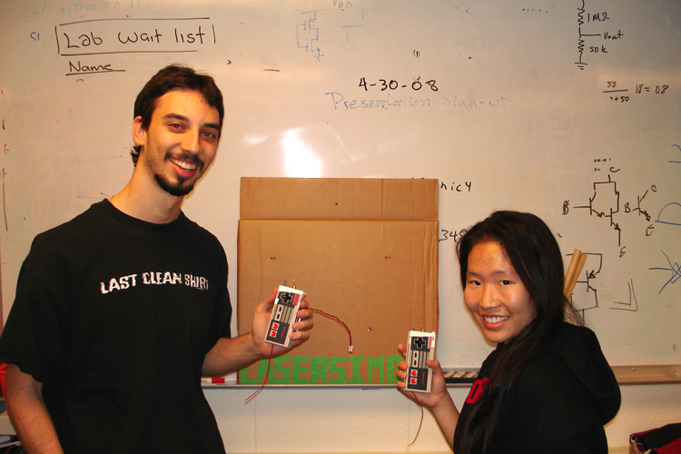
Cathy Chen (cc464)
Adam Shapiro(ams348)
Project Design
Inspiration | Safety | System Overview | Radio Communications | Return to Top
Inspiration
Our project was first inspired by our shared enjoyment of classic laser tag. We initially started out with a game in mind that entailed playing two player laser tag with remote-controlled helium blimps. Due to a number of logistical issues that came up while in the process of implementing our idea including difficulty providing necessary lift and an inability to produce adequate control over the blimps against inherent air currents indoors, we were forced to reformulate and thus LaserSimon was born. LaserSimon allowed us to use our existing radio control platform (described below) and materials in a more easily realizable setting.
Standards and Trademarks
We utilized a commercially available laser pointer compliant with class IIIa laser power and safety specifications.It also complies with
21 CFR of the Center for Devices and Radiological Health (CDRH).
In the United States, OHSA and ANSI standards govern laser safety and personal protective equipment (PPE).
Moreover, the IEC 825 standard defines the maximum exposure limits of lasers and LEDs. The ANSI Z136-1 standard
addresses the engineering and procedural controls necessary when using class IIIa lasers.
Compliance with these safety standards is crucial for the safe and successful development of the laser game and therefore
were followed closely.
Our inspiration: Simon
Photo Credit: wikipedia.com
Additionally, the project utilizes RF transcievers to communicate between components. The transceivers operate in the
433 MHz UHF control band devoted to amateur radio. As such, they were required to be compliant with FCC Part 15 governing
unlicensed RF devices. FCC Part 15 includes important information about RF interference and radio transmission power.
Lastly, Simon is a registered trademark of the Milton Bradley Company, a division of Hasbro, Inc. Although the premise of our
game is similar, it is unlikely that a laser pointer system would be confused with the original touch game seen at right. Considering that the project is used as a Culminating Design Experience project in the junior year of college and we are not
marketing this game commercially, the name LaserSimon will not be used in the public domain.
Safety
Safety of those in the lab is of utmost importance. The two devices that pose the greatest health
hazards were the laser pointers and the RF transcievers. Throughout the building and testing of
the controllers, we were careful to ensure that the lasers' maximum permissible exposure (MPE)
stayed within healthy limits. The lasers we used came with a danger warning which stated maximum
output was <5mW, classifying the laser as a Class IIIA Laser Product. This implied that the
radiation of the laser bouncing off the SimonBoard was safe to view, but that one should avoid
looking directly into the beam of the laser. The output of our laser was stated to be 650nm +/- 10 nm,
which implies again that, at that power level, the beam should not be looked at directly.
During our lab session, we ensured everyone's safety by only shooting the laser at a wall from a short
distance. While the radiation off the wall was safe for everyone to look at, we were close enough to the
wall that no on would accidently walk into the path of the laser beam and be exposed to direct radiation
from the laser. Additionally, we ensured the laser standards including OSHA's and IEC 825, which defines
the maximum exposure limits of lasers, were followed.
The other main health concern was RF transmissions. According to their webside, the Federal Communication
Commission states that "The FCC is required by the National Environmental Policy Act of 1969 to evaluate
the effect of emissions from FCC-regulated transmitters on the quality of the human environment. At the
present time there is no federally-mandated radio frequency (RF) exposure standard. However, several
non-government organizations, such as the American National Standards Institute (ANSI), the Institute of
Electrical and Electronics Engineers, Inc. (IEEE), and the National Council on Radiation Protection and
Measurements (NCRP) have issued recommendations for human exposure to RF electromagnetic fields. The
potential hazards associated with RF electromagnetic fields are discussed in OET Bulletin No. 56, "Questions
and Answers About the Biological Effects and Potential Hazards of Radiofrequency Electromagnetic Fields."
During lab sessions, we made sure to minimize the amount of RF transmissions we were outputting. Additionally,
since the devices we were using were approved by the FCC, we could be sure that they did not broadcast in ways
that were outside the bounds of the law.
Given all of this information, we can deam that our project is safe for everyday use without additional
safety equipment.
System Overview
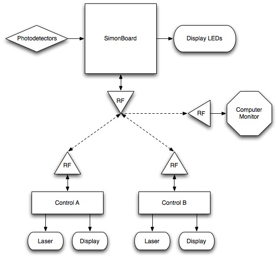
LaserSimon system overview.
LaserSimon is a two player game played with two modified Nintendo NES controllers. The
game has a target board that randomly generates ten levels of patterns, consisting of five
possible hit spots. These spots are indicated on the board by colored LEDs. Hits are detected by
photo diodes located directly to the left of each led. When ready the
players must reset the game. The board then will indicate a pattern for the first player to try.
The player is allowed to aim the laser for one second before each shot. Players trade off, taking turns attempting each of the 10
levels in the game. Scores are calculated based on the number of hits, and the amount
of aim time left over for each successful shot.
At the start of each player's turn, the SimonBoard displays the pattern for the him or her to memorize.
The player then fires at each of targets in succession, taking care to aim as quickly and accurately as possible.
At the end of the game, the winner is displayed on the board, the controllers and the computer interface that
constantly monitors all game activity via a wireless link.
This project fulfilled all our aims of a final project in ECE 4760. We wanted a project that would have
a very tangible visual component, user interaction with the microcontroller, and a fairly involved
communication protocol. It was important to the group that the project be one that did not only involve
software, but rather an interactive game, or game like system. LaserSimon accomplishes this while also
reminding us of the carefree days of childhood.
Radio Communications
Because of the nature of the game, we required a relatively reliable radio communications
link between the players and the SimonBoard. Not only did the link have to be reliable
between a given player and the SimonBoard, each of the four devices
comprising the game (the two controllers, the SimonBoard, and the monitoring computer) needed to be able to
communicate amongst each other with varying degrees of message transmission verification.
We decided to use the Radiometrix BiM2A FM radio transceivers for two reasons. First, the
modules are frequency-shift encoded, and thus require significantly less work in encoding
the data stream to maintain signal reception. The advent of frequency-shift also meant
very simple configuration of the modules - they essentially became a drop-in serial
replacement (with modest configuration and control). Second, unlike their predecessor the
BiM2, the BiM2A modules are capable of operating on an extremely wide voltage range
(2.9V-16V). This was essential for us as, to reduce weight and maintain buoyancy with a
helium balloon we decided to use a single 3.7V lithium-polymer battery cell, and were not
able to provide the usual 5V to our circuits.
Implementation
The Controller | The SimonBoard | Messages & Addressing | Radio Communications | Return to Top
The Controller
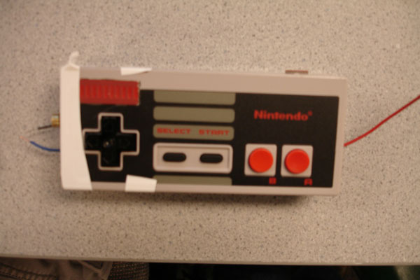
The Controller - together
For nostalgia's sake, we decided to use original Nintendo NES Controllers in the making of
LaserSimon. The controller consists of a single ATmega48, an LED bar graph to provide
feedback to the player, and a BiM2A radio module. The NES controller also houses the player's
laser.
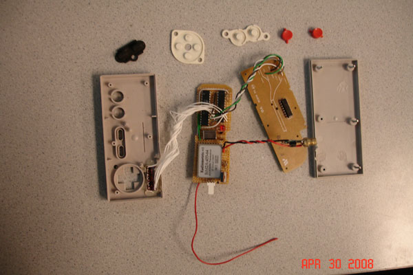
The Controller - apart, with bottons, original NES circuit and our ATmega48, LED driver, LED bar graph, laser, and BiM2A radio transciever
The components were fit into the controller - the controller had to be modified to provide enough room for the circuitry and wiring - and wired to the original controller circuit board. The controller is capable of displaying a number of messages via the LED bar graph. It can inform the user of laser hits/misses, wins/losses, and game resets.
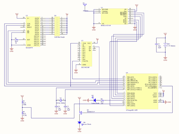
Controller schematics
The SimonBoard
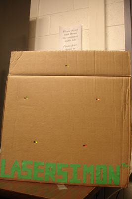
The SimonBoard - front view
The SimonBoard is comprised of an 18"x18" cardboard surface with LEDs and photodiodes attached
to it. All these components were connected to a single ATmega48PV. At the start of the game,
the SimonBoard randomly generates a sequence for the player to repeat. This sequence is directly
mapped to LEDs on the SimonBoard.
At the begining of each level, the SimonBoard flashes the leds in the generated sequence, and then
sets the target as the first LED in the sequence. It broadcasts both a level change message and a
player change message to the two controllers to initialize the level firing order.
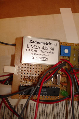
The SimonBoard cicuit - with BiM2A transciever, LEDs, photodiodes, and ATmega48 micro.
Upon receiving a fire report from the currently active controller, the SimonBoard determines whether the player
hit or missed by checking the appropriate photodiode. The result is sent to the controller and
monitoring computer, and the target is moved to the next in the sequence. At end of each player's
turn (when he or she completes the last firing attempt) the current player variable switches and the
new player is broadcast to the cotnrollers. If both players have finished attempts at the level, the
current level is incremented and the controllers are notified.
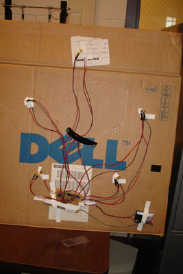
The SimonBoard - back view
The game continues until both players have attempted all ten levels. After the second player completes
his or her attempt at the sequence in level ten, the game ends and scores are calculated. The board then
flashes the LEDs in a pattern indicating the winner. It also broadcasts the information to the controllers
and the monitoring computer for display.
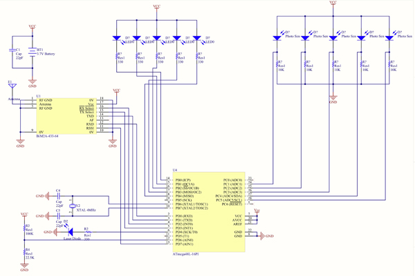
Game controller schematics
Messages & Addressing
| Device Type | Tag | Address |
|---|---|---|
| Control | A | 0x06 (0b0110) |
| Control | B | 0x05 (0b0101) |
| SimonBoard | 0x08 (0b1000) | |
| Broadcast | 0xFF | |
| Null | 0x00 |
Device addresses were computed by bitmasking two criterion: the device type (board or control) and the device tag (A or B) for controls. The encoding scheme was picked such that distinguishing between controls would be quick and simple to do. Device addresses are listed above. The addressing system also includes a broadcast address to which any device may send a message that will be received at all nodes. Broadcasted messages are not acknowledged by any device. Any message sent to the NULL address is discarded.
| Type | ID | Source | Destination | Payload | Event |
|---|---|---|---|---|---|
| Hit Report | 0x01 | SimonBoard | Controller <A,B> | Hit/Miss [0x00/0x01] (1B) | Laser Hit & Fire Pending |
| Fire | 0x02 | Controller <A,B> | SimonBoard | Empty | User Request |
| Reset | 0x03 | Control <A,B> | Broadcast | Empty | User Request |
| Game Over | 0x04 | SimonBoard | Broadcast | Empty | Level 10 Complete |
| Player Change | 0x05 | SimonBoard | Controller <A,B> | Empty | Completion of Turn |
| Level Change | 0x06 | SimonBoard | Controller <A,B> | Current Level (1-10) | Player 2 Level Complete |
The table above lists all of the messages sent from the devices. Some messages are directional, intended only for a single device, while others are broadcast to all devices. These messages carry more pertinent game information such as the reporting of a hit by a particular blimp, and are processed by all devices. The figure below depicts these messages graphically.
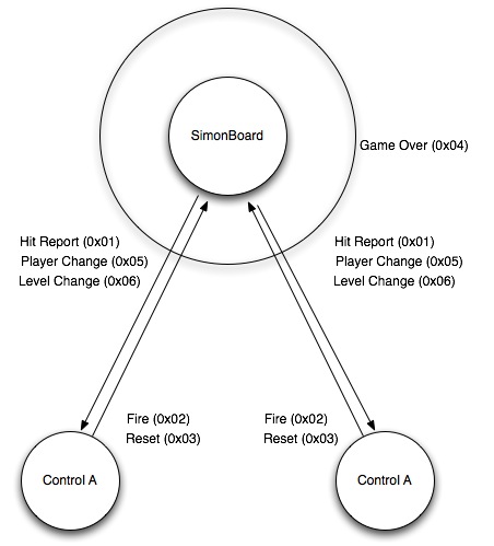
Messaging structure.
Radio Communications
Because the BiM2A modules are half-duplex, we needed to devise a handshaking scheme that would allow us to send information from one device to another at a decent rate, but would also maintain message integrity in the case of interference or collisions. In addition, we required all four devices to be able to address any given device individually, or broadcast a message to everyone. These constraints produced the following requirements:
- Two-way message addressing with broadcast capabilities.
- Message checksum verification.
- Length mismatch checking.
- ACK/NACK handshaking with optional retransmit capability.
- Priority messaging.
- Multi-message buffering.
Message Header
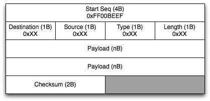
Message structure and formatting.
The message header consists of 4 start bytes, 1 destination address, 1 source address, a 1 byte message type indicator (as shown in the table below), a 1 byte payload length n, an payload of n byte(s), and a 2 byte checksum value. The image above shows the message format as used in the protocol.
| Message Type | ID |
|---|---|
| Data | 0x00 |
| Acknowledged (ACK) | 0x01 |
| Not Acknowledged (NACK) | 0x02 |
Receive (RX)
Message reception uses a simple interrupt-driven circular buffer scheme. As bytes are received
via the USART from the radio transceiver, they are checked to a pre-determined message start
sequence. This start sequence is critical and must be of sufficient length to synchronize the
reception protocol and uniquely distinguish between a valid start-of-message and noise. One
issue with radio transceivers is that they inherently pick up noise when there is no transmitter
on the channel, as they internally raise their reception bias voltage threshold in order to search
for a transmission. If the message start sequence is too short it is entirely possible for random
noise to appear as a valid message which could be catastrophic as the subsequent data would not
possess necessary header information for processing the message. In practice we found that a
sequence of 2 bytes was not sufficient to uniquely distinguish messages, and so we employed a
4 byte start sequence for every message.
After the start sequence is received the message is decoded, including the payload length, until
the entire message has been received. A byte timer is reset upon reception of each successive byte
in order to check for message length errors. If a byte is not received after a set period of time,
the transmission is deemed complete and the message is flagged with a length error.
When the message has finished transmitting its destination address is checked - the message must
be addressed to the local device, or sent as a broadcast - and a checksum is calculated from the
received payload and compared to the transmitted checksum for data verification. If all tests are
passed, the message is flagged as ready for use.
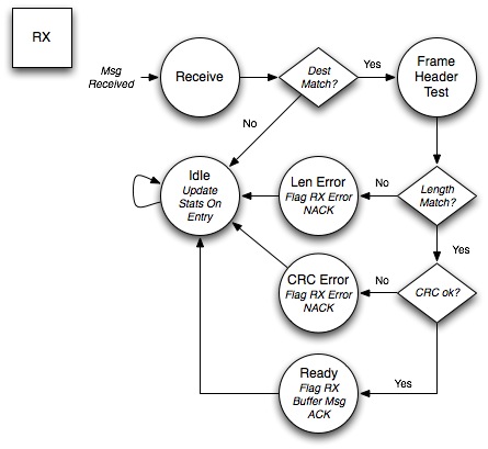
Radio reception verification state machine.
We used the above state machine to verify that messages read were valid before informing the program of their arrival. Any and all errors were recorded such that the program could respond accordingly if desired.
Transmit (TX)
Message transmission is somewhat complicated in that it needs to handle multiple queued messages,
as well as priority messages used for handshaking of received messages. When the program initiates
a transmission, the message is packed with an appropriate header and queued for transmit. Once the
system idles, the transmission state machine takes care of locating any queued messages and starting
their transmission in first-come, first-served order.
Messages may be sent with an optional ability to retransmit upon failure. All directed messages wait
for an acknowledgement from the recipient for a set amount of time, and are flagged as a failures if
such acknowlegements do not arrive, or if they are non-acknowleged (NACKed) by the destination device,
indicating an improper reception. If the message was sent with retransmit enabled, a timer is started
and the system enters an idle state. The timer wakes the system up after a retransmit timeout period,
at which time the message transmission begins again. The state machine below describes the way in which
normal messages are transmitted.
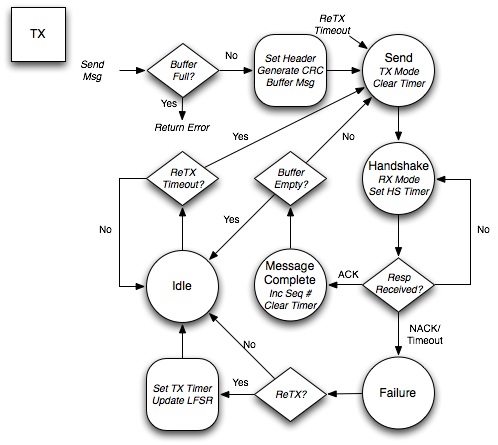
Radio transmission control state machine.
If a priority message is queued, it will enter the transmission flow before any pending messages in the buffer. If a message is currently being sent, the priorty message will be held until the message has completed. When the priority message has completed transmission, the system will automatically resume normal operations. Only one priorty message may be queued at any given time (priority messages do not have an option to retransmit).
Results
We tested each component by itself, and when sent the correct message via a serial input
on the SDK500, each chip behaved as expected. We then determined that the radio transciever
on each element in the design (the controllers and the SimonBoard) functioned correctly.
Then, we moved the micros to the controller and SimonBoard Hardware to begin testing the
hardware with the radio communication.
In testing the project, we ran into a number of errors and complications stemming from the
radio communication. The first issue was that the recievers were very susceptible to noise
in the area. We first realized this when we began experiencing transmission errors during
a nearby event that used a considerable number of wireless devices. The radio receive protocol
required that we use a receive interrupt on the USART, and the nature of the noise was such
that the microcontroller was getting interrupted with great frequency, making it difficult,
if not impossible, to receive any valid messages. We remedied this by using an analog comparator
to enable the receive interrupt when the RSSI (signal strength indicator) signal from the
transceiver had passed a reference voltage tuned to the background noise threshold.
Excessive noise was still an issue after including the RSSI triggering in that occasionally
noise would affect packet data after a valid message start sequence had been received. If
this happened to change the packet length byte, it was entirely possible for the system to
overflow its receive buffers very quickly. We protected against this simply by double checking
the data position to the maximum buffer length in the receive interrupt, and flagging a length
error if the length was ever exceeded.
The problem we could not figure out in the end was a situation in a which retransmited
messages were only retransmitted a (randomly variable) number of times and then mysteriously
stopped transmitting. This was a concern in that excessive radio noise made it very difficult
for the devices to reliably receive messages, and often retransmission was required multiple
times before a message would be received. The potential causes of this were checked and rechecked by both
ourselves, Professor Land, and Adrian Wong, and we were unable to find the issue. We ultimately
were unable to remedy the issue, and it was still evident upon presentation of the project.
Conclusion
Project Conclusions | Ethical and Legal Considerations | Return to Top
Project Conclusions
To future students attempting a blimp project, we would advise that they carefully consider the weight
of each individual component going into the board, and be sure to test that the balloon is capable of
lifting everything that must be lifted well in advance. Calculations of helium lifting strength can only
take you so far. Additionally, we were very concerned about the wind currents due to air circulation within
the rooms in which we needed to operate the blimps, and without adequate motor specifications it was very
difficult for us to factor this into the strength required to maintain control over the blimp; unfortunately
we never reached a point with LaserBlimp where this would become a major concern.
We had three main issues with our design. The use of half-duplex transcievers led to considerably complicated
code over the code required for full-duplex communication. Noise was also big issue in our project and required
a great deal of complexity to overcome. Given another opportunity we would most likely use full-duplex transcievers,
thus decreasing the complexity of our code and allowing for faster transmissions; full-duplex could also potentially
make error correction easier by allowing us to monitor outbound messages in real time.
Because of the complexity of the radio code, we ran out of flash memory on the ATmega48PV, and had to reduce our
code to make it fit onto the micro, sacrificing a number of useful game features for basic functionality. Though
changing to full-duplex radio transcievers would have reduced the size of our code, use of a different micro with
more memory but similar computing power would have helped considerably. The ATmega88, a larger variety of the ATmega48, is one such device.
Please feel free to contact Cathy Chen and/or
Adam Shapiro with any further questions regarding this project.
Ethical and Legal Considerations
Throughout the course of this project we strictly followed the IEEE
Code of Ethics in an effort to ensure the safety of everyone around us. Additionally, we ensured that everyone we interacted with and
recieved input from was correctly credited for ideas and help. Through the course of working on this project, particularly when we decided
to change goals, discussion between the two partners stayed civil and practical. We were realistic when the original idea fell through and
after careful consideration decided to shift project goals.
Legal considerations we had were the use of the Simon registered trademark which we have deemed acceptable within the confides of
the lab. Additionally, we had to comply with all FCC regulations regarding RF broadcasting. Given that the trancievers we are using
are approved by the FCC and follow all applicable codes, standards, and regulations, we in full compliance with the law on this issue
as well. Lastly, use of a class IIIA laser had to adhere to all relivent standards as mentioned above. According to the packaging of
the laser, the laser we are using, which we are using within the voltage and ampere ratings, stated is safe for a class IIIA laser and
additionally follows all reliavent standards, codes, and regulations set by applicable organizations. Thus, all legal considerations are
addressed and determined to be within the limits of the law.
Appendix
Budget | Division of Labor | Acknowledgements and References | The Code | Return to Top
Budget
| Item | Part Number | Source | Unit Price | Quantity | Total Cost |
|---|---|---|---|---|---|
| Micro | ATmega48P/V | atmel.com | Sample | 3 | $0.00 |
| Transceiver | BiM2A-433-64 | radiometrix.com | Sample | 4 | $0.00 |
| Laser | 774 | dealextreme.com | $1.00 | 2 | $2.00 |
| Battery | 1200HP | E-Tec Batteries | Owned | 3 | $0.00 |
| Photo Diode | BPW46 | vishay.com | Sample | 5 | $0.00 |
| LEDs | N/A | ECE476 Lab | $0.00 | 5 | $0.00 |
| DIP Socket | Cornell RoboCup | Surplus | 2 | $0.00 | |
| NES Controller | NES Controller | ebay.com | $7.00 | 2 | $14.00 |
| PC Board | Cornell DARPA | Surplus | 2 | $0.00 | |
| LED Bar Graph | 160-1066-ND | digikey.com | $1.50 | 2 | $3.00 |
| LED Driver | MAX6969ANG | maxim.com | Sample | 2 | $0.00 |
| 4MHz Crystal | ECE 476 Lab | $0.00 | 3 | $0.00 | |
| 22pF Capacitor | Cornell RoboCup | $0.00 | 2 | $0.00 | |
| Total | $19.00 |
Division of Labor
The radio transmitting protocall, the controller code, and the computer interface were written by Adam Shapiro. Additionally,
Adam built the hardware for the controllers and designed and created all circuit schematics.
The orginal blimp hardware board and blimp gondola were built by Cathy Chen. She also started writing blimp code.
When that project failed, she rebuilt the board to become the SimonBoard and wrote the SimonBoard code.
This webpage was formated to Cornell University Visual Identity guidelines
by Adam Shapiro and created by both Cathy Chen and Adam Shapiro.
Acknowledgments and References
The only code we used in this project we created during the span of the final project.
We would like to thank ECE 476 TA Adrian Wong for the original idea of LaserBlimp. Our original idea of the Simon like game was a last minute attempt to reuse the most of our already built circuits when we realized that the blimp would not lift the circuit we had built (four days before the due date!) . Though we made up the rules of the game on our own, and created the game accordingly from there, we were inspired by the Milton Bradley game Simon.
Special thanks and gratitute to Professor Bruce Land for his long hours in the lab and for all his help. Additional thanks to Adrian Wong for the original idea of LaserBlimp. We would also like to thank all the ECE 476 TAs for their long extra office hours in the lab. Thanks to Radiometrix for their donation of four radio trancievers. In addition, we would like to thank Atmel for its microcontroller samples. We would like to thank Cornell's Student Activities Office for its donation of helium though the blimp was not used in the end. Much gratitute to Tom McCann of Sky Hooks and Rigging for his help in researching motors and propellers for the original project.
Datasheets
Atmel Mega 48
Led Driver
Radiometrix Trancievers
The Code
Our code was initially written in CodeVision, however it was recently converted to AVR GCC for further portability. It is available here in both versions. It has also been zipped for easy downloading.