Wiimote
Crane
Andrew Courtney(apc27)
Wan Ling Yih(wy47)
Table
of Contents
VI.
Appendixes
We used the Wiimote’s IR tracking capability and Bluetooth to wirelessly control a robotic crane arm. The Wiimote is a powerful gadget and we wanted to build a new hack with it. Our crane is composed of three servo motors, one of which is connected to a gripper. The servos are controlled by PWM signals sent by the Mega32 MCU, and these signals are generated from parsing the received IR data from a serial connection with a Macbook wirelessly connected through Bluetooth to the Wiimote.
Motivation
After watching some of Johnny Chung Lee’s videos on Wiimote hacks(http://www.cs.cmu.edu/~johnny/projects/wii/), especially the infrared tracking video, we were inspired to create our own Wiimote application. Our first idea was to track points using two Wiimotes in 3-d, but the difficulty of getting just one Wiimote to work scratched that idea. We decided to use the remote to track infrared points and use this data to control a crane composed of three servos with a gripper.
Background
Math
There wasn’t any extremely challenging math involved in our project. We needed to understand how the Wii’s IR camera worked and also needed to be good at PWM signals for the servo motors. We also needed some basic circuit design skills for building the LED array. The explanations for these concepts come up in the later sections of this report.
Logical
Structure
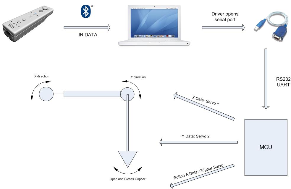
Figure 1:
Project Diagram
Hardware/Software
tradeoffs
We needed to generate three PWM signals to control the three servo motors. Only two timers on the Mega32 have PWM capabilities (Timer0/Timer2), so we had to manually generate a PWM signal, which sacrificed some accuracy on our timing. Fortunately the servo doesn’t have to be in a precise position for the crane to work, it only has to be roughly controllable.
Relation
to Standards and Intellectual Property
Our project uses the Bluetooth wireless protocol, which is a built-in feature of the Macbook as well as the Wiimote. The Wiimote was designed by Nintendo, though I haven’t found a patent for the Wiimote itself. We do not intend to commercialize our design so this should not be an issue.
Software
Timers
and PWM
We use three timers to set up the PWM signals used in this project. For timer0 and timer2 we run them on full PWM mode with the prescalar set so they run at clk/1024 = 15.625 KHz. Since they are 8-bit timers they overflow with a period of roughly 16ms. We use this period as one PWM cycle and set OCR0 (or OCR2) to vary the width of the pulse. Timer 1 is set to clear on match mode running at 5KHz. In the timer1 compare match interrupt we set up a custom PWM signal to control the gripper servo. The hardest part of setting up the PWM signals was configuring the servos to be in the correct position and varying the pulses to the right degree to move the servo arm where we wanted it.
Parsing/Porting
Wiimote Data
The Wiimote has two types
of sensors: accelerometers and an infrared camera. With these two devices, the players
communicate with the main console via Bluetooth. In our project we use the
infrared camera and its ability to track an infrared source’s x-y
coordinates within the Wiimote’s plane of
view. A Wiimote
view is 41° in x direction and 31° in y direction.
Communicating between the Wiimote
and the MCU is established through the USB serial RS232 input using the serial
UART receive/transmit feature on the Mega32. Here we only use the receive
portion on the microcontroller to receive the Wiimote’s
IR data from a MacBook. We use the MacBook
to port the Wiimote’s IR data since MacBook has Bluetooth functionality built in, and by
downloading a Wiimote driver on the MacBook (open
source driver DarwiinRemote), we extract the IR data
from the Wiimote and send it through the USB-to-serial
connection
Within the DarwiinRemote
application, the package includes a WiiRemote.framework,
which is the binary for the WiiRemote library on the
Macintosh. After downloading the application and the WiiRemoteFramework
library source code from Source forge, with the XCode
IDE we are able to locate where IR data and button status data are in the
source code, open a serial port by calling the open serial port C code acquired
from the Apple Developer website, and write data to the USB to serial connection
located on the dev port of the MacBook hardware. Within the DarwiinRemote
application, the x-coordinate IR data ranges from 0 to 1023 and y-coordinate IR
data ranges from 0 to 767. If the WiiRemote sees no
IR source, then the x and y IR data values are both 1023. These values are
important for servo calibration control. The serial port code serialPort.c includes various functions, but the
main functions we used were serialPort (int x, int y), OpenSerial (bsdPath) (internally
called by serialPort), and InitializeModem (int x, int y, int pressed). When
opening a serial port, the user can specify if the port is open for transmit or
receive, blocking or nonblocking, and set for the
existence of a control terminal. Here we set up the port as write only (since
we are only sending data to MCU), nonblocking, and no
controlling terminal. The serial port C code lets the user
set the baud rate, data packet size, number of parity bits, and number of stop
bits. We configure this to our
regular hyper terminal settings at 9600 baud, 8 data bits, no parity bits, 1
stop bit, and no flow control.
For porting the x, y, and button data to the serial
port, we first convert the x and y data from integer to string using sprintf and store them in buffers. For the A button, there is a defined
array called buttonState,
along with a define macro WiiRemoteAButton, where WiiRemoteAButton acts as a index into the buttonState array and will be set to predefined macro value YES if button is pressed. We define a
local variable integer pressed to be
set high whenever buttonState[WiiRemoteAButton] equals to YES within the WiiRemoteFramework source
code. We then write this value to a string buffer and send the button data
along with the x and y IR data every time we communicate with the serial
port. Finally to terminate every
set of data sent, we send a carriage return (“\r”) to the serial
port so the MCU will know when a set of data completes transmission.
On the MCU side, we initialize the serial UART
RX/TX capability in the initialize() function by setting UBRRL and UCSRB to
the appropriate baud rate and enable serial USB receive. On the hardware side,
we have to connect jumper RX/TX to pin D.0 and pin D.1 to enable receive. The
receive interrupt will then be triggered after every incoming string character.
The UDR_RXC interrupt will be called, and within the interrupt we place the
data in its respective buffer array (x, y, or button data).
Using
the IR data
An extremely challenging part of our project was figuring out how to translate the XY coordinates from the Wiimote to pulse widths for the servo motors. For the x-coordinates we set up a system where every 50 pixel range of points corresponded to one pulse width and we limited the motion of the servo to a change of one “pulse width” or one value of OCR0 per call of the compare_x function. For the y-coordinates we segmented the points into three positions, one for upwards movement, one to stay stationary, and one for downwards movement. The gripper servo has a specific sequence of pulses that is triggered each time the A button on the Wiimote is pressed. The gripper pulses slowly open and then close the gripper.
Hardware
Custom
Board
We built the custom Mega32 board exactly as described on the ECE 476 website (http://www.nbb.cornell.edu/neurobio/land/PROJECTS/Protoboard476/index.html).

Figure 2
Custom Mega32 Board
LED
Arrays
The hardware used for this project wasn’t extremely complicated, but required several parts that have to work together. To provide infrared light that the Wiimote could track we built several IR led arrays. In the appendix there is a schematic for an LED array. The array has a 12V source connected in series with a 75 Ohm resistor and 8 LEDs. Each LED is rated for a forward voltage drop of 1.2V so 8 LEDs is a total drop of 9.6V. With a 12V source there should be a 2.4V drop over the 75 Ohm resistor, drawing 32mA of current. The LEDs are rated for 20mA with a maximum of 50mA so this array configuration should be fine.
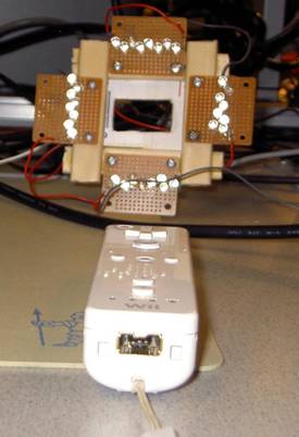
Figure 3 LED Array and Wiimote
Optoisolator Circuit
Since we were using noisy motors we had to make sure the ground paths for the MCU and servo were not shared. Similar to Lab 3 we used 4N35 optoisolators to separate the two sides of the circuit. On the MCU side of the circuit we have a 330 Ohm resistor connected to the diode on the 4N35. On the motor side the base of the transistor is connected to ground through a 1MOhm resistor, the emitter is connected to the control line of the servo as well as to ground through a 10KOhm resistor. The collector is connected to 5V Vcc (separate from MCU).
Mechanical
Design
To build the crane we mounted the arm servo to a piece of wood for a base and nailed a another piece of wood to the horn of the servo for the rotating arm. At the end of the arm is the continuous rotation servo that raises and lowers the gripper. We tied the gripper hardware to the horn of this servo with some string. The gripper as well as the gripper control servo hangs from the bottom of the string.
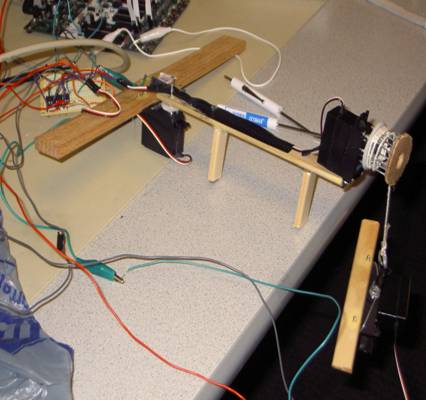
Figure 4 Crane Hardware

Figure 5 Gripper with Servo
Servo
PWM control
A servo motor is controlled by a pulse-width modulated signal (PWM) that tells its arm which position to be in. Generating these signals is fairly straightforward using the timers on the Mega32, though we had to ensure all three of our PWM signals were accurately timed. Below is a basic diagram of a PWM signal. There is a shorter pulse of voltage Vcc at the start of the pulse while the total pulse has a period of 20ms (though this has some tolerance). For two of our servos we used a 16 ms pulse, for the other we used a 20ms pulse. The difference was only due to the timers we used to set up the pulses.
Figure 6:
PWM Signal
Modifying
a servo for continuous rotation
To raise and lower the gripper we needed a servo that could rotate continuously. The standard servos we ordered could only rotate about 270 degrees, so we had to take one apart and do some modifications. This required learning a little bit more about how servo motors work and getting our hands dirty. The first step was opening the servo case to expose the gear train. One of the gears had a notch at the bottom which prevented the servo from rotating 360 degrees, so first we cut out the notch.
The servo has a potentiometer that is part of a feedback loop with the motor to control the servo arm’s position. The position of the potentiometer is compared to the pulse width arriving on the control line and the motor rotates the potentiometer until its resistance matches with a value derived based on the pulse width. We had to disengage the potentiometer from the motor to break the feedback loop. There was a washer in the base of the gear sitting over the potentiometer that we removed which allowed the gear to spin without moving the potentiometer. Next we calibrated the servo to stop spinning with a constant width PWM by adjusting the potentiometer position. Now that we had a reference pulse width to stop the servo, making the pulse slightly wider would make the servo spin continuously in one direction, and making the pulse narrower spins it the other way. The potential problems with this modification are:
A) If you break the servo somehow – you just voided any warranty you had by modifying it.
B) You no longer know where the servo is based on the pulse width, the servo no longer has feedback to stay in one constant position.
C) If the potentiometer slips or you want to use a different default pulse width, you need to open up the servo again and recalibrate it with a new pulse.
However for our application we needed the servo to do this and didn’t want to order a new servo so we accepted these tradeoffs.
Stuff that didn’t work
Our final code uses the fast PWM mode of timer0 and timer2 and uses timer1 to set up a manual pulse inside its compare match interrupt. In our first version we tried to manually create pulses for all three servos. We called functions from main that set output ports to 1 or 0 based on some software counters. This plan worked at first until we generated all three PWM signals, at which point the code wasn’t fast enough to accurately create all the signals which caused the servos to jitter. First we tried optimizing the code to make it faster, but finally we switched to hardware PWM control which worked much better.
We tried a number of software schemes for controlling the servos based on the coordinates being received. The trickiest servo to control was the continuous rotation servo, because its internal potentiometer was disengaged the servo’s feedback loop doesn’t function and the servo position has to be controlled in software. Instead of spinning the servo for different amounts of time depending on the IR data’s y-coordinates, we created three regions of y-data. If the y-data was near the top of the IR camera’s range, the servo pulls the rope up - in the middle and the servo stops – near the bottom and the rope lowers. This gave much better control than the other methods we tried.
We managed to build a Wiimote-controllable crane that can rotate from side to side, raise and lower a gripper, and pick up small objects. The Wiimote control works, though it can be really sensitive so using it requires some practice. The continuous rotation servo turns smoothly and the gripper servo works well. The rotating arm servo’s movement is still somewhat choppy however. Overall the servo crane works alright but is a little bit too sensitive to small movements by the Wiimote.
Safety
The user interface for our project is the Wiimote, which is a common device and extremely safe(unless you throw it at your television). The crane arm could potentially swing fast enough to pinch a finger and the gripper servo can grab pretty hard, but these problems can be mitigated by moving the crane assembly away from the user or encasing it behind glass(like the candy cranes at a mall).
Interference
with other designs
Our project is unlikely to interfere with nearby projects. The Wiimote uses Bluetooth to communicate with the Macbook. Bluetooth is unlikely to interfere with other devices as it quickly hops between frequencies around 2.4 GHz rather than broadcasting at a single frequency.
Results
versus expectations
Our first idea for a project was to track 3d points with two Wiimotes, and we eventually changed this to one Wiimote after having trouble getting the remote to work correctly. Once we got the remote working and sending data to the MCU we had to come up with an application of the IR tracking. Building a crane seemed like a good combination of software and hardware as well as a device that would be fun to play around with. The crane itself works well, though with some more time we could build one with a stronger frame and more aesthetics.
We would like to thank
IP
Considerations
Our project uses Nintendo’s Wiimote and is inspired by Johnny Chung Lee’s Wiimote hacks. The basic IR tracking of our project is similar to Lee’s “Tracking Your Fingers With The Wiimote” project, though we use the Wiimote in a slightly different fashion by moving the remote itself rather than reflecting IR light off our fingers as in his video.
Relationship
to Patents/Standards
This project has been designed in close adherence to the IEEE Code of Ethics. Safety considerations have been a primary concern and we believe that we have disclosed any risks inherent to our design as well as producing a project unlikely to cause harm. The project uses low voltages for its electrical components and as long as the crane is positioned correctly our user interface is perfectly safe. We believe that we have adequately credited the contributions of those who motivated and helped with our project. Intellectual property issues have been disclosed and are not of primary concern as we have intent to patent or commercialize our design.
Legal
Considerations
Since we are not intending on profiting from this project intellectual property issues should not be much of a concern. Bluetooth is not a high power wireless protocol and not a problem for interference with other devices.
MCU
Code
#include <Mega32.h>
#include <delay.h>
#include <math.h>
#include <stdio.h>
#include <values.h>
#include <stdlib.h>
#include <string.h>
#define t1 2
#define FILTERSIZE 5
unsigned char r_index,
r_buffer_x[5], r_buffer_y[5],
r_buffer_button[1], r_ready,
r_char;
unsigned int
time1;
unsigned char read_buffer[16];
unsigned int x_val, y_val, button_a,
last_x_val, last_y_val, badValueCount;
unsigned char turn_right,
turn_left, grab_count;
int ropePWMctrl, gripPWMctrl, armPWMctrl, PWMadd;
unsigned int yPosArray[5], xPosArray[5];
int yAve, xAve,
last_y_ave, last_x_ave;
unsigned char PWM_cycle,
num_grab_cycles, grab_pulse;
//function prototypes
void processIRData(void);
void PWMctrler(void);
void puts_int(void);
void gets_int(void);
void initialize(void);
void compare_x
(void);
void compare_y
(void);
//timer2 overflow
interrupt, decrements time2 and resets timer2 for PWM control
//this interrupt is
called roughly once every 16ms
interrupt [TIM2_OVF] void
timer2_overflow(void)
begin
//if (time2>0) time2--;
end
//timer1 cmp-match is called at 5KHz
interrupt [TIM1_COMPA] void
timer1_cmpmatch(void)
begin
//this timer controls the grabber
servo when button A is pressed on the Wii remote
if
(grab_count >0)
begin
//manual PWM signal
if (PWM_cycle == 2) PORTB.2 = 1;
if (PWM_cycle == grab_pulse) PORTB.2 = 0;
//each cycle is 20ms so 100 calls of this function at 5KHz
if (PWM_cycle == 100)
begin
grab_count--;
PWM_cycle = 0; //reset PWM pulse
num_grab_cycles++;
end
if (num_grab_cycles ==10) //send
10 pulses at one length before changing the width
begin
grab_pulse--;
//controls pulse width
num_grab_cycles = 0;
end
PWM_cycle++;
end
end
//timer 1 is running at
16MHz/1024 or 15625 Hz and timer0 is 8bits so this is called roughly once every
16ms
interrupt [TIM0_OVF] void
timer0_overflow(void)
begin
if (time1
>0) time1--;
end
//USART receive complete
interrupt
interrupt [USART_RXC] void REC(void)
begin
r_char
= UDR;
if
(r_char != '\r')
begin
//parse x and y data
if(r_index<4)
r_buffer_x[r_index++]
= r_char;
else if (r_index
>=4 && r_index < 8)
begin
PORTB.4 = ~PORTB.4;
r_buffer_y[r_index-4] = r_char;
r_index++;
end
else
begin
r_buffer_button[0] = r_char;
end
end
else //end of line
begin
putchar('\n'); //won't
block
r_ready = 1; //ready to process string
UCSRB.7 = 0; //disable
RX complete interrupt
end
end //end USART.RXC intr
//processIRData
takes the incoming IR data, filters it, and uses it to set servo positions
void processIRData(void)
begin
int
i;
int
k;
time1 = t1;
if (r_ready)
begin
last_x_val = x_val;
if (y_val
!= 1023) last_y_val = y_val;
last_y_ave = yAve;
if (y_val
== 1023 || x_val == 1023) badValueCount
= 1;
else
begin
if (badValueCount>0) badValueCount--;
//update x and y
position arrays
for (k = 0; k<FILTERSIZE-1; k++)
begin
yPosArray[k+1]
= yPosArray[k];
xPosArray[k+1]
= xPosArray[k];
end
yPosArray[0]
= y_val;
xPosArray[0]
= x_val;
end
//calculate position averages of the last 5 readings
for (k = 0; k<FILTERSIZE; k++)
begin
yAve += yPosArray[k];
xAve += xPosArray[k];
end
yAve = yAve/FILTERSIZE;
xAve = xAve/FILTERSIZE;
//get new x, y, and button readings
x_val = atoi(r_buffer_x);
y_val = atoi(r_buffer_y);
button_a = atoi(r_buffer_button);
//if
the user presses button A on the remote start contracting the grabber
if (button_a)
begin
grab_count = 100;
grab_pulse = 12;
end
else if (badValueCount == 0)
begin
compare_y();
compare_x();
end
gets_int();
end
end
void PWMctrler(void)
begin
//rotating
servo controls, high being 30 won't turn it at all,
if (turn_left)
begin
OCR2 = 28;
end
else if (turn_right)
begin
OCR2 = 32;
end
else
begin
OCR2 = 30;
end
//manual
control of pulse width via STK buttons
if (PINA.2==0)
begin
OCR0 += PWMadd;
OCR2 += PWMadd;
PWMadd = 0;
end
if (PINA.1==0)
begin
PWMadd = 1;
end
if (PINA.0==0)
begin
PWMadd = -1;
end
end
void compare_x
(void)
begin
//this function uses the average
of the last 5 x points to set a servo position
//x coordinates run
between 0-1023, with 1023 representing no reading
//each range of 50 pixels
is set to a certain servo position by changing a pulse width
//to minimize jerk in the
servo the pulse width is only changed by 1 each time
//this function is called
until the servo has the proper orientation
if (xAve
> 0 && xAve < 50 && OCR0 >
10) OCR0--;
else if (xAve
>= 50 && xAve < 100)
begin
if
(OCR0 > 11) OCR0--;
else
if (OCR0 < 11) OCR0++;
end
else if (xAve
>= 100 && xAve < 150)
begin
if
(OCR0 > 12) OCR0--;
else
if (OCR0 < 12) OCR0++;
end
else if (xAve
>= 150 && xAve < 200)
begin
if
(OCR0 > 13) OCR0--;
else
if (OCR0 < 13) OCR0++;
end
else if (xAve
>= 200 && xAve < 250)
begin
if
(OCR0 > 14) OCR0--;
else
if (OCR0 <14)OCR0++;
end
else if (xAve
>= 250 && xAve < 300)
begin
if
(OCR0 > 15) OCR0--;
else
if (OCR0 <15)OCR0++;
end
else if (xAve
>= 300 && xAve < 350)
begin
if
(OCR0 > 16) OCR0--;
else
if (OCR0 <16)OCR0++;
end
else if (xAve
>= 350 && xAve < 400)
begin
if
(OCR0 > 17) OCR0--;
else
if (OCR0 <17)OCR0++;
end
else if (xAve
>= 400 && xAve < 450)
begin
if
(OCR0 > 18) OCR0--;
else
if (OCR0 <18)OCR0++;
end
else if (xAve
>= 450 && xAve < 500)
begin
if
(OCR0 > 19) OCR0--;
else
if (OCR0 <19)OCR0++;
end
else if (xAve
>= 500 && xAve < 550)
begin
if
(OCR0 > 20) OCR0--;
else
if (OCR0 <20)OCR0++;
end
else if (xAve
>= 550 && xAve < 600)
begin
if
(OCR0 > 21) OCR0--;
else
if (OCR0 <21)OCR0++;
end
else if (xAve
>= 600 && xAve < 650)
begin
if
(OCR0 > 22) OCR0--;
else
if (OCR0 <22)OCR0++;
end
else if (xAve
>= 650 && xAve < 700)
begin
if
(OCR0 > 23) OCR0--;
else
if (OCR0 <23)OCR0++;
end
else if (xAve
>= 700 && xAve < 750)
begin
if
(OCR0 > 24) OCR0--;
else
if (OCR0 <24)OCR0++;
end
else if (xAve
>= 750 && xAve < 800)
begin
if
(OCR0 > 25) OCR0--;
else
if (OCR0 <25)OCR0++;
end
else if (xAve
>= 800 && xAve < 850)
begin
if
(OCR0 > 26) OCR0--;
else
if (OCR0 <26)OCR0++;
end
else if (xAve
>= 850 && xAve < 900)
begin
if
(OCR0 > 27) OCR0--;
else
if (OCR0 <27)OCR0++;
end
else if (xAve
>= 900 && xAve < 950)
begin
if
(OCR0 > 28) OCR0--;
else
if (OCR0 <28)OCR0++;
end
else if (xAve
>= 950 && xAve < 1000)
begin
if
(OCR0 > 29) OCR0--;
else
if (OCR0 <29)OCR0++;
end
else if (xAve
>=1000 && xAve < 1024)
begin
if
(OCR0 > 30) OCR0--;
else
if (OCR0 <30)OCR0++;
end
end
void compare_y(void)
begin
//the y-values for the IR camera are between 0-787, with 1023 meaning no
reading
//The y-servo has been modified to run continuously and therefore has
only three commands: stop turning, turn CW, and turn CCW
//if y is in the middle of the
range, we stop the servo
//if
y is near the top of the range, we raise the rope
//if
y is near the bottom of the range, we lower the rope
if (y_val == 1023 )
begin
turn_right = 0;
turn_left = 0;
end
else
begin
if (y_val > 475)
begin
turn_right = 1;
turn_left = 0;
end
else if (y_val <
225)
begin
turn_left = 1;
turn_right = 0;
end
else
begin
turn_left = 0;
turn_right = 0;
end
end
end
void gets_int(void)
begin
r_ready = 0;
r_index = 0;
UCSRB.7 = 1; //RX complete
interrupt enable on
end
void main(void)
begin
initialize();
//endless loop
while(1)
begin
if (time1 == 0)
begin
processIRData();
PWMctrler();
end
end //end while
end //end main
void initialize(void)
begin
int
k = 0;
//set I/O direction for port pins
DDRB = 0xff;
DDRD.7 = 1;
DDRC.7 = 1;
DDRC.0 = 1;
DDRC.2 = 1;
PORTB = 0xf0;
PORTC.7 = 0b1;
UCSRB = 0x90; //enables serial receive UCSRB =
0b10010000
UBRRL = 103; //set baud rate 9600
//initialize starting PWM widths
OCR0 = 20; //PINB.3
TIMSK = 0b01010001;
//enables timer 2 overflow intr, timer 1 cmp-match, timer 0 overflow interrupt
TCCR2 = 0b01101111;
//bits 3 and 6 enable fast-pwm mode, bits 4
and 5 set OC2 at top and clear at OCR2, prescalar 111
is CLK/1024
ASSR = ASSR & 0b11110111;
OCR2 = 30; //PIND.7
TCCR1A = 0x00;
TCCR1B = 0b00001011; //sets up timer1
for clear on match counting, with presclar
clk/64=250KHz
OCR1A = 50;
//helps to set up 1/5 ms time base
TCCR0 = 0b01101101; //turn on fast PWM mode, set OC0
bit at TOP and clear at match
PWMadd = 0;
time1 = t1;
x_val = 1023;
y_val = 1023;
badValueCount
= 0;
last_x_val =
1023;
last_y_val =
1023;
last_y_ave =
1023;
last_x_ave =
1023;
turn_right =
0;
turn_left = 0;
xAve
= 1023;
yAve
= 1023;
grab_count =
0;
PWM_cycle = 0;
num_grab_cycles
= 0;
grab_pulse =
14;
for (k=0;
k<FILTERSIZE; k++)
begin
//initialize x/y arrays to
"no reading" value of 1023
yPosArray[k] = 1023;
xPosArray[k] = 1023;
end
//turn on interrupts
#asm("sei");
r_ready = 1;
gets_int();
end
Snippets of Code modified for Wii connection
- (void) handleIRData:(unsigned
char *) dp length:(size_t) dataLength
{
// NSLog(@"Handling IR Data for 0x%00x", dp[1]);
int
i = 0;
//int* test
= malloc(sizeof int *);
char pressed
= 0;
//int blah
=0;
if (dp[1] == 0x33) { // 12 IR bytes
int startByte
= 0;
for(i=0 ; i
< 4 ; i++) {
startByte = 7 + 3 * i;
irData[i].x = (dp[startByte
+0] | ((dp[startByte +2]
& 0x30) << 4)) & 0x3FF;
irData[i].y = (dp[startByte
+1] | ((dp[startByte +2]
& 0xC0) << 2)) & 0x3FF;
irData[i].s = dp[startByte +2] & 0x0F;
}
}
else { // 10 IR bytes
int shift = (dp[1]
== 0x36) ? 4 : 7;
int startByte
= 0;
int i;
for (i=0; i
< 2; i++) {
startByte = shift + 5 * i;
irData[2*i].x = (dp[startByte
+0] | ((dp[startByte +2]
& 0x30) << 4)) & 0x3FF;
irData[2*i].y = (dp[startByte
+1] | ((dp[startByte +2]
& 0xC0) << 2)) & 0x3FF;
irData[2*i].s = ((irData[2*i].x == irData[2*i].y) && (irData[2*i].x == 0x3FF)) ? 0x0F : 0x05; //
No size is given in 10 byte report.
irData[(2*i)+1].x = (dp[startByte
+3] | ((dp[startByte +2]
& 0x03) << 8)) & 0x3FF;
irData[(2*i)+1].y = (dp[startByte
+4] | ((dp[startByte +2]
& 0x0C) << 6)) & 0x3FF;
irData[(2*i)+1].s = ((irData[(2*i)+1].x == irData[(2*i)+1].y) && (irData[(2*i)+1].x == 0x3FF)) ? 0x0F : 0x05; //
No size is given in 10 byte report.
}
}
NSLogDebug
(@"IR Data (%i, %i, %i) (%i,
%i, %i) (%i, %i, %i) (%i,
%i, %i)",
irData[0].x, irData[0].y, irData[0].s,
irData[1].x, irData[1].y, irData[1].s,
irData[2].x, irData[2].y, irData[2].s,
irData[3].x, irData[3].y, irData[3].s);
int
p1 = -1;
int
p2 = -1;
// we should modify this loop to take
the points with the lowest s (the brightest ones)
for (i=0 ; i<4 ; i++) {
if (p1 == -1) {
if (irData [i].s
< 0x0F)
p1
= i;
}
else {
if (irData [i].s
< 0x0F) {
p2
= i;
break;
}
}
}
// NSLogDebug (@"p1=%i ;
p2=%i", p1, p2);
double ox, oy;
if ((p1 >
-1) && (p2 > -1)) {
int l = leftPoint;
if (leftPoint == -1) {
switch (orientation) {
case 0: l = (irData[p1].x < irData[p2].x) ? 0 : 1; break;
case 1: l = (irData[p1].y > irData[p2].y) ? 0 : 1; break;
case 2: l = (irData[p1].x > irData[p2].x) ? 0 : 1; break;
case 3: l = (irData[p1].y < irData[p2].y) ? 0 : 1; break;
}
leftPoint = l;
}
int r = 1-l;
double dx = irData[r].x
- irData[l].x;
double dy = irData[r].y
- irData[l].y;
double d = hypot (dx, dy);
dx /= d;
dy /= d;
double cx = (irData[l].x
+ irData[r].x)/kWiiIRPixelsWidth
- 1;
double cy = (irData[l].y + irData[r].y)/kWiiIRPixelsHeight -
1;
ox = -dy*cy-dx*cx;
oy = -dx*cy+dy*cx;
//
cam:
//
Compensate for distance. There must be fewer than 0.75*768
pixels between the spots for this to work.
//
In other words, you have to be far enough away from the sensor bar for the two
spots to have enough
//
space on the image sensor to travel without one of the points going off the
image.
//
note: it is working very well ...
double gain = 4;
if (d < (0.75 * kWiiIRPixelsHeight))
gain = 1 / (1 - d/kWiiIRPixelsHeight);
ox *= gain;
oy *= gain;
// NSLog(@"x:%5.2f; y: %5.2f; angle: %5.1f\n", ox, oy, angle*180/M_PI);
} else {
ox = oy = -100;
if (leftPoint != -1) {
// printf("Not
tracking.\n");
leftPoint = -1;
}
}
if
([_delegate respondsToSelector:@selector (irPointMovedX:Y:)])
[_delegate
irPointMovedX:ox Y:oy];
if
([_delegate respondsToSelector:@selector (rawIRData:)])
[_delegate
rawIRData:irData];
/**********************************************************************
OPEN SERIAL PORT AND SEND DATA THROUGH
THE PORT
***********************************************************************/
//send data through serial if A button is pressed
if (buttonState[WiiRemoteAButton] ==
YES) {
pressed = 1;
}
if (j ==0)
//open serial port at first data set
{
test = serialPort(irData[0].x, irData[0].y);
j++; //increment j, a flag to indicate that serial port is already
opened
}
else if
(j==11) { //only send data at every 10 cycles,pervents
serial port being too busy and
crashes application
InitializeModem(test,
irData[0].x, irData[0].y,
pressed); //send irData and button a pressed status
j
=1; //reset to 1 to prevent serial port being opened multiple times
}
else j++;
//NSLog(@"test :
%d\n", test);
} // handleIRData
Bluetooth Standard Specifications
Johnny Chung
Lee’s Wiimote Project Page
Datasheets:

Figure 7: LED Array

Figure 8: Mega32 and Servo connections
Distribution of Tasks Between
Group Members
Though often we worked together on tasks like getting the motors
configured and testing the design, below is a breakdown of individual
contributions.
Wan Ling Yih
-Wiimote-Macbook-Mega32
software interface
-Construction
of Mechanical Design
-Parts
ordering
Andrew Courtney:
-PWM
Servo controller code
-Soldering
and hardware design
-Device
Calibration
|
Item |
Price per unit |
Quantity |
Total Price |
|
6
inch solder board |
2.50 |
1 |
2.50 |
|
Small
solder board |
1.00 |
4 |
4 |
|
Power
supply |
5.00 |
2 |
10.00 |
|
Custom
PC Board |
5.00 |
1 |
5.00 |
|
Max233CPP |
7.00 |
1 |
7.00 |
|
RS232
Connector |
1.00 |
1 |
1.00 |
|
Mega32 |
8.00 |
1 |
8.00 |
|
2
pin flat jumper cables |
1.00 |
3 |
3.00 |
|
DIP
socket |
0.50 |
1 |
0.50 |
|
Standard
Servo (R276-S03N) |
10.90 |
2 |
21.80 |
|
LED
– LTE-4208 |
0.18 |
32 |
5.76 |
|
Wood
+ Wood glue |
2.00 |
1 |
2.00 |
Total = $70.56
Free Stuff
Wii remote – Andrew has a Wii
One standard servo – Wan Ling’s friend had one lying around