PowerBox: The Safe AC Power Meter
By: Cliff Jao (cj72) and Xi Guo (xg37)
Introduction
We designed a device that measures and graphs various aspects of AC power and acts as a computer-controlled remote switch.
With the recent push for green energy and environmental friendliness, more and more people are concerned about their personal daily power usage. We developed a microcontroller-based device to measure AC power. The user will be able to insert the device between the wall socket and the device under test (DUT) to measure the amount of AC power being used. With this device, environmentally conscious people can use the C# application that we developed to monitor their energy usage with real time graphs and data display.
Our device calculates and reports the following parameters in real time:
- Real power
- Apparent power
- Power factor
- RMS Voltage
- RMS Current
- Frequency
- Energy usage (Kilowatt-Hours)
In addition to measurements, our device also has a remote switch that allows the computer to turn the power on or off and set wattage limits for auto shutdown.
DISCLAIMER: AC POWER CAN BE EXTREMELY DANGEROUS UNLESS YOU KNOW WHAT YOU ARE DOING. PLEASE CONSULT A PROFESSIONAL AND REFER TO THE SAFETY SECTION FOR MORE INFORMATION.
High Level Design
Rationale
The primary inspiration for our project was the EnerJar, developed by Matt Meshulam and Zach Dwiel at Washington University in St. Louis. The Kill A Watt is a similar commercially available product. We improved upon the EnerJar by making it safer and simplifying the design significantly. The EnerJar is not optically isolated and therefore is potentially very dangerous. We extended upon the Kill A Watt by developing a computer interface to provide real time graphs and remote switching.
Background Math
In an AC circuit voltage, current, and power are defined as the following:
![]()
![]()
![]()
When the load is purely resistive, voltage and current are in phase. When the load is either inductive or capacitive, voltage and current are out of phase.
Using several trigonometric identities, the power can be expressed as:
![]()
The average (real) power, P. Real power is the energy that flows to the load. It is what the electric company bills home users for. It can then be written as:
![]()
Reactive power, Q, is the energy that flows back and forth in an inductive or capacitive load. On average, no reactive power is consumed. It can be written as:
![]()
Together, real power and reactive power form complex power. This is the actual power that the electric company is supplying. It can be written as:
![]()
The magnitude of complex power is called apparent power, |S|, in units Volts-Ampere.
The power factor, PF, a measure of efficiency. It is defined as:
![]()
Logical Structure
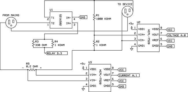
The block diagram is shown in Figure 1. Our device sits between the mains line and the device under test. Current measurements occur on the neutral line. The relay is switched on the AC live line. A voltage divider is used to step down the voltage to the correct levels. All signals are optically isolated before reaching the MCU.
Figure 1. System block diagram.
Hardware / Software Tradeoffs
Hardware was used to bring voltage levels into the appropriate range for the Mega32 internal ADC. In software, the Mega32 was used to sample the voltage levels at a frequency of 1 KHz and perform the appropriate calculations in real time. The software also handles interacting with the computer and controlling the relay switch.
The Mega32 ADC channels are multiplexed and not simultaneous. An external simultaneous ADC chip could have been used to sample current and voltage at the same time, resulting in slightly more accuracy. However, to save costs, the extra hardware was not used. The internal Mega32 ADC was switched in software to take one sample after the other. This was deemed good enough for our purposes.
Fixed point (20:12) was used instead of floating point to speed up multiplication and division operations. The Mega32 hardware performed floating point multiplication operations much slower than integer multiplication operations. Therefore, some accuracy was traded for speed.
Standards
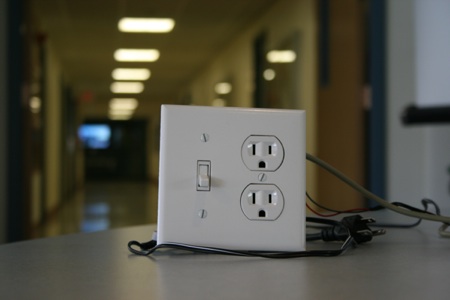
The sockets used in most American homes adhere to the NEMA 5-15 standard, set by the National Electrical Manufacturers Association. It is rated for 15 A / 125 V at 60 Hz.

Figure 2. NEMA 5-15 Socket. Source: Wikipedia.
Figure 1 shows the standard socket. The left wider flat blade is neutral, and the right flat blade is AC live. Neutral is the zero voltage reference point. The voltage on the live contact is measured with respect to the neutral contact. AC live oscillates between roughly +/- 170 V about that point. The circular hole is earth ground. It is used as a safety mechanism for device with metal casings, so that it does not produce a dangerous electric shock when people touch the case.
The standard IEC connector defined by International Electrotechnical Commission specification IEC 60320 is commonly used to connect mains AC power to devices such as computer. One of these was salvage for use in our project. The one we used was a 3-conductor standard rated at 16 A.
Patents, Copyrights, and Trademarks
There are quite a few commercially available professional AC power measurement devices on the market. Kill A Watt is a registered trademark. The name PowerBox does not knowingly infringe on any trademarks. The design of our project does not knowingly infringe on any patents.
Hardware Design
Voltage Measurement
To measure voltage, the general idea is to use a very large voltage divider to divide the 170 V peak-to-peak signal down to level which can be sampled by the ADC. Using a 1001:1 voltage divider (with 1 MΩ and 1 kΩ), as shown in the Appendix B schematic, 170 V peak-to-peak is divided down to 0.17 V peak-to-peak. A very large resistor (1 MΩ) was used in the divider to limit the current between AC live and neutral. Assuming a 170 V drop, only 0.17 mA flows through the 1 MΩ resistor, dissipating 0.03 W, well within the power ratings of the resistor. To calculate the line voltage from the voltage divider output, the following equation can be used:
![]() (Eq. 1)
(Eq. 1)
Current Measurement
To measure current, the general idea is to break the neutral line and insert a very small current-sensing resistor (0.2 Ω). This would create a small voltage difference across the resistor. Since we know the voltage drop and the resistor value, we can mathematically determine the current through the neutral line. Since the resistance is very small, very little power is dissipated through it. We carefully checked the ratings of this and other circuit components for power ratings. The resistor is rated for 3 W. We expected a 200 W computer to draw about 1.7 A. This results in a voltage drop of 0.34 V and a power dissipation of 0.58 W. To calculate the line current from the current-sensing resistor voltage drop, the following equation can be used:
![]() (Eq. 2)
(Eq. 2)
Isolation, Amplification, and Offset
In our first design iteration, we referenced the EnerJar design. We wanted to use an opamp bias the AC signal by 2.5 V in order to make the signal positive. The signal was to be put through a precision amplifier to convert it into the proper range for the ADC. This scheme would require that all of the grounds of each circuit element to be connected, which was deemed very dangerous. Therefore, after some analysis, it was rejected for safety reasons.
In our second design iteration, we added optoisolators to completely isolate the dangerous high voltage circuit from the MCU. Since the optoisolators stocked in lab were by nature digital devices, we wanted to use a PWM chip to convert the analog signal into pulses to send across the optoisolator. We also wanted to use precision amplifiers to convert the signal into the correct range. This would have been a workable solution, but we wanted to find a more efficient method that required fewer ICs.
In our third design iteration, a breakthrough occurred when we found the Avago Technologies HCPL-7520 linear optoisolator. This device has a linear transfer characteristics curve for input range -256 mV to 256 mV. The input is differential and the output is scaled to Vref. The gain is Vref / 0.512. This single chip allows us to bias the signal to Vref / 2, amplify it, and isolate it. It results in a solution that is simpler and cheaper to manufacture. The HCPL-7520 was used for both voltage and current measurements. Vref was set to Vcc (5 V) of the MCU. To calculate the input voltage of the HCPL-7520 from the output voltage, the following equation can be used:
 (Eq. 3)
Combining the voltage divider (Eq. 1) and current-sensing (Eq. 2) equations with (Eq. 3), we get:
 (Eq. 4)
 (Eq. 5)
The voltage output was connected to Port A.0 of the MCU. The current output was connected to Port A.1.
Power Switching
To do remote power switching, the Sharp S216S02 solid state relay was used. This relay is optically isolated and rated for 240 VAC and 16 A. We used this relay to switch the AC live line. A 330 Ω and a 1 kΩ resistor were placed in parallel (248 Ω series resistance) to limit the current of the light emitting diode in the relay. Port D.3 of the MCU was used as the output to control the relay.
Supply
On the high voltage side, the optoisolators were powered using a salvaged 12 V AC-DC unregulated power supply. We regulated it down to 5 V with a regulator. On the low voltage side, the optoisolators were powered using Vdd and Gnd of the MCU.
Physical Design
For physical design, a solder board was used to place our circuit. The left side of the board contained dangerous high voltage elements. The right side contained MCU inputs. The 2 sides were completely isolated. Cables from inside the IEC connector were used to connect AC lines. The IEC connector head was used to connect our device to the wall. Devices under test were connected via a wall socket. A salvaged serial cable was soldered to the port instead of an RS232 connector. Everything was contained inside a plastic wall box for safety. Please consult the Safety Section for how our device was isolated.
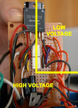
Figure 3. Circuit board.
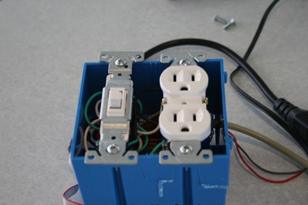
Figure 4. Open assembly.
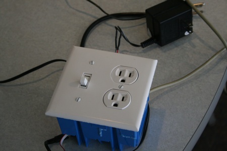
Figure 5. Closed assembly.
Software Design
Timer 0 prescalar was set to divide by 64. The TIM0_COMP interrupt was set to run every 250 ticks. The ISR updates 3 virtual timers for 3 different tasks. It is also responsible for updating the clock time, which is in the unix time format (seconds since January 1, 1970 UTC).
Task 1 runs every 1 sec. It simply blinks the LED on Port D.2 to verify that the MCU is running correctly. Task 2, which runs every 1 ms, is responsible for ADC input and all power calculations. It also handles data output to the serial port. Task 3, which also runs every 1 ms, is responsible for reading input and processing commands from the serial port.
ADC Sampling
To get accurate power calculations, we used Task 2 to get ADC samples at a frequency of 1 KHz. To sample 2 channels, a conversion on A.0 (voltage) was started by setting ADMUX.0 to 0 and ADCSR.6 to 1. A while loop was then used to wait for the conversion to finish. ADCH was then stored to a variable. A second conversion on A.1 (current) was immediately started by setting ADMUX.0 to 1 and ADCSR.6 to 1. This result from ADCH was also stored to another variable.
Aref of the ADC was set to Vcc, and the ADC was set to left adjust the result, giving us 8 bits of accuracy if we only read ADCH. Therefore, to get the input, the following calculation is done:
![]() (Eq. 6)
(Eq. 6)
Current and Voltage Calculations
To ensure that per-sample floating point math operations were done quickly enough, 20:12 fixed point was used, giving 0.00024 (1 / 4096) of decimal accuracy. The values from ADCH were immediately converted to fixed point.
To derive the actual line voltage and current values, (Eq. 4) and (Eq. 5) were combined with (Eq. 6) to yield:
 (Eq. 7)
 (Eq. 8)
Squared current and voltage values are summed up over 1000 samples. This summation is then divided by 1000 every second to get the RMS values. There are obviously some simplifications that can occur to optimize the number of operations, which will be detailed later. Note that Vref completely cancels out.
Power Calculations
To calculate real power, voltage and current are multiplied during every sample and summed up. After 1000 samples are taken, the power summation is divided by 1000 to get the average power over 1 second. The following equation describes the operation:
To calculate apparent power, Vrms and Irms should be multiplied together every second. However, this is optimized as shown in the next section.
Power factor was calculated by dividing average power from apparent power.
Optimizations and Fixed Point Overflow Workaround
To optimize per-sample calculations, only the voltages sampled by the MCU are stored, and not the actual current and voltage values. This was also required to prevent fixed point overflow. The conversion to actual values is done only once a second. We will attempt to illustrate the optimization.
After refactoring (Eq. 7) and (Eq. 8), we get the following:
![]()
![]()
Let us define the following:
![]()
![]()
Therefore, to get the RMS values, we then do the following:
The average power is then described as:
This way, the factors in front of the summation can only be multplied once per second to prevent fixed point overflow and optimize operations.
Frequency Calculation
To calculate frequency, the time of individual 0 voltage crossings are stored. The differences are calculated. These frequency samples were averaged over 1 second to reduce error.
Energy Calculation
To calculate energy used, the average power every second was converted into kilowatt-hours (divide by 3600) and summed.
Relay Control
If shutdown is set to 1, Port D.3 is turned off. If the calculated power is greater than the limit (threshold), the relay is also turned off by setting shutdown to 1. A user must manually turn the relay on again after the limit has been exceeded.
UART Communication
Serial input and output were done concurrently by using the USART_RXC and USART_DRE interrupts to ensure that it was non-blocking. UART functions from ECE 476 were incorporated. Task 2 uses the puts_init function to asynchronously output the data once every second. The format was as follows:
<unix time>:P<power>,S<apparent power>,I<current>,V<voltage>,F<frequency>,
	... E<energy>,R<power factor>
Task 3 used the gets_init function to asynchronously read UART input and use various string operations to process the following commands:
TIME <unix time (long)> - sets the clock time of the device
RELAY <0/1> - turns relay on or off
THRESHOLD <watts> - sets the wattage limit
C# Graphing and Control Application
A C# Windows application was written to communicate with the MCU. Please note that all calculations were done on the MCU. The C# application was used to display the power graph and report values. It was also used as a GUI to issue device commands. The ZedGraph open source library was used for graphing.
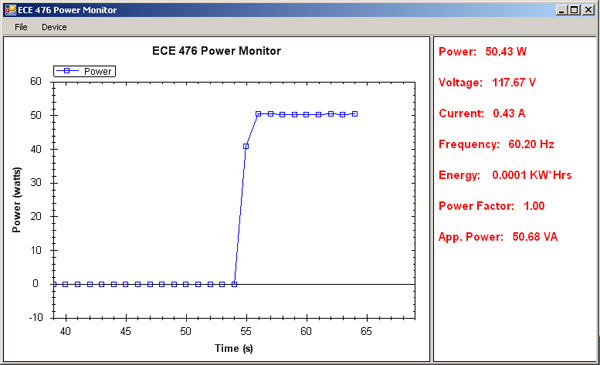
Figure 6. ECE 476 Power Monitor application.
Results
Our final device is set to sample at the rate of 1 KHz, and output data at the rate of 1 Hz. Since the microcontroller is handling all of the Analog-Digital conversion as well as all the calculation needed for the output, we decide not to push the MCU to its limit as we like some buffer incase a rare event happens in which the MCU takes longer to complete a specific task. Regardless, the waveform being sampled runs around 60 Hz, the sample rate of 1 KHz gives us about 16 samples per waveform, and it is likely that faster sampling can cause more noise within the collected data. And since our data is used to calculate the Root-Mean-Squared, any noise with high peak will be especially devastating to our result.
We designed this device to measure stable devices, so the 1 Hz report time is not terribly slow as there are very few devices that has power draw that changes faster than once a second. The designed application for this device is for power monitoring over duration of time, as it also keep track of total energy used through the plugs. Also the commercial power measuring device that we have also only updates at 1 Hz.
The error in measurement can be from opto-isolator noise as well as the lack of precision in ADC and data calculation. To test the accuracy of our project, we used a commercial power measuring device Watts Up? Pro to measure the statistics of power drawn by a single 50 W light bulb. The results are organized in Table 1.
Table 1: Accuracy Comparison for a 50 Watt Light Bulb
|
Our Project |
Commercial Product |
Error |
Total Power Draw (W) |
51.9 |
50.6 |
2.57% |
RMS Voltage (V) |
120.0 |
121.5 |
1.23% |
RMS Current (A) |
0.43 |
0.409 |
5.13% |
The absolute difference in the power measurement is about 1 W, which we consider is pretty good. We feel that with higher load or even a calibration our device can achieve better accuracy.
Safety in Design
Safety to the device is achieved through the use of optisolators as well as different power supplies. As one can see in Figure 3, the board can be divided up into two regions, the MCU safe region, and the unsafe region. Across the regions are the white linear optoisolator and the isolated AC relay. These components ensure that the any wiring mistakes or accidents in the unsafe region will not affect the safe region, which is connected to the MCU, which in turn in connected to computer via serial.
Safety to the operator is achieved by following the same strict guidelines in wiring of a house. The colors of the power lines are always used so that live line is always black, neutral line is white, and ground line is green. Wire twists are used to connect two power wires as one would do in wiring a house socket. In addition to these precautions, we always test our device before a live AC test so that we do not cause any damage to any other equipments or people. Further discussion will be presented in the ethical considerations section of Conclusions.
Other than the possible AC power short, our device should not interfere with anyone else’s design. Discussions of this prevention can be found in the safety section above as well as the ethical consideration section.
Usability
Our final version of the device is very user friendly. The operator only has to plug in all the necessary power supplies and plugs, and flip the switch to turn on the hardware portion of device. The software portion / data reporting can be activated by simply running a compiled executable file under Windows. The GUI is a standard Windows interface. When opening a connection to the device, a list of COM ports are automatically presented for the user to select. The power data is automatically graphed and results are shown on the right panel. This is much more usable than attempting to decipher and use the UART interface.
Conclusions
Our final version of the device mostly met our original design goals. We originally planned to be able to monitor and control the device remotely, either by Ethernet, wireless, or inferred protocol. We decided to forgo those ideas due to budget constraints. Instead we decided to finish a working version of the project on a timely basis and implement other features instead such as power factor and the power based auto shutoff. In general, we are happy about its accuracy and features. If we were to continue with this project, we would like to add features such as Ethernet so that many of these can be deployed in a home and hooked up to a central monitoring system.
IP Considerations
We were inspired by the commercial product Kill A Watt power measurement device in the top level feature design of the project. Further research reveals that Enerjar has a design for DIY power measurement device. Further examination shows however that their device does not utilize isolation or separate power supply and there for is not safe or as robust as we would like to be. In addition, the device does not interface with computer or utilize a relay for power control. However we did use their basic method of current and voltage detection, but because these are common knowledge, and almost the only way to accomplish, we do not feel that there is a patent issue that we are violating. All the codes in our project are written by ourselves or provided by the course, such as the mcu-serial interface commands.
Ethical Considerations
Throughout this project, the IEEE Code of Ethics is being closely followed. We know that our project, if improperly wired or used, can affect other groups as they work in the lab by triggering the circuit breaker and expose the groups to the risk of losing work and endure the mandatory 20 minutes of login time to the lab computer. So before any testing (plugging directly to the ac socket) we always thoroughly test our device to ensure that at least the ac wires are not incorrectly wired and that any risk of short would only damage our own device. Similarly, all live tests we conduct are done with the whole device fully packaged within the box, so that other people in labs or even ourselves would be exposed to any dangerous parts of the device, even so, we do seek the approval of our professor, Bruce Land, to double check that the circuit is good for live ac test and operation. We believe that these steps we have taken shows are acceptance of responsibility in making decisions consistent with the safety, health and welfare of the public.
Even with all these steps taken, we still clearly announce our intention to test our device and ask the others to save their work so the cost of any accident is minimized, this is in align with the IEEE Code of Ethics as we disclose the factors and conflict of interested to parties under the threat.
In the testing stages of the device, we did have a mechanism that assumed low current to be shut-off, but now in the final version, all measurements and calculations are done exactly as they would on paper and we did not need to calibrate or insert a “fudge factor” to obtain decent results. This shows that our device is honest and realistic in displaying the actual unadulterated measured data.
Through the making of the project, other peoples in the lab did offer suggestions, both as jokes or otherwise, to bring supernatural or malicious nature to our device, or even name our project “The Doomsday Device.” It is difficult to say that these requests resemble bribes as they are not made with much incentive for our own benefit. Regardless, these requests seemed very difficult if not impossible to accomplish and they do conflict with the engineering ethics, and are promptly rejected, as the code of ethics clearly states “4. To reject bribery in all its forms”.
Devices like ours already existed, and some even commercially available. We improve the understanding on this technology by introducing interface to computer that is easy to use, graphing the data in real time, as well as minimizing the cost for such product. In other products designs safety was not fully address as ours, and we feel we have made a major improve on that.
Although there were two of us in the group, the hardware part was mostly done by one of us. We feel this is in line with the code of ethics as the other group member, even as he struggles to restraint himself from doing any of the soldering or wiring work, understands that he lacks to proper experience in the field and chooses not to undertake these tasks.
We have demoed projects, although not the final version, to the professors and lab ta’s in the course. They have offered valuable criticisms and suggestions to our design, such as the safety concerns that Professor Land brought up. We verily accepted these safety suggestions and integrated them to our design. During our times in the lab, we have also offered suggestions to other groups as they toil on in their work. We believe this shows that we have sought, accepted, and offered honest criticism of technical work, and acknowledged and corrected errors, and credited properly the contributions of others.
All members of our group are the race, religion, gender, disability, and age. We didn’t have a problem getting along with each other and with the other people involved in the class.
As stated above, we have take steps to avoid injury to others physically by our device, and as this writing about the code of ethics does not contain names, reputation and employment are not tarnished or harmed, which is expected of us according to the code of ethics.
In the lab, we tried to help the other groups in the project whenever we could. In addition to the technical assistance, we also provided mental, spiritual, moral, ethical, and motivational support to our fellow colleagues and co-workers. Although we cannot say with certainty, but these supports may have helpful in their professional development and their following of this code of ethics.
Legal Considerations
Our device does not produce any more interference than a standard power socket / power strip and MCU. Therefore, there is no reason to believe that it would not meet FCC Class A digital device requirements.
Appendix A: Program Listing
1: /*
2: * final.c
3: *
4: *
5: * Created by Cliff Jao and Xi Guo on 4/14/08.
6: *
7: * Voltage on A0
8: * Current on A1
9: *
10: * Serial commands:
11: * TIME <long seconds>
12: * RELAY <0/1>
13: * THRESHOLD <watts>
14: */
15:
16: #include <Mega32.h>
17: #include <stdio.h>
18: #include <math.h>
19: #include <string.h>
20:
21: #define SAMPLES 1000
22: #define t1 1000 // 1000 ms.
23: #define t2 1 // 1 ms
24: #define t3 1 // 1 ms
25: #define R_SENSE 0.2
26: #define Vref 5.0
27:
28: char *cmds[] = {"TIME", "RELAY", "THRESHOLD"};
29: #define TIME 0
30: #define RELAY 1
31: #define THRESHOLD 2
32:
33: long FP_ADC_CONV, FP_OFFSET;
34:
35: ////// 20:12 fixed point macros
36: #define int2fix(a) (((long)(a))<<12) //Convert char to fix. a is a char
37: #define float2fix(a) ((long)((a)*4096.0)) //Convert float to fix. a is a float
38: #define fix2float(a) ((float)(a)/4096.0) //Convert fix to float. a is an int
39: #define multfix(a,b) ((long)((((long)(a))*((long)(b)))>>12))
40:
41: long fpVSquareSum;
42: long fpISquareSum;
43: long fpPowerSum;
44: float rPower, aPower;
45: float powerFactor;
46:
47: float iScaleFactor, vScaleFactor, rpScaleFactor;
48:
49: ///// Periods //////
50: long fpVLastValue;
51: unsigned long vPeriodSum;
52: int vLastZeroMsec;
53: unsigned int vPeriodCount;
54:
55:
56: ///// Watt Hour Stuff ////
57: float kWattHrs;
58:
59: unsigned char r_index, r_buffer[40], r_ready, r_char;
60: unsigned char t_index, t_buffer[350], t_ready, t_char;
61: void gets_init();
62: void puts_init();
63:
64: char time0, time1, time2, time3;
65: unsigned int sample;
66:
67: // seconds since January 1, 1970 (UNIX time)
68: unsigned long unixtime;
69: unsigned int msecs;
70: unsigned long offTime;
71: unsigned long onTime;
72:
73: long threshold; // power limit
74: char shutdown; // whether to shut down the relay
75:
76: void task1();
77: void task2();
78: void task3();
79: void initialize();
80:
81: void main() {
82: initialize();
83:
84: // launch tasks if necessary
85: while(1) {
86: if (time1 == 0) task1();
87: if (time2 == 0) task2();
88: if (time3 == 0) task3();
89: }
90: }
91:
92: void task3() {
93:
94: int int_param, i;
95: char cmd;
96: char cmdStr[50];
97: char param[50];
98: char *space;
99: int spaceIndex;
100:
101: time3 = t3;
102:
103: // return if not ready yet
104: if (r_ready != 1) return;
105:
106: // try to find space
107: space = strchr(r_buffer, ' ');
108:
109: if (space != NULL) {
110: // space was found, extract param
111: spaceIndex = space - r_buffer;
112: strncpy(cmdStr, r_buffer, spaceIndex);
113: cmdStr[spaceIndex] = '\0';
114: strcpy(param, space + 1);
115: }
116: else
117: {
118: // space not found, just copy over
119: strcpy(cmdStr, r_buffer);
120: }
121:
122: // cmd will be -1 if no command
123: cmd = -1;
124: for (i = 0; i < 3; i++) {
125: if (!strcmp(cmdStr, cmds[i]))
126: {
127: cmd = i;
128: break;
129: }
130: }
131:
132: switch(cmd) {
133: case TIME:
134: sscanf(param, "%ld", &unixtime);
135: msecs = 0;
136: break;
137: case RELAY:
138: sscanf(param, "%d", &int_param);
139: if (int_param) shutdown = 0;
140: else shutdown = 1;
141: break;
142: case THRESHOLD:
143: sscanf(param, "%ld", &threshold);
144: break;
145: }
146:
147: //printf("CMD OK\n\r");
148: gets_init();
149: }
150:
151: void task1() {
152: time1 = t1;
153: PORTD.2 = ~PORTD.2;
154: }
155:
156: void task2() {
157: char Ain0, Ain1;
158: long fpVin0, fpVin1, fpVin, fpIin;
159: long fpAin0, fpAin1;
160: float vAvg, iAvg;
161: int vPeriod;
162:
163: time2 = t2;
164:
165: // start conversion for channel 0
166: ADMUX.0 = 0;
167: ADCSR.6 = 1;
168:
169: // wait for conversion to finish
170: while (ADCSR.6);
171:
172: // read Ain0
173: Ain0 = ADCH;
174:
175: // start conversion for channel 1
176: ADMUX.0 = 1;
177: ADCSR.6 = 1;
178:
179: // wait for conversion to finish
180: while (ADCSR.6);
181:
182: // read Ain1
183: Ain1 = ADCH;
184:
185: // go to 20:12 fixed point
186: fpAin0 = (long)Ain0 << 12;
187: fpAin1 = (long)Ain1 << 12;
188:
189: // calculate Vin of the ADC
190: fpVin0 = multfix(fpAin0, FP_ADC_CONV) - FP_OFFSET;
191: fpVin1 = multfix(fpAin1, FP_ADC_CONV) - FP_OFFSET;
192:
193: // sum up power or squares
194: fpPowerSum += multfix(fpVin0, fpVin1);
195: fpVSquareSum += multfix(fpVin0, fpVin0);
196: fpISquareSum += multfix(fpVin1, fpVin1);
197:
198: ///////// FREQUENCY CALCULATION //////
199: if (fpVLastValue < 0 && fpVin0 >= 0) {
200: // found a zero crossing from neg. to pos.!
201: vPeriod = msecs - vLastZeroMsec;
202:
203: // make sure it's not an edge
204: if (vPeriod > 0) {
205: vPeriodSum += vPeriod;
206: vPeriodCount++;
207: }
208:
209: vLastZeroMsec = msecs;
210:
211: }
212:
213: fpVLastValue = fpVin0;
214: ///////////////////////////////////
215:
216: sample++;
217:
218: if (sample == SAMPLES) {
219: // this only happens once a second,
220: // so floating point mults should be okay
221: vAvg = (float) sqrt(vScaleFactor * fpVSquareSum);
222: iAvg = (float) sqrt(iScaleFactor * fpISquareSum);
223: rPower = (float) rpScaleFactor * fpPowerSum; // watts
224: aPower = vAvg * iAvg; // VA
225: powerFactor = rPower / aPower;
226: kWattHrs += rPower / 3600000.0;
227:
228: sprintf(t_buffer, "%ld:P%3.2f,S%3.2f,I%3.2f,V%3.2f,F%3.2f,E%f,R%3.2f\n\r",
229: unixtime, rPower, aPower, iAvg, vAvg, 1000.0 * (float)vPeriodCount
230: / (float)vPeriodSum, kWattHrs, powerFactor);
231: puts_init();
232:
233: if (rPower > threshold) shutdown = 1;
234:
235: if (shutdown) PORTD.3 = 0; // turn relay off
236: else PORTD.3 = 1;
237:
238: // reset for next sample
239: fpVSquareSum = 0;
240: fpISquareSum = 0;
241: fpPowerSum = 0;
242: vPeriodSum = 0;
243: vPeriodCount = 0;
244: sample = 0;
245: }
246: }
247:
248: // compare match interrupt
249: interrupt [TIM0_COMP] void timer0_compare(void) {
250: if (time1 > 0) --time1;
251: if (time2 > 0) --time2;
252: if (time3 > 0) --time3;
253:
254: // update wall clock
255: msecs++;
256: if (msecs == 1000)
257: {
258: msecs = 0;
259: unixtime++;
260: }
261: }
262:
263: void initialize() {
264: long t;
265:
266: /////////////// TIMER 0 ///////////////////////
267: TIMSK = 2; // turn on timer 0 compare match ISR
268: OCR0 = 250; // sets compare to 250 ticks
269: TCCR0 = 0b00001011; // sets prescalar to 64
270:
271: //set up UART
272: UCSRB = 0x18;
273: UBRRL = 103;
274:
275: unixtime = 0;
276: msecs = 0;
277:
278: DDRD = 0xFF; // output
279: PORTD.2 = 0;
280: PORTD.3 = 1; // turn relay on
281:
282: threshold = 1000;
283: shutdown = 0;
284:
285: kWattHrs = 0;
286: time1 = t1;
287: time2 = t2;
288:
289: vScaleFactor = 1002001.0 / (4096.0 * SAMPLES);
290: iScaleFactor = 1 / (R_SENSE * R_SENSE) / (4096.0 * SAMPLES);
291: rpScaleFactor = 1001.0 / R_SENSE / (4096.0 * SAMPLES);
292:
293: // internal Aref = Vcc, left adjust result
294: ADMUX = 0b01100000;
295: //enable ADC and set prescaler to 1/128*16MHz=125,000
296: //and clear interupt enable
297: ADCSR = 0b11000111;
298:
299: // calculate conversion factor
300: //FP_ADC_CONV = float2fix(Vref / 256.0);
301: FP_ADC_CONV = float2fix(0.512 / 256.0); // opto
302: //FP_I_CONV = float2fix(1 / R_SENSE);
303:
304: FP_OFFSET = float2fix(0.256);
305: #asm("sei")
306:
307: gets_init();
308: }
309:
310: //**********************************************************
311: //UART character-ready ISR
312: interrupt [USART_RXC] void uart_rec() {
313: r_char=UDR; //get a char
314: //build the input string
315: if (r_char != '\r') r_buffer[r_index++]=r_char;
316: else {
317: putchar('\n'); //use putchar to avoid overwrite
318: r_buffer[r_index]=0x00; //zero terminate
319: r_ready=1; //signal cmd processor
320: UCSRB.7=0; //stop rec ISR
321: }
322: }
323:
324: /**********************************************************/
325: //UART xmit-empty ISR
326: interrupt [USART_DRE] void uart_send() {
327: t_char = t_buffer[++t_index];
328: if (t_char == 0) {
329: UCSRB.5=0; //kill isr
330: t_ready=1; //transmit done
331: }
332: else UDR = t_char ; //send the char
333: }
334:
335: //**********************************************************
336: // -- non-blocking keyboard check initializes ISR-driven
337: // receive. This routine merely sets up the ISR, which then
338: //does all the work of getting a command.
339: void gets_init() {
340: r_ready=0;
341: r_index=0;
342: UCSRB.7=1;
343: }
344:
345: //**********************************************************
346: // -- nonblocking print: initializes ISR-driven
347: // transmit. This routine merely sets up the ISR, then
348: //send one character, The ISR does all the work.
349: void puts_init() {
350: t_ready=0;
351: t_index=0;
352: if (t_buffer[0]>0) {
353: putchar(t_buffer[0]);
354: UCSRB.5=1;
355: }
356: }
Appendix B: Schematics
Appendix C: Budget
Item |
Unit Price |
Quantity |
Price |
| Ohmite 13FR200E current sense resistor | $1.72 |
1 |
$1.72 |
| Avago Technologies HCPL-7520 linear optoisolator | $3.83 |
2 |
$7.66 |
| Sharp S216S02 solid state relay | $5.83 |
1 |
$5.83 |
| Atmel Mega32 | $8.00 |
1 |
$8.00 |
| Custom PC board | $5.00 |
1 |
$5.00 |
| Power supply | $5.00 |
1 |
$5.00 |
| Power supply | Salvaged |
1 |
Salvaged |
| Solder board | $2.50 |
1 |
$2.50 |
| RS232 serial cable | Salvaged |
1 |
Salvaged |
| Max233CPP | Sampled |
1 |
Sampled |
| IEC power connector | Salvaged |
1 |
Salvaged |
| NEMA 5-15 power socket, switch, and wall box | $9.99 |
1 |
$9.99 |
| Total: | $45.70 |
||
Appendix D: Member Tasks
Cliff Jao
- Circuit design
- Circuit experimentation
- Software coding (MCU and C#)
- Testing and debugging
- Report
- Webpage creation
Xi Guo
- Circuit design
- Circuit experimentation
- Soldering and assembly
- Testing and debugging
- Report
References
- Hambley, Allan R. Electrical Engineering: Principles and Applications. Third Edition. Prentice Hall, 2005.
- Datasheet: Avago Technologies HCPL-7520 linear optoisolator
- Datasheet: Sharp S216S02 solid state relay
- Datasheet: Ohmite 13FR200E current sense resistor
- EnerJar Website
- ECE 476 Website
- Wikipedia Article: AC power
- Wikipedia Article: Domestic AC power plugs and sockets
- NEMA - National Electrical Manufacturers Association Website
- Vendor: DigiKey