Teaching an old clock new tricks
David Hattaway (Email)
Ho-Jun Suk (Email)
While exuding retro style, the alarm clock in its original state lacked many desirable features of today's alarm clocks. The only controls consisted of a single on/off switch. It also lacked AM/PM indication, making it impossible to sleep for more than 12 hours.
Our project sought to maintain the integrity of the original alarm clock, while using a microcontroller to automatically manipulate the controls, in order to implement features like snooze, alarm reset, and daily alarms.
High Level Design
Motivation
The clock was purchased several years prior from Goodwill. Initially, the retro styling, and the annoyingly effective nature of the buzzer mechanism made it a favorite. However, the shortcomings quickly came to light under a typical highly variable college sleep schedule. Every night required preparation by manually turning the unidirectional alarm wheel and resetting the alarm to the on position. Once the alarm started to sound, there was no snooze mechanism or alarm reset to stop the alarm. Additionally, when it was time to make up for lost sleep, the nature of the clock mechanism allowed for a maximum of 12 hours of sleep. Eventually, the alarm functions of a cell phone replaced it as the preferred alarm clock.
Today, we are seeing a resurgence of retro style. In fact, "flip style" alarm clocks can be purchased new from various retailers. However, by reusing the old clock we can promote recycling, maintain the high build quality, and also make for a great project. At the same time, we were able to incorporate daily alarm features normally found only on more high end modern alarm clocks.
Logical Structure
- Time Signal
- A circuit was constructed to convert the 60Hz 120VAC utility power into a 60Hz 5V digital signal, which we used to keep microcontroller time synchronized with that of the alarm clock
- PM Indication
- We mounted an LED to the front of the alarm clock to given a quick and easy indication of PM time
- Alarm Wheel Control
- The alarm works on a wheel type mechanism that activates the buzzer based on its position. This alarm wheel in the original clock is adjusted manually, but we added a stepper motor that gave us the ability to manipulate the alarm with MCU software
- Deactivating Alarms
- We maintained the full alarm mechanism of the original clock, which meant that an undesired alarm could potentially sound while manipulating the alarm wheel, as well as during the opposite AM/PM half of the day. To rectify this we added a solenoid which is able to temporarily deactivate the internal alarm mechanism
- User Controls
- The original controls consisted of only alarm and time setting gears, and a single on/off switch. In order to implement the desired functionality we added a total of 7 buttons for various functions
- User Interface
- We mounted a small LCD to the rear of the clock to enable to user to set and query alarms and settings
Tradeoffs
Certain desirable features have been left out of this project. For instance, we had the idea of automatically adjusting the alarm clock time to adjust for daylight savings, etc. However, this would have required more extensive hardware which would have made it impossible to fit everything in the limited internal space of the original clock.
The user is required to perform an initial calibration of the time and alarm time shown on the clock. Ideally the user would not have to perform this step, however this would have required more complex sensors to detect the position of the clock gears. This was not feasible due to the small spacing of the gears, as well as our budget constraints. However, this is not a major concern as the calibration is only required when resetting the time, which is performed rarely (power loss, daylight savings time). Additionally, all settings are stored in EEPROM, so that no reset will be required in the case of a short power flicker.
Standards
- NAESB WEQ Manual Time Error Correction Standards (WEQBPS 004)
- This standard applies because we are depending on the utility frequency to maintain synchronization with the clock. Typical electro-mechanical clocks such as this one depend on the stability of this 60Hz frequency to keep accurate time. However it is impossible to maintain 100% accuracy at all times with the varying load electric utilities must support. The utility must keep track of the official NIST time and adjust the frequency to account for any discrepancies. Today's power grid is interconnected and to exchange power between grids it is vital that they stay synchronized. This standard governs the methods for making time error corrections to the frequency, including taking into account leap seconds.
- Because of our dependence upon the 60Hz frequency standard, this clock would not keep accurate time in other countries which operate at a different frequency. We did not introduce this limitation as it existed in the original alarm clock design, and our code is written such that it can be easily modified to operate with a different frequency clock if desired
Patents and Trademarks
While no definitive sources were found, we believe this alarm clock was designed prior to 1988, which would make any patents beyond the 20 years term on US patents.
Additionally, we are merely designing an add-on mechanism for the existing alarm clock design, which would certainly fit within fair use guidelines.
GE® and The GE Monogram, are trademarks of General Electric Company.
The GE trademark is only used to denote the existing retro alarm clock. Our modifications beyond the original design should not be attributed to General Electric Company.
Software Design
Time Values
Time and alarm values are stored as a struct in EEPROM. By storing in EEPROM, the values will not need to be reset for a momentary power blip. The struct holds values for day, hour, minute, second, and tick. There are 60 ticks in 1 second
Stepper Motor
The motor is controlled by energizing each of 4 coils in turn. However, we wanted greater accuracy, so we used half stepping. This requires alternately energizing 2 coils and then 1 coil in sequence. We use the lower 4 bits of a char to represent each of the steps, and keep the sequence in order in the array.
We keep track of the number of steps remaining to turn in a global variable steps_remain. A task runs every 25 ms, check to see if this variable is positive, and if so turns another step, by incrementing through the steps array and outputting it to the PORT, then decrementing steps_remain.
When we wish to decrement the alarm wheel, we implemented a function start_step, which takes in an integer number of minutes to decrement the alarm wheel. This number is converted into a number of steps, based on a measured number of steps per wheel revolution, and the 12*60 minutes per revolution. We then set steps_remain, to begin the motor turning. We then take the number of steps and convert it back into the actual amount of time which is being subtracted, accurate to within 1 tick. This number is then subtracted from the calibrated alarm wheel time, so that we maintain an accurate record of it's position.
Solenoid
We use the solenoid to deactivate the hardware alarm when it is not wanted. We attempted to just leave the solenoid on for the period of time when the clock would pass over unwanted alarm intervals, however it would get too hot. So instead we used the stepper motors to turn the wheel to avoid these alarms. Thus, the only time when the solenoid was required is during the actual stepping operation. We exploited this to make operation much simpler. The stepper motors only needs 4 wires, however at each step the motor controller simply outputs the entire char to the port, so we set the 5th bit of all the step chars to high, and connected the stepper motor on the 5th port pin. The solenoid is turned off in the same manner as the motor, so that was all the control necessary.
PM Indicator
The PM Indicator is a simple LED, so we have a task which and checks to see what the current time is. If the hour of the time is >= 12, then we set the pin high, turning on the LED, otherwise we assert it low, turning off the LED.
Alarm Polling
We have a task which regularly checks to see if there are any alarms coming up, and if so correctly positions the alarm wheel.
The first step is to take the current day and look up the corresponding alarm. We check the alarm hour to make sure that it is valid (less than 24). We then convert the current time and alarm to minutes, and calculate the difference between them. If the difference is within a certain margin (30 minutes). If it is, we then calculate the difference in minutes between the time shown on the alarm wheel and the requested alarm time, and call start_step to correctly position the wheel.
However, if we are not positioning the wheel for a requested alarm, then we have to ensure that the wheel is not in a position to sound an alarm inadvertently. To do this we calculate the wheel time and current time in minutes, and calculate the difference between them. If the difference is too close, then we add 90 minutes to this delta value and step the wheel by this amount, so that the wheel will be positioned before the current time, and avoid buzzing.
Button Input
We had poll input from 7 buttons: Snooze, Alarm Reset, Mode Change, Hour Increment and Decrement, and Minute Increment and Decrement. All buttons were connected to PIND, leaving PIND.2 open for the external interrupt. We implemented debouncing using a state machine checking the status of this button input char (ignoring the external interrupt pin). The state machine was set to track how long a button remained in the pushed state, and for the increment and decrement buttons, perform actions every second. When not held down, or with any other button, the action is called as soon as the button is released.
Snooze
The snooze button should be pressed when the alarm is currently buzzing and you want to sleep. The amount of time is defined as SNOOZE_MIN, which is our project was set to 15 minutes. So, when snooze is pressed it initiates the stepper to increment the alarm wheel time by 15 minutes, which corresponds to decrementing it by (12*360 - 15) minutes, because the wheel is uni-directional. it also sets a timer so that the alarm polling function knows not further adjust the alarm wheel time.
Alarm Reset
Alarm reset is used to turn off a currently sounding alarm. This is implemented by turning the alarm wheel until the alarm time is prior to the current time, so it simply initiates the stepper to decrement the alarm wheel time by enough to deactivate the buzzer. It also sets the same snooze timer so that the alarm does not reset itself.
Mode Change
The program keeps a global "mode" variable which keeps track of the current user interface mode of the alarm clock. There are 9 modes, corresponding the time calibration, alarm calibration, and setting alarms for the 7 days of the week. Time calibration mode is used to synchronize the software clock with the time that is displayed on the original clock. Similarly alarm calibration mode synchronizes the time shown on the alarm wheel. Whenever the mode change is released, the software cycles through the modes, as evidenced by a change in what the LCD displays.
Hour Increment and Decrement
The operation of these buttons depend on what mode the alarm clock is in. In all of them, they will change the hour of the corresponding alarm, or calibration value. In time calibration mode, it is necessary to also calibrate the current day, so when you increment past 23, it will cycle to the next day, or below 0 to the previous. The alarm wheel only shows 12 hours, so it will roll over past 11 (hours 0:11). For the normal alarm modes, we wanted the capability to disable alarms on particular days, so incrementing past 23 will set the alarm to disabled, incrementing again will roll over to 0, and likewise decrementing past 0.
Minute Increment and Decrement
These are simpler than the hour buttons and simply change the minute of the current mode, rolling over between 59 and 0.
LCD Display
The top line of the LCD simply displays the current mode: "Calibrate Time", "Calibrate Alarm", "Sunday Alarm", ...
The second line displays the time value of the mode in 24 hour format (12 for alarm calibration): (hh:mm)
In time calibration it will display the day before the time, and in the 7 alarm modes, if the alarm is disabled the time will not be displayed an instead "DISABLED" will be shown.
Hardware Design
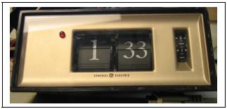
Original Clock
The alarm clock used for this project is a “flip clock.” Unlike digital clocks, it keeps track of time in analog, with an electrical motor that continuously spins two wheels, one of which is connected to the minute display and another to the hour display.
The alarm is controlled by alarm bar, wheel, and switch that are shown in the picture below:
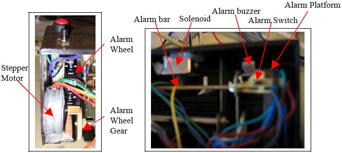
Original Alarm Control Mechanism (Note: Stepper motor and solenoid were not part of the original alarm clock. They were added to the clock for MCU-based alarm control as described in following sections)
The clock sounds the alarm only when the alarm buzzer makes contact with the alarm platform. Once the contact is made, the alarm buzzer vibrates and collides with the platform at a very high frequency, producing a beating sound.
There is a small hole in the alarm wheel that the alarm bar can move into. Once the clock time matches the alarm time, the position of the hole matches that of the alarm bar, and the bar moves in towards the alarm wheel. As the bar moves into the hole, the alarm buzzer makes contact with the alarm platform and sounds the alarm. Once the clock time is about 25 minutes after the alarm time, the alarm bar comes out of the hole and moves back to its original position. As the bar moves away from the alarm wheel, it pushes the alarm buzzer up, breaking the contact between the buzzer and the alarm platform. Once the contact between the buzzer and the platform is lost, the alarm is stopped.
When the alarm switch is moved to the “OFF” position (towards the alarm wheel), the edge of the switch pushes the buzzer up and breaks its contact with the platform. As a result, even when the clock time matches the alarm time, the alarm buzzer cannot make contact with the platform, and the clock does not sound the alarm. When the switch is moved to the “ON” position (away from the alarm wheel), the switch moves the buzzer down, and it can make contact with the platform when the alarm bar is moved towards the alarm wheel.
Clocking the MCU
To establish an accurate time base for the MCU, we used the circuit below to extract 60Hz, 5V square-wave from the 9VAC wall transformer that we found in the lab:
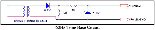
60Hz Time Base Circuit
The 0.7V diode allows the current to flow from the transformer to the resistors, but it blocks the current in the opposite direction. As a result, only positive voltages of the 60Hz, 9VAC sinewave signal appear at the diode output, producing 60Hz, 9VAC half-wave signal. 10kohm resistor provides a DC current path, so that the AC voltage output from the transformer does not increase much higher than 9VAC. 1kohm resistor limits the amount of current flowing to the zener diode and protects the zener diode from burning out due to high current. The 5.1V zener diode clips any voltage higher than 5.1V, so it transforms 60Hz, 9VAC half-wave signal into a 60Hz, 5V square-wave signal with 50% duty cycle. This 5V square-wave signal is an ideal source for producing an accurate time base, because its rising and falling edges happen at a precise period without much delay, and it oscillates from 0 to 5V, which are TTL values that can be fed into the MCU. To invoke external interrupts that occur 60 times per second, this 5V square-wave was fed into the external interrupt pin, PortD.2. Please refer to Software Design section for a detailed description on the software setup for 60Hz and 1 second time bases.
Above circuit was soldered onto the solder board and attached to the interior of the clock casing. As shown in the picture below, a small hole was drilled on the clock casing to allow the transformer output to connect to the circuit via the power plug:
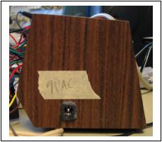
9VAC Plug on the Clock
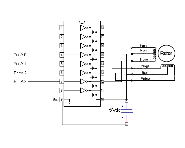
Stepper Motor
To control the alarm wheel, we used a unipolar stepper motor, Pf35T-48L4. The motor was glued into the clock casing with its gear touching the alarm wheel as shown in the picture in Original Clock section.
The unipolar motor has two three-pin connectors, each with one common and two coils. By following the procedures outlined in Other Stepper Motors, we were able to determine the stepper motor windings as shown in the figure below:
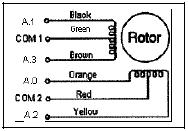
Stepper Motor Windings
For full-stepping, commons are kept at Vcc while the coils are connected to Vcc one at a time (full step animation). For our motor, the coil connected to the orange lead is connected to Vcc, followed by brown, yellow, and black wires to step in clockwise direction. For half-stepping, commons are again kept at Vcc, but coils are connected to Vcc in a different pattern. One coil is initially connected to Vcc. While keeping the coil connected to Vcc, an adjacent coil is connected to Vcc, exciting two coils at once. The first coil that was connected to Vcc is then disconnected, while keeping the second coil’s connection to Vcc. The third coil is then connected to Vcc, and the same pattern repeats (half step animation).
MCU is useful in generating the stepping sequence for the motor, but the output current from its port pins are too small to drive the motor with enough torque. Inductive spikes that happen during motor stepping can also destroy the port pins that are directly connected to the motor. As shown in the schematic below, we decided to use high-voltage, high-current Darlington arrays in ULN2803 to protect the MCU while driving the motor with large torque:
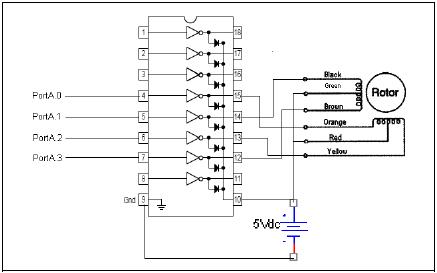
Stepper Motor Control Circuit
As shown in the figure above, a 5V, 1A external power source available in ECE 476 lab was used to drive the motor circuit.
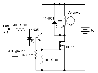
Solenoid
To control the alarm bar that was described in the Original Clock section, we used a miniature 5VDC solenoid, SOL-129. The solenoid was glued into the clock casing with its plunger mechanically connected to the alarm bar by a wire as shown below:
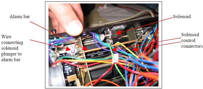
Solenoid and Alarm Bar in the Clock
Since the solenoid pulls its plunger when it is powered through two control connectors, the wire that ties the plunger with the alarm bar pulls the alarm bar and disables the alarm whenever the solenoid is powered on. To return the plunger and the alarm bar to their powered-down positions, we used a rubber band hooked onto the plunger and the clock casing, so that the alarm is re-enabled when the solenoid is not powered on.
Solenoids can be easily controlled by the MCU, but the output current from MCU port pins are too small to drive the solenoid with enough pulling power. To use the MCU to control the solenoid with enough current, we used the motor control circuit that was used in Lab 5:
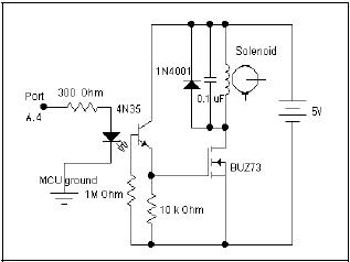
Solenoid Control Circuit
As shown in the figure above, the same 5V, 1A power source that drives the stepper motor was also used to drive the solenoid circuit.
Buttons
We had 6 normally open buttons (MPB-1B) for 6 different functions; mode change, reset alarm, increment alarm hour, decrement alarm hour, increment alarm minute, and decrement alarm minute. We also had a bigger button (PB-138) for triggering the snooze function. One lead of each button was connected to a Port D pin, and another lead was connected to the MCU ground to make the buttons active low. When the button is pressed, it shorts the MCU ground to the port pin, which consequently reads a logic low. As described in Software Design section, the pull-up resistors in the port pins were enabled to prevent the port pins from floating and to ensure stable detection of button presses.
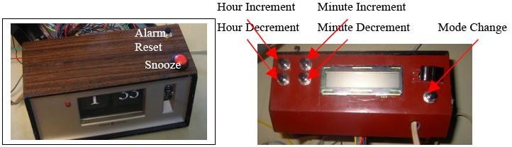
Buttons Mounted on the Clock
As shown in the picture above, the buttons were placed on the clock by first drilling a hole for each button and screwing it into the clock casing.
LCD
We used a 16- character by 2-line LCD, LCD-117, to display calibrated current time and day, calibrated alarm wheel time, and daily alarms. This LCD was very similar to the LCD that we have used for our previous labs, so we connected 14 pins of the LCD to GND, VCC, and PortC pins as described in the ECE476 Lab 1 Procedure. We found that the LCD had good contrast when the ajdustment pin 3 was connected to ground.
LED
For AM/PM indication, we used a red LED that we found in ECE 476 lab. One lead of the LED was connected to PortB.7, while another lead was connected to the MCU ground, so that the MCU can easily turn the LED on after 12:00 noon and off when it is past 12:00 midnight. The LED was placed on the front side of the clock as shown in the picture below:
AM/PM LED
Results
Accuracy
Since we used the same 60Hz time signal, the software time should remain synchronized with the clock time to within the accuracy of the original clock motor. We do not have an effective way to measure this, however no gross inaccuracies were observed during testing, and in typical use the time will need to be reset at least twice per year for daylight savings time, at which time any inaccuracies will be reset.
The largest source of inaccuracy was that we must depend on the user to input the precise time and alarm position of the clock. This is difficult given that the smallest granularity of display is 1 minute, and the alarm wheel is marked at 15 minute increments. However, we accounted for this source of inaccuracy by allowing for a certain margin of error. For instance, the alarm wheel is advanced several minutes prior to the scheduled alarm time, so that the alarm will be in the proper position at the right time, even if the software and hardware clocks differ by a minute or two. The only major effect is that there may be synchronization issues between the PM indicator, and when the 11:59-12:00 transition occurs on the hardware clock. The PM LED is controlled completely by software, whose clock is completely independent of the hardware clock. We had an idea of implementing a simple sensor to detect this 11:59-12:00 transition, but the space proved to be too small to implement such a detector.
The other source of inaccuracy was simply due to the granularity of the stepper, which makes it impossible to set an alarm time down to the precise minutes. However, we have structured our code such that we have precise knowledge of the wheel position at all times, so that differences in actual and requested position do not propagate through the clock operation. This inaccuracy was present in the original design of the alarm clock, as the granularity of the gears on the alarm wheel was also more than 1 minute.
Safety
The primary safety concern was that the clock sources power from the 120 VAC line without using an external transformer. We maintained safety by keeping the clock closed so that any parts of the clock that carry current is completely sealed in. With such an old appliance, care had to be taken to ensure the electrical cord does not expose any wires.
The only other safety concerns were those that apply to any other electrical appliance (keep away from water, small children, etc).
Furthermore, the alarm clock must not be thrown in frustration, as you may damage the casing and expose yourself to dangerous utility electricity.
Interference
During testing, we did not observe any interference with other final projects or other equipments. The only possible interference was that our alarm buzzer may have startled other groups or interfered with their concentration. However, the loud alarm that effectively interferes sleep is the goal of the buzzer and such performance is desirable. Noise was kept to a minimum while in the lab.
Some noise was observed in the time base signal, however we implemented software controls, such that we ignore any ticks outside of the error range of the MCU crystal. This control was seen to be effective in testing.
Usability
We found the modified alarm clock to be highly usable. We implemented many features such as hour increment/decrement and minute increment/decrement buttons that can be used to change time, alarm wheel time, and daily alarm time. When the buttons were held down, hour or minute was continuously modified in the appropriate direction to make the faster interface. The automatic daily alarms, alarm reset, and snooze functions made the alarm clock much more usable for someone who is lazy or has a variable sleep schedule.
Color blind individuals will be happy to find that all controls and indicators are based on spatial orientation and do not require the user to distinguish between colors beyond reading the characters on the clock and LCD.
We did not design our modification for the blind or deaf, as the original clock would have been unusable by either community, and we intended our project to be a direct extension of the existing functionality, rather than adding new accessible interface or waking mechanisms. It could however be used only as a clock by the deaf, or if preset by a sighted assistant, the alarm clock would still function for waking the blind. The only controls necessary to use the clock in this manner are the snooze and alarm reset buttons, both of which are placed distinctly on the top of the clock, with the snooze button having a distinctly different feel than the other buttons.
Speed of Execution
Execution speed was not a primary concern for our project. The clock displayed time with a maximum granularity of 1 minute, and the fastest speed requirement that it had to meet was the speed of human inputs via the buttons and LCD, which was very easy considering the 16MHz clock speed of the microcontroller.
Conclusions
Expectations
The results of this project met most of our expectations. If it were redone, we would consider implementing some of the hardware designs externally (i.e. placing some of the circuits outside of the small clock casing), which could have given us more room and flexibility with our design. As it is, we were unable to fit all of the wires in to the clock, so it does not look as professional as intended. If we had known that the space would be too small, we could have built on an external platform as an additional module to the alarm clock. Given the extra space inside the clock, it would have been possible to implement desirable features, such as detection of the displayed time, and automatic synchronization with NIST official time via NTP or radio signal.
Intellectual Property
All code written was our own and we did not need to refer to any external source code for the project.
We had to reverse engineer how the alarm mechanism was activated on the GE 8116k, however all patents concerning it would have previously expired.
Ethical Considerations
IEEE Code of Ethics
We decided to recycle this old alarm clock, rather than building one from scratch or purchasing a new one. Additionally, whenever possible, we sourced components from the "junk" bin. These decisions were consistent the welfare of the environment. We found no conflicts of interest while completing the project. Both as a personal user of this particular alarm clock, as well as ECE 4760 students, we were motivated solely to build the best retro alarm clock within our constraints. All claims outlined in this report are accurate to the best of our knowledge. All known limitations and concerns are outlined the results section. No bribes were accepted in the completion of this project. This document attempts to discuss applicable technologies of this project in an educational manner. Our competency for this undertaking was developed throughout the ECE 4760 course. Professor Bruce Land and course TAs assisted us by providing expertise and suggestions in hardware and software designs. We sought to learn and expand our technical competence throughout the project by researching and integrating technologies which were not previously covered in class, such as solenoids, stepper motors, Darlington arrays, and Zener diodes. We are submitting this report, along with a demo of our design for academic criticism, as well as public criticism via the Internet. We have attempted to attribute sources of research for our designs throughout this report. We have attempted to treat others fairly throughout the construction of this project, by not attempting to hog lab resources unnecessarily, and avoiding sounding the alarm buzzer longer than necessary for testing. Additionally, our design does not introduce any limitations on users of the device who were not present in the original design, beyond the English interface. It was beyond the scope of the project to reduce barriers to use in countries with different utility frequencies, or to those with disabilities who need specialized alarm clocks. The interface could be easily recompiled in a different language if it were deemed necessary. We have not taken any malicious action in the design or construction of this project. We have made ourselves available to assist others, such as explaining the operation of a stepper motor to another group. Additionally, we plan to release this report on the Internet so that it remains as a resource for others and aids in their own development efforts.
Appendix
Source Code
Schematics
Clock Signal

Stepper Driver
Solenoid Driver
Budget
| Part | Quantity | Cost | Total | Source |
|---|---|---|---|---|
| Total: | $41.69 | |||
| Alarm Clock | 1 | |||
| Solenoid | 1 | $1.00 | $1.00 | All Electronics |
| Buttons | 6 | $0.35 | $2.10 | All Electronics |
| Snooze Button | 1 | $1.00 | $1.00 | All Electronics |
| LCD | 1 | $6.00 | $6.00 | All Electronics |
| Stepper | 1 | $1.00 | $1.00 | Lab |
| Solder Board | 1 | $2.50 | $2.50 | Lab |
| 5VDC Supply | 1 | $5.00 | $5.00 | Lab |
| 9VDC Supply | 1 | $5.00 | $5.00 | Lab |
| 9VAC Transformer | 1 | $0.59 | $0.59 | MPJA |
| PC Board | 1 | $5.00 | $5.00 | Lab |
| Mega32 | 1 | $8.00 | $8.00 | Lab |
| Jumper Cables | 2 | $1.00 | $2.00 | Lab |
| Mega32 Socket | 1 | $0.50 | $0.50 | Lab |
| Headers | 40 | $0.05 | $2.00 | Lab |
Specific Tasks
Almost all of the design was done while working together in the lab. However, David did all of the hardware modification, and wrote most of this website. Ho-Jun compiled weekly status reports, did the majority of the soldering, and wrote the hardware design and schematics for the website. All of the hardware and software design was done in tandem.
References
Data Sheets
- Microcontroller
- ATmega32
- Stepper Motor
- Pf35T-48L4
- LCD
- Hitachi LM071L
- Opto-Isolator
- 4N35
- Darlington Array
- ULN2803A
Vendors
- Solenoid
- All Electronics Corp
- LCD
- All Electronics Corp
- Buttons
- All Electronics Corp
- Snooze Button
- All Electronics Corp
- Transformer
- MPJA Online
- Microcontroller
- Atmel
Designs
Our Time Reference circuit described in the hardware design section is modified from HowStuffWorks.
The solenoid driver circuit is borrowed from Lab 5.
The technique we found of use a Darlington array to drive a stepper motor can be found in the public domain on any number of Internet sites.
Details on the protoboard can be found on the course website.