Remote Chess is a rapid-response input device for chess games played over the Internet.
"The Elevator Pitch"
Remote Chess allows you play chess in real time against opponents anywhere in the world so long as there is an internet connection. All that it requires is a Remote Chess chessboard, a NTSC television, and a computer running Matlab.
As for the game itself, Chess is in the open domain. Because of this, there are no trademark concerns associated with our project. If you do not know how to play chess, please try either Wikipedia or The Laws of Chess.
This project was a five week design lab for ECE 4760 at Cornell University.
Erik Jarva
eaj24@cornell.edu
William Baughman
wpb3@cornell.edu
High Level Design
Overview | User Interface | Scanning the Board | Communication and Display
Overview
Our project goal was to create a pair of chess boards for playing remote chess. These chessboards had to detect the movement of pieces and transmit data regarding those moves to each other. The transmission is sent using a serial connection, the range of this connection is extended through a Matlab script bridging the serial ports of two Computers which are connected to each other over the Internet. For our chess board to function, they needed to perform four separate tasks: scan each tile of the board for the presence or absence of a piece, compare this with previous values, communicate with the other board, and communicate with the user.
User Interface
The user’s input is as simple as moving his pieces on the board. Previous final projects have determined that moving pieces automatically is difficult and inaccurate; therefore we allowed the users to move the pieces themselves. The opponent’s moves are shown with a graphical representation on a TV screen. Since the player can see where his opponent has moved pieces by looking at the TV screen, he does not need to have his opponent’s pieces on his board.
Scanning the Board
Our technique for scanning the chessboard is derived from the keypad scanning method we developed for homework 4. We power the eight vertical columns on the chessboard in sequence, scanning each horizontal row before powering the next column. By doing this, we are able to check each tile to see if a piece is occupying it.
There are many ways to detect the presence of a piece. When we first started the project, we had not settled on which method we wanted to use. Our options included using photoresistors, reed switches, or Hall Effect sensors under the board, or using resistors or capacitors embedded in the pieces and having piece placement close a circuit. In the end we chose to use reed switches. The switches were cheap enough that we were able to sample 150 of them from Hamlin Electronics. They also allowed us to create the board without any exposed wiring or easily damaged components.
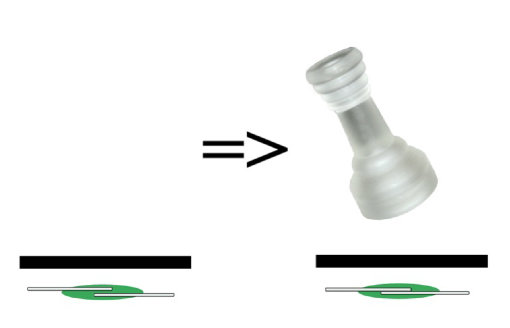
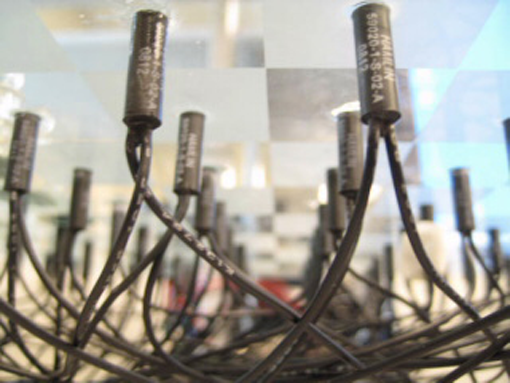
Figure 1: Reed Switches
As shown by Figure 1, Reed switches are normally open. However, when a magnetic field is brought close to them, the switch will close. We used these to connect the vertical output lines to the horizontal input lines. Figure 2 displays how we initially thought this could work.
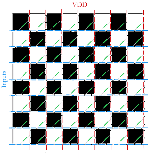
Figure 2: Chess Board Reed Switches
Unfortunately this setup does not work. We went through a few different polling methods before we settled on our final version. For more information on how we scanned for pieces, please see the Software Design section.
Communication and Display
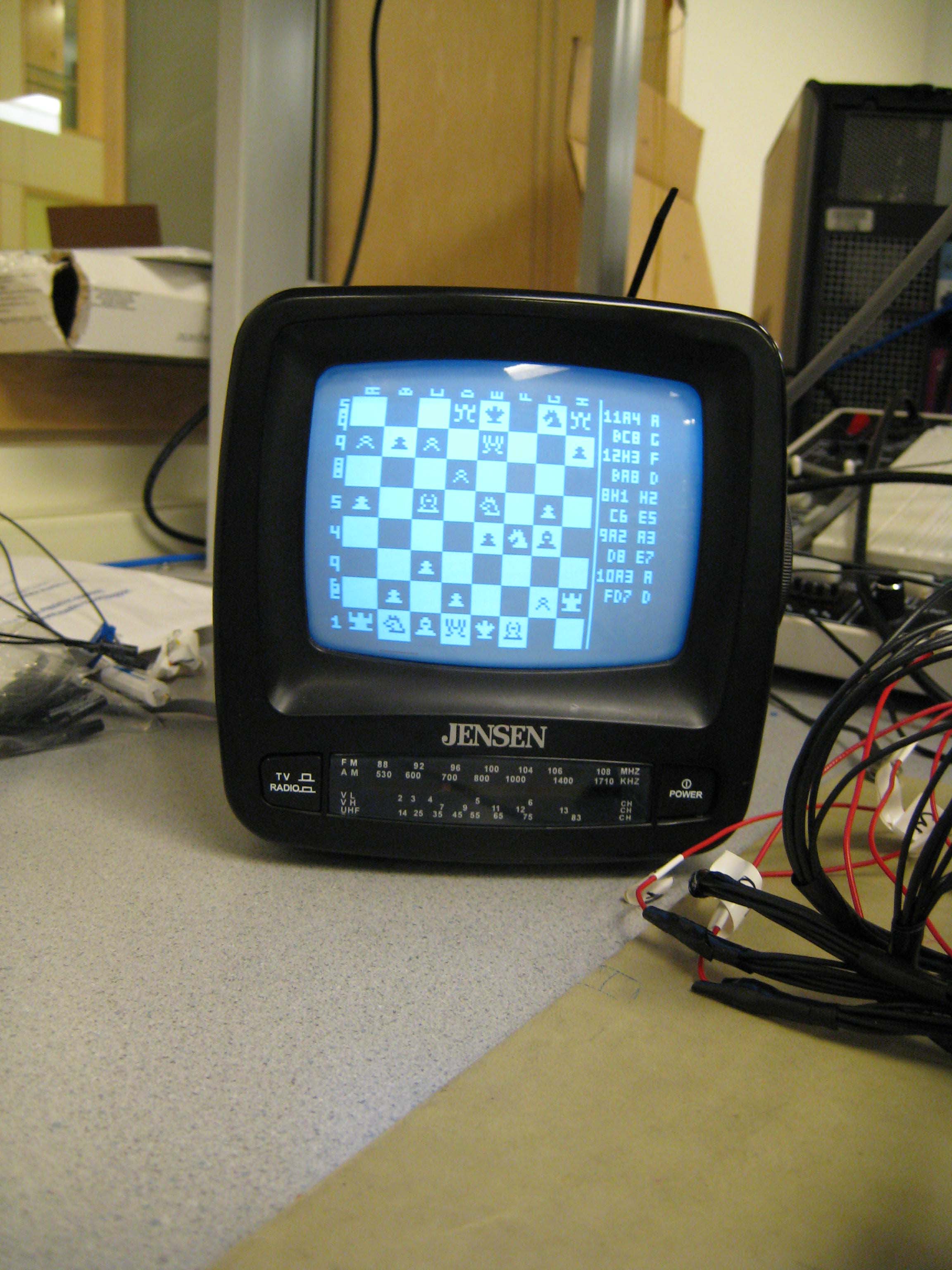
Our MCU connects to a computer through a serial connection. This computer then opens a socket with the computer that the other board is connected to and is used to transmit data back and forth between the two boards. We use a black and white TV set to show the full board, including the opponent’s pieces. Since all chess games start with the pieces in the same setup and only one move can be made during a player’s turn, it will be possible to keep track of where each piece is without having each generate a unique signature. By comparing the previous setup with the new setup after a move, we can determine which piece moved and if the move was legal.
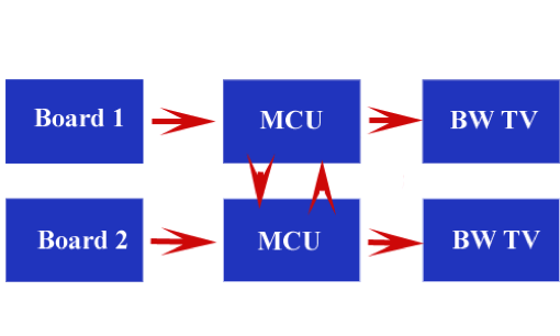
Figure 3: Block Diagram
Hardware and Software Design
Hardware Details | Software Details | Results
Hardware Details
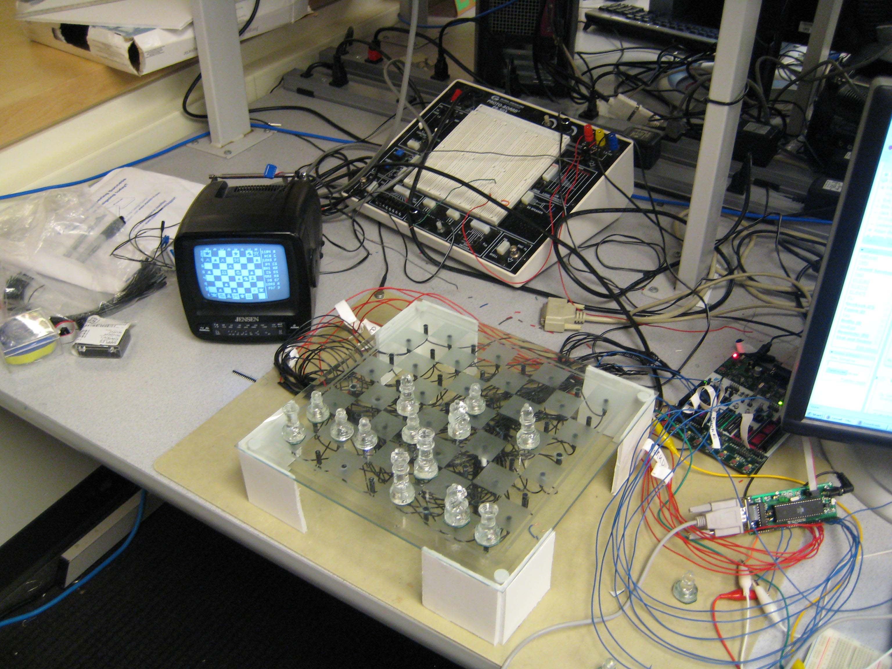
The main hardware component of our project was the boards that we made. In the end, two boards were made; one was converted from a glass chessboard and the other was constructed from foamcore. Each board had 64 reed switches attached to it. These switches were used to detect the presence of chess pieces on the board.
Main Operation Sequence
Each switch was located under one of the tiles on the board. When a chess piece with an embedded magnet was placed on the tile, the switch would go from open to closed. The strength of the magnets was just right, covering most of the tile but not interfering with adjacent switches. Each switch had two long leads attached to it. We took each row of eight switches and connected them to common input pin. Likewise, each column of eight was connected to one of the out put pins. To poll the circuit we set all of the output pins to high impedance except for one, which was set to ground. Since all of the inputs were pulled up to VDD, a closed connection from the low output to one of the inputs would pull it down. At the same time, a connection to one of the high impedance outputs would not affect the input voltage, and no piece would be detected. This setup allowed us to determine if a piece was present at any tile. We cycled through the outputs, setting one to low each time, and checked the inputs to see if there was connection to ground. Any connection meant that there was piece present on that tile.
This polling scheme led to one of our main obstacles. When we were first testing the board we found that a certain setup allowed the ground signal to pass to inputs that it was not supposed to be able to reach.

Figure 4: Ghosting Problem
An ‘L’ shaped configuration like the one shown above caused a ‘ghost’ piece to show up at the node that would turn the ‘L’ into a rectangle. At first we were puzzled by why this would occur. After spending some time investigating the matter, we discovered that the three closed circuits generated the following path:
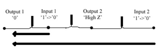
Figure 5: Short Circuit Path
To prevent this from happening, we had to place diodes between each input pin and the incident sensor leads. With diodes facing away from the pin, the high input was still able to be pulled down. However, the current from the second input pin could not pass through the diode and it was unable to pull any other inputs down. Once theses 64 diodes were heroically installed in each board the problem disappeared and we were left with functioning boards.

Figure 6: Short Circuit Solution
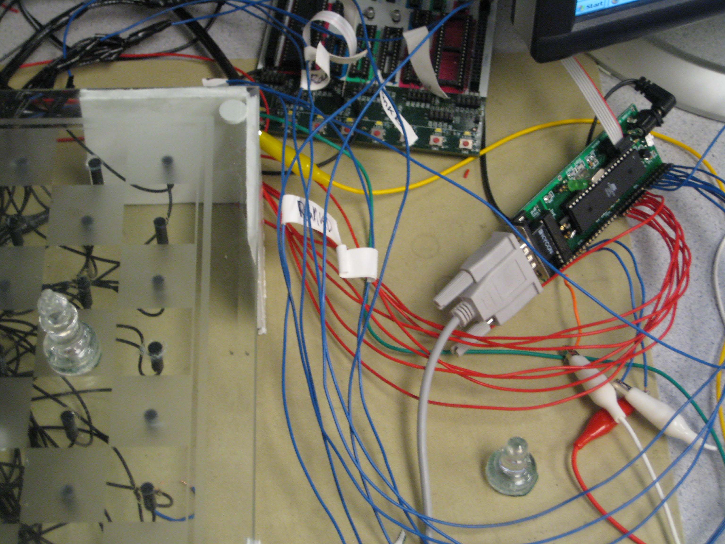
We also used two PCB boards with RS-232 serial communication functionality. These boards ran the MCU that polled the board, displayed the chess game on the BW TVs, and calculated the validity of moves. The serial communication was used to send valid moves from the MCU to a PC. The PC would then send the moves to another PC through a TCP/IP socket. This second PC would transmit moves that it received to its own MCU and would then communicate to the first PC and MCU in a similar fashion. This allows players to compete from two very spatially remote locations.
A serial interface was added to allow remote actuation of the gimbal mechanism and also to display useful messages for debugging. The USART is configured to run at 9600 baud, no parity, one stop bit, and no flow control. The remote_control function interprets key presses (WSAD) and moves the gimbal in the commanded direction. The adc_readout function displays the raw ADC values for each photocell to verify operation of the electrical circuit.
Software Details
Our C controller software consisted of several distinct parts. It used the video code from lab 4 (slightly modified to display larger characters and chess pieces) and chess piece bitmaps from a different group’s previous project (see conclusion) to display the game on our TVs. Our program used polling functions to communicate between the MCUs, and to scan the boards. We used polling functions (as opposed to interrupts) for serial communication because we did not want any code to interrupt the video display. Most of the code we wrote (over 800 lines) was for checking the validity of chess moves. These algorithms were not fast, our TV displays flickered each time a piece was picked up or put down. We found the flickering useful in testing, as it showed when a piece had successfully been detected.
Writing move validation algorithms was not easy in C, as many moves are verified as combinations of other moves. Castling, a move in which a king moves two squares, and a rook moves over the king, was particularly difficult to validate. There are many different conditions that must be satisfied before castling can be allowed. For example, every square between the king’s starting and destination point must be examined to see if it is threatened by the opponent’s pieces.
There were two principle software elements of our project. One of these was our C controller program, it ran on each MCU and was responsible for polling the board, check validity of moves, displaying moves on the TVs, and communicating moves over the serial connection. The other software element was our Matlab communication scripts. These forwarded data from the serial ports to each other.
When a game starts, the MCU program scans the board. It assumes the opponent will have all the necessary pieces, but it only displays the user’s pieces that it can detect. Before the first move is made, the user has the opportunity to wiggle or adjust pieces so that they are detected. Once the users are happy with their pieces, the Matlab scripts are initiated. Any sequence of characters entering the PC’s serial port followed by a terminator (we used ‘z’) is forwarded to the output of the other PC’s serial port. After five characters are transmitted, the direction of the forwarding changes.
When an MCU transmits or receives a move, it updates the screen to reflect the new position of the pieces on the board. It also prints the move (again in algebraic notation) alongside the board, for reference. After ten turns worth of moves (ten white and ten black) moves are overwritten starting from the top. Moves are numbered 0 to 99 to avoid confusion. Most games end before 100 moves. However, if games of 100 moves or longer are played, the first digit is replaced with a character. In this way, games of 390 moves are supported. There was not enough room on the screen for moves to be displayed with three digits. Games that reach 389 moves should be ended in a draw.
Our MCU program accommodates special cases. For example, when one of you pieces is taken, it understands that what it sees on the board is incorrect. Further input from the board is ignored until the piece is removed. Also, when you castle, you cannot make another move until the rook is in the proper place.
Results
After a lot of work, we finished our project. All of our initial goals were met and we even exceeded some of our initial plans. Since neither of us has worked with TCP/IP before, we were worried that it might be difficult to make Remote Chess really remote. However, with some of Bruce’s guidance and a little help from Thomas Craig we were able to write a Matlab program that imported Java to handle the serial and TCP/IP communication.
Both boards work wonderfully and we’ve removed all hardware problems that we encountered in development. A lot of work was spent soldering, taping, connecting, unsoldering, reconnecting, debugging, and testing the 256 leads that extend from our 128 reed switches. We were hit with a lot of unusual problems during development, but perseverance and an immense amount of lab time got us through it.
We also had issues with software. Our first few scanning routines failed for various reasons. Some had problems with pulling down the pulled-up inputs when there were a few in parallel. Other scanning routines suffered from coding issues like extra output lows resulting from shift operations. Luckily for us, we had built testing code previously. Due to this we had been able to work out the move checking code before we had to test the sensing code. This allowed us to isolate problems due to the scanning routines.
In the end it was all worth it when it came together and worked. Our Remote Chess set works wonderfully and we are very proud of the results of all of our hard work.
Conclusion
Remote Chess is safe and fun for everyone. With no large voltages present and no exposed wires, the game does not pose a hazard to its players. All connections were carefully soldered and covered in electrical tape for safety concerns. We really do not think that infants could swallow one of the chess pieces, so if you really need an ego boost you could play against a kid without worrying. Also, we use black and white images, so color blind people will not experience any difficulties playing our game. All in all, anyone who enjoys chess should enjoy our version as well.
In regards to the IEEE Code of Ethics, the ten points were followed. When we started the project, we were honest about what we planned to create. Through hard work we were actually able to go beyond the proposed abilities, but we we made the proposal in accordance to our best estimations. While working on the project we made sure to avoid conflicts of interest and did not take bribes. Work was done on the hardware to make sure that it presented no hazard to its players. Now that we are finished, we are posting this website so that others may benefit from our work and that we might receive feedback from the community.
Remote Chess exceeded our expectations. Detection and transmission was much faster than we had anticipated. That our project succeeded at all is extraordinary, and we owe thanks to all the people that helped us along the way. For the pictures of pieces that we displayed on our TV sets, we used the bitmaps created by the Spring 2007 group ‘Speech Recognition Chess’ by Kon-Hyong Kim (kk336), Tae Yong “Tim” Chung (tc228), and Kevin Jin-Ho Ham (kh272). For our remote serial connection, we were advised by Professor Bruce Land, and fellow student Thomas Craig. Most importantly, we owe our sensors to Hamlin Electronics, and Walter Zenczak in particular. He helped us select the type of Reed switch we used, and sampled us enough to make our boards. Without Hamlin’s generosity our project would not have made it under budget. We also need to thank Maxim-IC, who sampled us two MAX233CPPs, and Atmel, who has promised to send us two Mega32 chips. We would also like to thank our classmates Nate and Cathy, Nat for making new pieces for use from copper and solder to replace ones lost in the lab, and Cathy, for babysitting these pieces and naming them: a knight named Herman, and a pawn named Hamlin.
Throughout our project we were help by ECE 476’s TAs. We are especially thankful to Sam Lee and Rob Zimmerman. By talking to these TAs we were able to solve many of our problems. This class has been wonderful and we’d like to thank Professor Bruce Land for making the class what it is.
Appendices
Full schematics are available in PDF format.
Appendix 1: Budget | Appendix 2: Schematics | Appendix 3: Specific Tasks | Appendix 4: References | Appendix 5: Handmade Pieces | Appendix 6: Code | Appendix 7: Pictures
Appendix 1: Budget
| Part | Quantity | Cost | Total | Source |
|---|---|---|---|---|
| -- | -- |
-- |
$43 |
-- |
| Chess Set | 1 |
$7.00 |
$7.00 |
Salvation Army |
| Custom PCB Board | 2 |
$5.00 |
$10.00 |
ECE 476 Digital Lab |
| MAX233CPP | 1 |
-- |
-- |
Sampled from Maxim-IC |
| Mega32 MCU | 2 |
-- |
-- |
Sampled from Atmel |
| 16 MHz Crystal Oscillator | 2 |
-- |
-- |
ECE 476 Digital Lab |
| Passive Circuit Components | ~20 |
-- |
-- |
ECE 476 Digital Lab |
| RS232 Connector | 2 |
$1.00 |
$2.00 |
ECE 476 Digital Lab |
| DIP Socket | 4 |
$.50 |
$2.00 |
ECE 476 Digital Lab |
| Power Supply | 2 |
$5.00 |
$10.00 |
ECE 476 Digital Lab |
| Black and White TV | 2 |
$5.00 |
$10.00 |
ECE 476 Digital Lab |
| Foamcore | 1 |
$2.00 |
$2.00 |
The Cornell Store |
| Adhesive | 1 |
-- |
-- |
Previously Owned |
| Sharpie | 1 |
-- |
-- |
Previously Owned |
| Reed Switch | 128 |
-- |
-- |
Sampled from Hamlin |
| Neodymium Magnets | 16 |
-- |
-- |
ECE 476 Digital Lab |
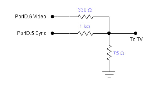
Appendix 2: Schematics
MCU output to TVs:
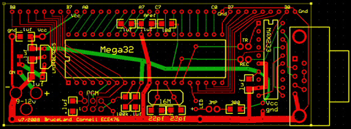
Custom board for our MCUs:
Appendix 3: Specific Tasks
Erik Jarva did almost all of the soldering: he made two PCB boards, and fixed both our chess boards by adding a total of 128 diodes to stop short circuits. He wrote the Matlab scripts that connect the PCs and forward the serial data from MCU to MCU.
William Baughman wrote almost all of the C code, including the verification algorithms and communication. He put magnets in most of the pieces, and constructed the stand for the glass board.
Both partners constructed the foam board, and spent many hours debugging code and testing the verification algorithms.
Appendix 4: References
We used the 59020-1-S-02-A Reed Switches from Hamlin Electronics:
We used two MAX233 bridges by Maxim-IC:
We used Digikey to buy our magnets:
Atmel sampled us to Mega32 MCUs:
The very important CIT Atmel Mega32 Data Sheet
We used chess piece bitmaps from the Spring 2007 ECE476 project group "Speech Recognition Chess":
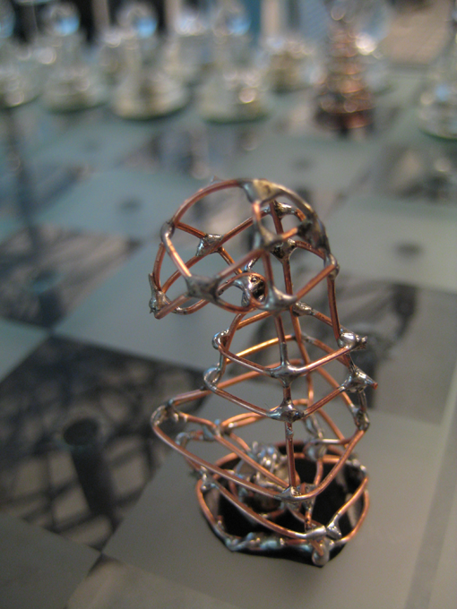
Appendix 5: Handmade Pieces
While working on the project, two of our pieces were lost: a pawn and knight. Although we looked for them vigilantly, they were never found.
Luckily for us, one of our classmates, Nathan Chun, made us two replacements out of copper wire and solder. We owe him a big thanks for his contribution to our project. Below are some pictures of his awesome work.

Appendix 6: Code
MCU Code:
C File Chess Code Header Video Code Header
Matlab Communication Code: