
Introduction
TouchSynth : an intuitive waveform and rhythm generator.
The system uses a touchpad to interface with the user, allowing for the creation of many tones and patterns similar to synthesizers used by DJs. TouchSynth stores and plays up to four unique and independent waveforms as well as the patterns of four different drum voices and allows for the manipulation of each without affecting the other. Tempo and pitch are easily modified to create chords with a variable speed background drum track.
This was a five-week design project for ECE 476 at Cornell University.
Nathan Chun nic4
John Sullivan jps79
High Level Design
Inspiration
The inspiration for this project came several sources.
Being a musician, Nathan is interested in the physics behind music. Every sound produced by a musical instrument is a repeating waveform. Depending on the shape of the waveform, different sounds are perceived. Being able to draw waveforms on a touchscreen will allow non-musical individuals to experiment with different waveforms to explore how different shapes produce different sounding tones.
The idea for adding rhythms to the project came when one of the TAs mentioned the idea of using the touchscreen as a synthesizer, much like the ones that DJs use to play and mix samples into their music. Adding a simple rhythm track of four samples allows for individuals to play around with different rhythm patterns to compliment the tones being produced.
Thus the idea of a touchscreen synthesizer was born.
Overall Concept
The synthesizer is a touch screen overlaid over a piece of paper with the layout of the synthesizer. Since the touch screen is made of transparent glass and film, placing the paper underneath allows for us to only operate the touchscreen as an input rather than have an interactive display which would make things much more complicated.
The layout has three main sections; tones, rhythms, and the master controls.
In the tones section, four smaller partitions allow the user to play, pause or stop the existing waveform or alternatively, record a new one. This waveform is played back directly from the ATmega32 chip using the Direct Digital Synthesis (DDS) technique which involves a pulse-width modulation output signal. Finally, the user can adjust the frequency of the tone being played in half-note increments by tapping either the left or right segments of the FREQ partition. Tapping the right half increments the frequency whereas tapping the left decrements it.
The beats section is very similar to the tones section except for two items. The first is the removal of the frequency control since drum pulses do not have frequencies. The second is the change in operation of the record button. Instead of having the user draw an input, each time the user taps that section, a beat is added to the 16-beat table so that the next pass through, the program will remember that the user has entered in a beat and play it at the appropriate spot. To produce the sounds, four audio recording chips were used to store the four sounds. The audio output from the four Chipcorders and the PWM from the ATmega32 were summed together and outputted through a 1/8 TRS jack.
Background Mathematics
Interpolation
In order to compensate for either inaccuracies in the touchscreen readings, missing points due to the touchscreen resolution, or for the user not pressing down hard enough on the touchscreen to register, an interpolation function was used to fill in the missing pieces. The function used two points of known x and y coordinates and linearly interpolated between the two by using equation (2) derived below:
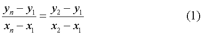
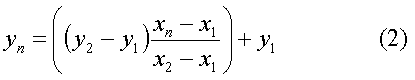
where the two known points are at (x1, y1) and (x2, y2) and the unknown point is at (xn, yn).
Frequencies
In order to get the proper increment for the frequencies, a reference frequency of 440 Hz corresponding to the first A above middle C was set. For each half step above or below, we used equation (4) shown below to find the proper increment:
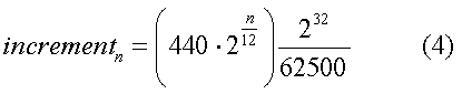
These values were then hardcoded into the program in a reference table.
BPM
To get appropriate timing values for the drum beats, the fastest and slowest values that seemed reasonable were experimentally derived and found to be 75 and 250 counts per reset. With those values, we found 23 intermediary values that were spaced evenly along an exponential scale. The equation (5) that we used is shown below:
These values were then hardcoded into the program in a reference table.
Hardware / Software Tradeoffs
In order to relieve some of the burden of processing sounds from the microprocessor, as well as allow for different sounds to be easily recorded onto the hardware, four individual audio units were used to produce the drum beats. Having these units makes importing user-created sounds much easier than if the user was required to know how to encode the sound in an audio generating algorithm such as differential, pulse-code modulation (DPCM), which was used in a previous project, or Karplus-Strong, which was used in at least two other projects that produce drum beats this year.
Standards
From all the research we did, the tip, ring, sleeve configuration for the audio plug does not seem to be a defined standard, but rather, an industry standard that manufacturers agreed on for production. In the same fashion, we use a modified stereo standard for audio output. Generally, for a stereo signal, the tip and the ring of the 1/8 audio plug are the left and right channel respectively, but for our purposes, we connected both to a single signal so that both channels get the same information and thus play the same sound.
(wikipedia.org)
Hardware Design
Touchscreen
The touchscreen construction is a relatively simple 5-wire resistive system. Four of the output wires are connected to each of the four corners of the rectangular screen, the fifth is connected to a conductive film overlaid on a resistive grid. By driving the output wires corresponding to two adjacent corners high and the other two corners low, a voltage gradient is established across one axis of the touch screen. When the film is pressed, the fifth wire reads the voltage at that point. The closer a touch is to the corners being driven high, the higher the output voltage read. In order to read the second axis, the inputs to the corners must be driven such that the voltage gradient is in the perpendicular direction. By alternating the two gradients, the two coordinates can be obtained with high accuracy. Furthermore, we found that only two corners needed to be switched to achieve the two voltage gradients needed for a coordinate.
(Manufacturer's Animation)
We found that the settling time for a touch was on the order of a second. After consulting with the TAs, a 1kΩ pull-down resistor was added. This reduced the falling time to two milliseconds which was fast enough for our purposes. The touchscreen was then debounced in order to reduce the risk of catching a false touch caused by the falling output signal.
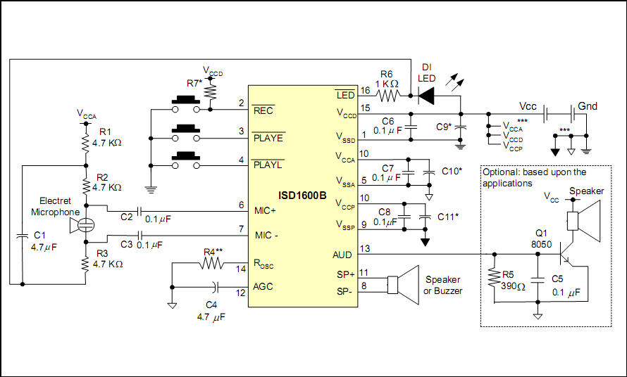
Chipcorders
The four chipcorders were wired up to the manufacturers specifications as best as possible. To record sounds onto the chipcorders, we attached buttons to the circuit that connected the record pin of a chip to ground. The audio jack was then connected to the microphone input to the pin and a set of earbuds was plugged into the audio jack. Used as a cheap microphone, the earbuds took the sound that we made (mostly vocal percussion) and created an audio signal for the recording. Those same earbuds were used initially to test if the voice recorders played back properly, then to test if the voice recorders and the DDS signal from the microprocessor both played when mixed together.
Software Design
The final program can be divided up into three modules; touch, waveforms, and beats.
Initially, the program sets up and initializes all of the ports, variables and modules such as the timer, Analog to Digital Converter (ADC), and the Digital Direct Synthesis(DDS) modules. The program then proceeds into the main loop.
Every three milliseconds, the inputs from the touchscreen, which is constantly polled, are parsed. The raw x-y coordinates from the touchscreen are compared against a table of preset indices to map the raw data to a set of index coordinates using a 2-d binary search, with each index corresponding to a single column or row of partitions on the interface. Once the touchpad has sensed which partition the user intended to touch, the parsing function reads the indices given and takes appropriate action.
The top section of the touchscreen containing the top three rows of partitions is the area that deals with controlling the waveform outputs. The four waveforms operate independently of each other, each having its own set of waveform variables and thus, one can be set to play, pause or stop without affecting the performance of the other three. If the user chooses to record a new waveform, then the program enters the record function. To record a new waveform, a temporary waveform array is first cleared, then written to, a constant stream of input from the touchscreen written to the temporary array as soon as they are read. Once the user touches the enter partition on the bottom right of the touchscreen, the function takes the inputted data and then interpolates it to fill in any missing areas caused by undersampling of the touchscreen input, a light touch by the user, or partial data from the user. The interpolation function multiplies two arbitrary 32-bit longs then divides the result by another arbitrary 32-bit long in order to maintain accuracy in calculation. The algorithm may seem awkward and bulky, but since there are no deadlines to meet, and the calculations are finished within seconds, we felt that it was alright to keep. Finally, once the interpolation is finished, the temporary array is copied to the appropriate waveform table.
Controlling the playback, pausing and stopping of the waveforms is relatively simple. To play a waveform the increment is set from 0 to a value in the reference table. This starts the accumulator running and program begins to cycle through the appropriate table, setting the output compare register (OCR) to the stored PWM value. To pause, the increment and accumulator are set to 0, suppressing playback, but still keeping the PWM values stored for later use. To stop, the PWM table is completely cleared. Lastly, the user may touch either the right or left side of the frequency partition to increment or decrement the frequency of each individual waveform.
The middle section of the touchscreen, the two rows right below the waveform module, is the beat section of the synthesizer. The user can play, pause or stop and clear the current rhythm or add beats to the pattern by tapping the record partition on the appropriate pad. Like the waveforms, the four sections operate independently of each other, using a mask to selectively index certain bits in the beatenable and beattable variables.
The control of the beat module is done through a variable, beatenable, that is checked every time a beat is supposed to be played. The control variable, beatenable, like the increment and accumulator for the DDS, is independent of the play data for the module allowing for the output to be suppressed but not cleared. Only when the user wants to stop the beat pattern is the data erased.
Taking up the last two rows are the master controls for the synthesizer. The majority of the row is taken up by the tempo bar which acts much like the frequency control for each waveform, although this control affects all of the beat synthesizers en masse. The user may tap the right or left half of the tempo bar to increment or decrement the rate at which the drum beats are produced. To the right of the tempo bar is a set of partitions. Since the record functionality is very individual and can only run one at a time for each of the other eight modules, we replaced the record module with a confirm record partition which the user touches after finishing recording a waveform. When the user touches the pause, play or stop partitions in the master controls, it is as if every partition of that type were touched at once.
Results
In testing, instead of using the chipcorders circuitry, the active low signals were driven to the LEDs on the STK500 board. There, they worked perfectly, pausing, replaying, stopping and recording as ordered. The results from the chipcorders themselves were less than stellar. The manual loading of sounds onto the chip was convenient, but it produced sub-par quality sound. Also, the fact that the trigger to play was only on for half of each actual beat in order to allow the chipcorders to turn off before the next beat cut the sounds short dramatically, making it difficult to distinguish beats from each other.
From experimental results, we concluded that the output pattern for the touchscreen was linear in both axes and orthogonal in the axes. This allowed for the touchscreen to be easily mapped to a series of partitions. The output voltage, though, was not rail to rail, possibly because of internal resistances outside of the active area. Until recently, the grid has become more and more skewed until what should have been parallel lines were at significant angles to each other. The problem was caused by the fact that the ADC line had several medium frequency oscillations on it, since PORTA was being used for the ADC as well as to create the voltage gradients on the touchscreen. By switching the rail toggling to PORTC, the problem was completely eliminated.
The DDS module worked wonderfully. Scoping the output from the PWM port, the waveform displayed on the oscilloscope closely resembled what drawn on the touchscreen. The output was relatively smooth and well defined.
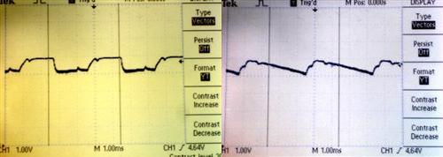
Left: Drawn Square Wave
Right: Drawn Sawtooth Wave
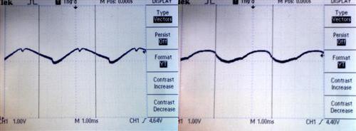
Left: Drawn Triangle Wave
Right: Drawn Sine Wave
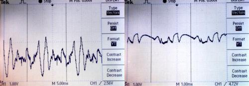
Four Waves Summed Up
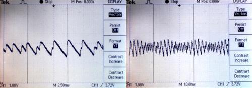
Left: Two Sawtooth Waves Summed Right: Interference Beats Created By Two Summed Sawooth Wave
Conclusions
Looking back on how this project was done there are several things that we would have done differently. Instead of using an external system to produce the sound, the drum noises could be done on the microprocessor. This would reduce the complexity of the circuit as well as allow for a more enclosed system.Overall, after the blood and sweat and tears that poured into this project, not to mention the multiple solder burns, it appears to be a success. The touchscreen properly interfaced with the microcontroller, selecting the proper partition with a good deal of accuracy. The DDS waveform generator worked wonderfully, producing full chords with several different sounding notes. Even the drum beats produced rhythm, albeit with a good deal of noise that is mostly static and very little actual tone.
Ethical Considerations
We followed the IEEE Code of Ethics throughout the planning, design and implementation of the project to the best of our ability. The project does not compromise the safety, health or welfare of the public or the environment as far as we know. We avoided conflicts of interest as much as possible and were resolved as soon as possible when they did happen. The claims that we have stated in the previous document are accurate and realistic. None of the results presented have been altered in any way. Bribery was not and will never be involved in the creation of the project. Through this project, our understanding of the technology used, its appropriate application, and potential consequences was improved through experimentation and testing. Technological competence and experience was maintained and fully disclosed when undertaking tasks for others. We willingly accepted criticism of technical work by any and all parties and errors pointed out by others were corrected with credit properly given to those parties. In turn, we provided constructive criticism of and assistance with other projects as needed. We treated everyone that we encountered during the development of this project fairly regardless of such factors as race, religion, gender, disability, age, or national origin. We avoided injuring others, their property, reputation, or employment by false or malicious action. We assisted colleagues and co-workers in their professional development and to support them in following this code of ethics.
Appendices
Source Code
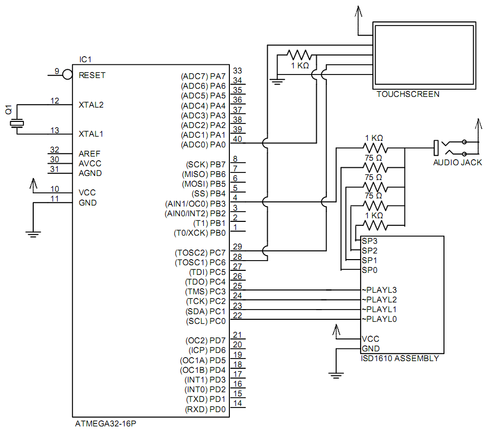
Schematics
Parts List
| PART NAME | PRICE | QUANTITY | SUBTOTAL | SOURCE |
|---|---|---|---|---|
| -- | -- | TOTAL | $62.84 | -- |
| STK500 | $15.00 | 1 | $15.00 | ECE 476 Digital Lab |
| Mega32 | $8.00 | 1 | $8.00 | ECE 476 Digital Lab |
| 12V Power Supply | $5.00 | 1 | $5.00 | ECE 476 Digital Lab |
| 2-pin Jumpers | $1.00 | 1 | $1.00 | ECE 476 Digital Lab |
| White Board | $6.00 | 1 | $6.00 | ECE 476 Digital Lab |
| Solder Board | $2.50 | 1 | $2.50 | ECE 476 Digital Lab |
| SOIC Carrier | $1.00 | 4 | $4.00 | ECE 476 Digital Lab |
| SIP Pin | $0.05 | 64 | $3.20 | ECE 476 Digital Lab |
| ISD1610 | $4.41 | 4 | $17.64 | Ordered from digikey.com |
| Header Pin | $0.05 | 10 | $0.50 | ECE 476 Digital Lab |
| 12.3" Touchscreen | $0.00 | 1 | $0.00 | Sampled from Bergquist |
| Red LED | $0.00 | 4 | $0.00 | ECE 476 Digital Lab |
| 2N3904 | $0.00 | 4 | $0.00 | ECE 476 Digital Lab |
| Audio Jack | $0.00 | 1 | $0.00 | ECE 476 Digital Lab |
Work Distribution
Nathan:
- Wiring
- Soldering
- Circuit debugging
- Shopping for parts
- Negotiating for parts
- Programming
- Project Report
John:
- Circuit debugging
- Shopping for parts
- Website Design
References
Data Sheets
Vendor Sites
Acknowledgements
To Bruce Land, thank you for providing your insight and for bringing your passion for the class into lab every day.
To the TAs, thank you for staying up late to allow us to work in the lab and for putting up with us even when things get somewhat bizarre due to the solder fumes, caffeination, lack of sleep and tear-inducing frustration brought on by the long hours.
We would like to extend a special thank you to the Bergquist Company Touchscreen Division for their generous donation of the touchscreen.
Photos
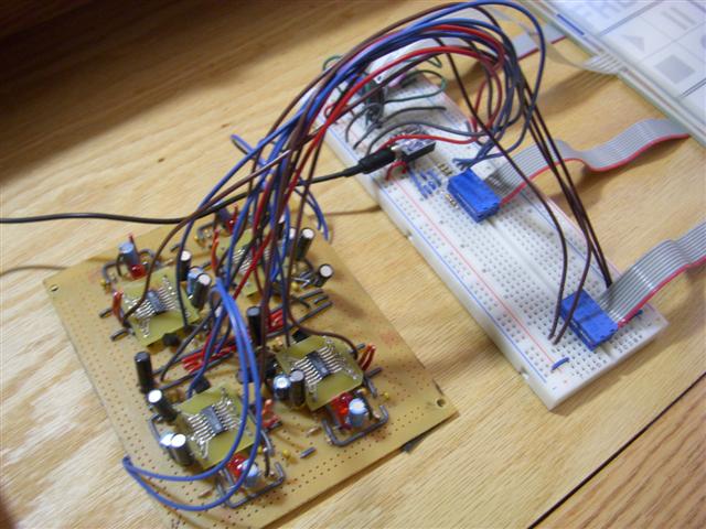
Chipcorder Circuit
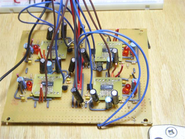
Chipcorder Circuit
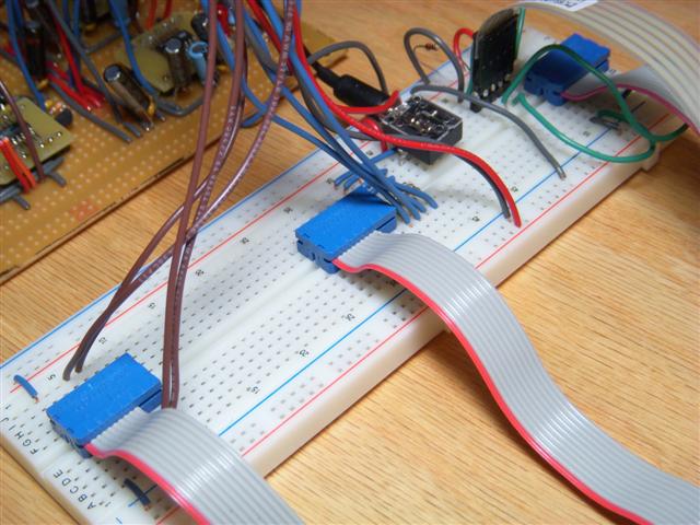
Solderless Breadboard
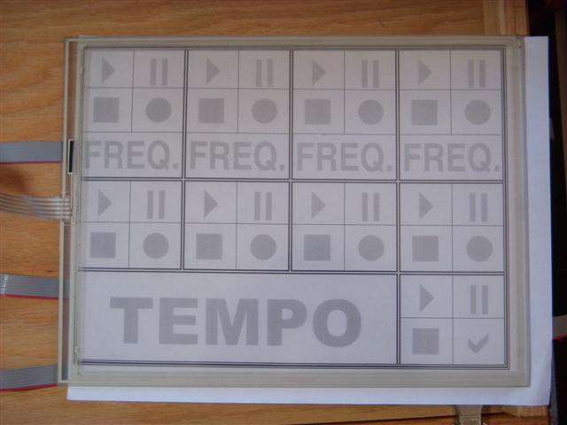
Touchpad with Underlay
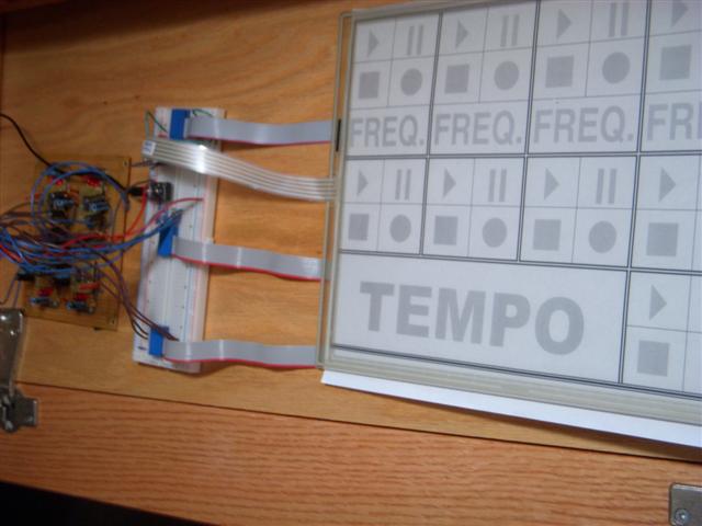
Whole Circuit

The touchpad is CLEAR!!!
More Information
Please free to contact either of us at (nic4) or (jps79) both @cornell.edu