by Parker Evans (pae26@cornell.edu) and Raymond Chang (rwc28@cornell.edu)
Introduction
High Level Design
Program/Hardware Design
Results
Conclusions
Appendix A - Program Listing
Appendix B - Hardware Schematics
Appendix C - Budget
Appendix D - Division of Labor
Resources
Our project, in one sentence, is an orientation independent 3D LED display. We were inspired by various videos on youtube of similar cubes but also by the idea of creating an interactive 3-dimensional display.
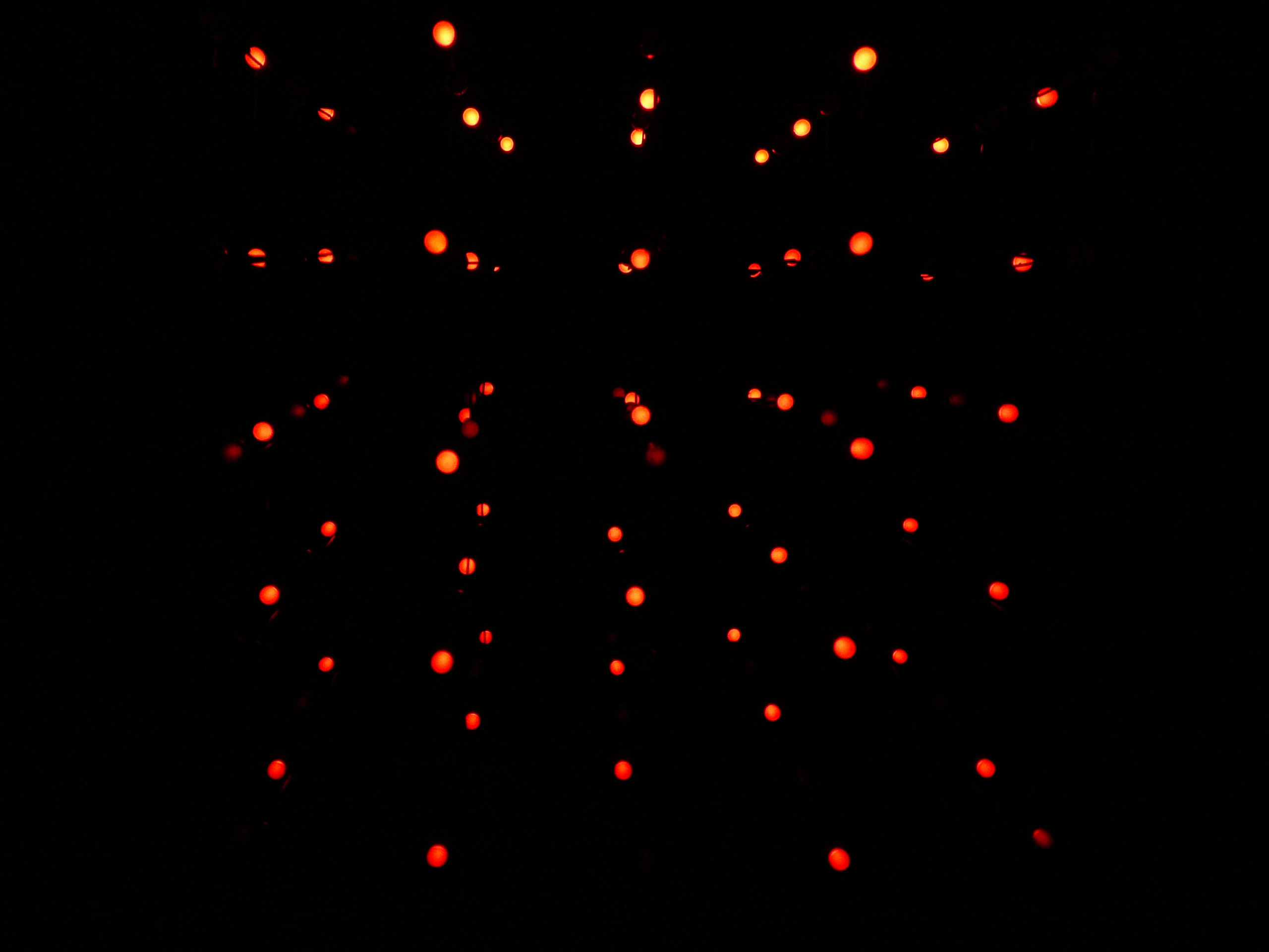
We built a 5x5x5 LED cube display and controller board which interfaced the cube to a Mega32 microcontroller. We can display a wide range of low resolution 3D images or animations on our cube and we use an accelerometer to detect the horizontal or vertical orientation of the cube and adjust the display so that it remains upright even if we turn the cube sideways. The cube was used to display a message ("ECE476 FINAL PROJECT DEMO") and display a little light show animation.
We received inspiration for our design when we saw one of the many videos on youtube of 3D LED cubes. We thought the idea of a 3D display was interesting yet challenging given the budgetary and time constraints and we also thought we could take the idea one step further (this extra step ended up being the orientation adjustment using an accelerometer).
One of the main considerations when first designing our cube was deciding how large to make it. Obviously more LED's would give better resolution and allow us to display some more interesting images but at the same time we were limited by how large of a cube we could fabricate in the given time and even more so by how many LED's we could reasonably control given the limited number of port pins and the limited processing power of the Mega32. We eventually settled on a 5x5x5 cube as a reasonable trade off between size and practicality, however, we do invite future groups, and others interested, to attempt to build a bigger cube given similar time and budget constraints (we suggest 8x8x8 since it gives you a nice round 512 LED's).
The next major consideration was how we would control all of the LED's. A 5x5x5 cube made for 125 LED's which was far more LED's than ports on the Mega32. We originally developed a method of controlling each LED individually that is much like the method used in common LED drivers. The method involved sending a serial bit stream that represented the state of each LED into a 125 bit serial-in parallel-out shift register. After shifting in the state of each of the 125 LED's we would then latch the value of each bit using 125 flip flops and drive each LED off of the output of a flip flop. This method required only 3 ports pins (one for the serial bit stream, one to clock the shift register, and one to clock the flip flops) and was very fast since we could clock the shift register at upwards of 1 MHz and theoretically update all the LED's in a couple hundred microseconds. Theoretically this method seemed very fast, however, practically this method was extremely inefficient.
The main problem with controlling each LED individually was that to do so we would need to run at least 1 wire to each and every LED. This problem quickly got out of hand; at the bottom of the cube we would have at least 6 wires running off of each of the 25 columns. All of these wires would have made for an aethstetically unpleasing cube and present the question of how we would route all these wires together and fit them into the base of the cube. We realized we would need to wire the LED's together in a way that we could address them individually without having to run a separate wire to each one. This was a tricky problem since a typical addressing scheme such as selecting a column, then a row, then a level would have the undesirable side effect of lighting more LED's than we wanted.
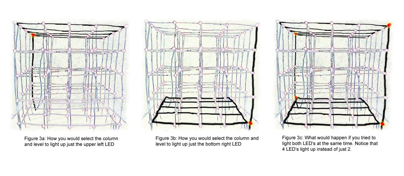
After some thought and search, we finally found this website which gave us a great method of how to do it. The tutorial showed us that we could in fact address LED's one at a time without having to run a ton of wires. To do so we would connect all of the up and down columns of LED's to the same positive terminal (25 columns total, with 5 LED's each) and then connect all of the horizontal levels to the same 'ground' (5 levels with 25 LED's each). To select a single LED we would apply 5V to the column in which the LED is located and then ground the level that it is on. This way using only 25 control lines for the columns and 5 control lines for the grounds we could select each LED individually. However, this still results in the previous problem of lightning extraneous LED's accidentally if we try to light more than 1 LED at a time. As illustrated in Figure 3, if we wanted to light just the first LED in the top level (back left corner) and the last LED on the bottom level (front right corner) we would set the 1st and 25th columns high and then ground the top and bottom levels. However, if we do this, instead of just having 2 LED's lit we would have 4 (top and bottom of back corner and top and bottom of front corner). To get around this we only try to light LED's in one column at a time. To display images that have LED's from multiple columns lit we cycle through each column at a fast rate (about 62.5Hz) to make it appear as though more than one column of LED's is on at the same time.
Hardware Description
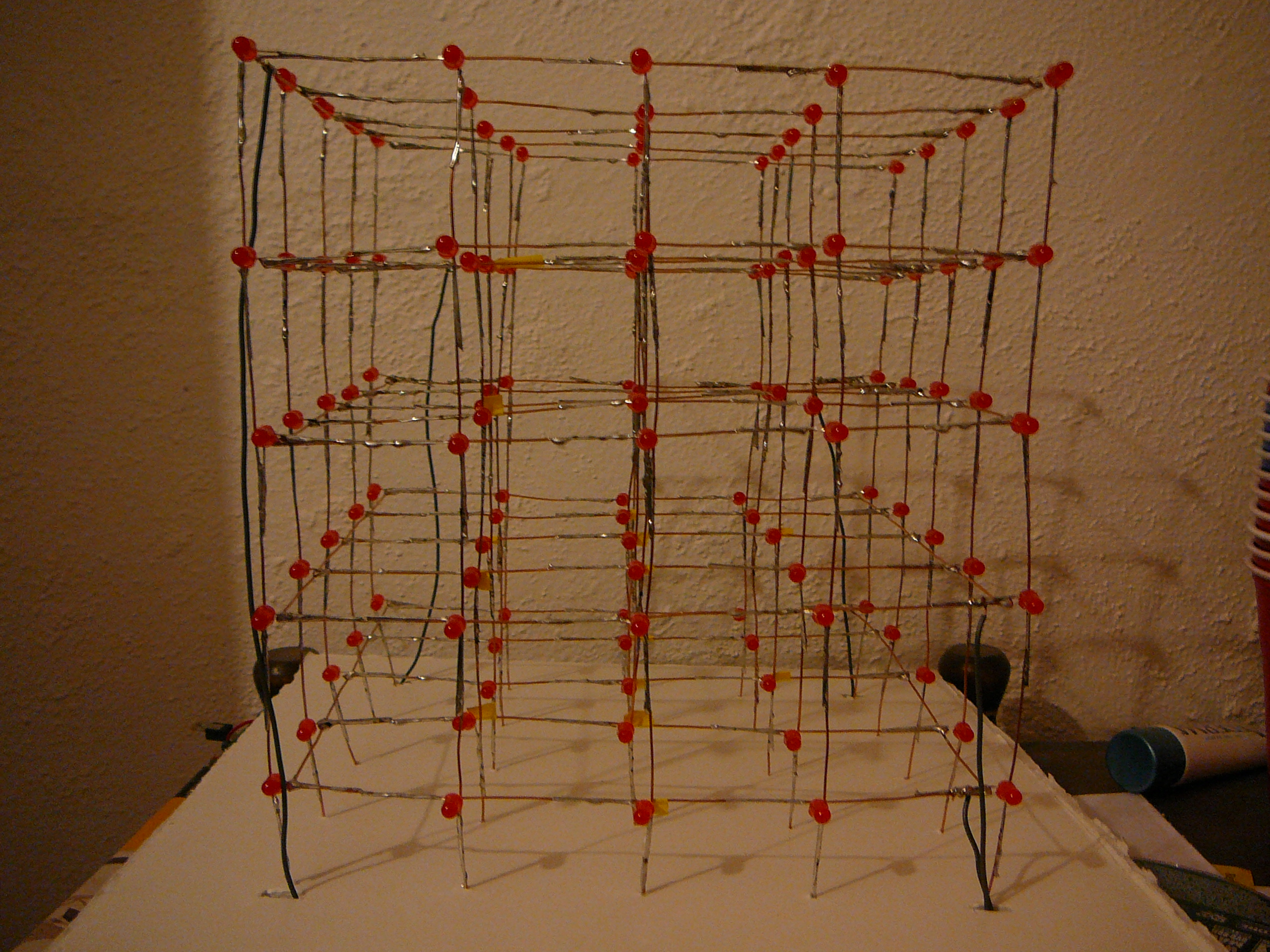
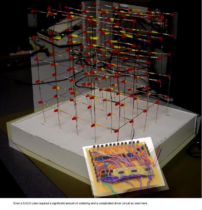
There was a lot of circuitry that had to be constructed in order to realize this project. First, we had to build the LED cube itself which actually turned out to be a much more difficult task then we first anticipated due to the shear number of LED's. We built each horizontal 5x5 plane individually by laying the LED's flat on top of wire and soldering all the negative terminals of the LED's onto the wire and leaving the positive terminal hanging. This essentially connected all the negative terminals of the LED's in the same level to the same ground plane. We then had to carefully solder the 5 horizontal planes together by first mounting them on the side of a cardboard box and taping them into place in a upright position and then soldering 1 wire to connect all the LED's in a vertical column together for each of the 25 columns.
In addition to building the LED cube itself we also had to design and build our own custom LED driver circuit. This circuit had to take inputs from a limited number of microcontroller pins and decode them into something that could control the cube. If we had simply taken the input of each column and each ground level directly from a microcontroller pin this would have taken 30 pins which would have taken up most of the 32 port pins of the Mega32 microcontroller. This would have been alright for our final application (which only needed two extra pins for the accelerometer input) but would make it hard for future projects to utilize our design. Instead, we decided to come up with a clever way to decrease the bus size and simplify the interface between the driver and the microcontroller.We created a decoding circuit (Figure 1) that could control 24 columns using only 5 pins. The remaining 25th column and the 5 ground levels were controlled directly from the microcontroller; this resulted in using a total of only 11 pins to control the entire cube.
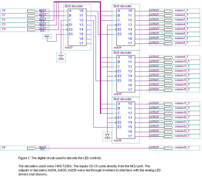
The first two bits of the 5 control lines feed into the first decoder (inst37). This decoder acts as a control that can select to enable any one, and only one, of the other 3 decoders. There is also a fourth option in which none of the output decoders are enabled which we use as a way to turn off all the LED's in the cube. The remaining 3 control lines feed into the 3 output decoders (inst34, inst35, and inst36). The outputs of these decoders feed directly to the columns; since only one output of any given decoder is high at a time, and only 1 of the output decoders is enabled at any given time, it is only possible to turn on 1 column at a time. This is highly favorable because, as shown in Figure 3, attempting to drive more than one column high at a time results in the unwanted lighting of additional LED's. Basically using this decoding scheme we can select any of the first 24 columns simply by sending the binary number of the column (the top two bits being a control for the master decoder and the bottom three being the input to the selected decoder).
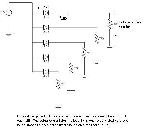
After completing the design of the digital circuit we were ready to connect it to our LED cube, however, before we did, we realized a glaring problem. The output from each pin of each decoder was to drive an entire column of LED's. This meant driving as many as 5 LED's in parallel, each drawing around 40 mA of current (Figure 4), for a total of 200 mA of current, however, the maximum current output of the decoder chips was rated at only 25 mA which would not be enough to drive even 1 LED, let alone all 5. Additionally, the port pins of the microcontroller were originally going to serve as the ground plane for all the LED's but we realized that they could in no way sink the amount of current that we needed to sink. To account for this we had to design a LED driver circuit which still used the outputs of the decoders and the microcontroller to control each column and the ground planes but drove the LED's through an external power and ground.
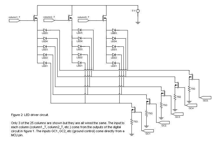
To control the LED's using the outputs of the decoders we used 25 pMOS transistors as high side switches and 5 nMOS transistors as low side switches (Figure 2). The pMOS transistors use the output of the decoder circuit as a sort of enable and supply the LED's with 5V when they are turned on. However, since pMOS transistors turn on with a low gate to source voltage, and the decoders we used were active high, we had to feed the output of the decoders through inverters before we connected them to the transistors. In a similar way the MCU ports are used to control nMOS transistors that connect the LED's to ground, however, since the control comes directly from a port pin there is no need for inverters here. Another problem that we encountered involved the amount of current that we could drive. The power now comes directly from a 5V regulator that is rated to supply at least an amp of current, which was more than enough, but the pMOS transistors that we used are only rated to supply 160 mA of continuous current. This meant that we would still have trouble driving all 5 of the LED's at the same time since each of the 5 LED's would try to draw 40 mA of current for a total of 200 mA. In order to get around this we employed a trick in the software that, instead of turning on all 5 LED's at the same time, would turn on the bottom 3 LED's first and then turn on the top 2 LED's.
Another concern, that is a direct consequence of our lighting scheme, is the timing. Since we need to strobe through a series of LED's to make it appear as though more than one LED is on at the same time we had to be careful about the amount of time that it takes to cycles through all of the LED's (refresh rate) and the time that we hold each LED on for (duty cycle). We wanted to try to keep each LED on for as long as possible since a longer duty cycle would make for brighter LED's. However, holding each LED on for longer would mean that it took more time to cycle through all the LED's and if this refresh rate was too slow then you could see a noticeable flicker. After some testing we decided that we wanted to cycle through all the LED's every 16 ms giving us approximately a 62.5 Hz refresh rate and eliminating any visible flicker. This meant that in 16 ms we would need to cycle through all 25 of our columns and for each column, hold the bottom three LED's that are currently lit on for a time, turn them off, and then hold the top two. We found that we could hold each of the 50 sets of LED's (top and bottom of each of the 25 columns) on for 200 μS and still meet our refresh rate requirements; each "frame" would take 10 ms to render leaving us with 6 ms of grace time to perform any necessary calculations for the next frame.
Software Description
The control software for the LED cube has a very simple structure.
First we initialized two flash arrays with pre-rendered columns for all possible digits and letters so that we could look these up easily for string display on the cube. In our case we could have just hard coded the string since we have only one intro string, but we decided to do this and use an initialization routine so that this could perhaps be utilized in future projects that attempt an LED cube and want to display text. It also saved some memory space.
We made an initialization routine that we call at the very beginning of the main function to set up the directionality of the ports that we used to control the cube. We basically just needed the bottom two bits of PORTA for our analog to digital conversion to be inputs for the two accelerometer lines, all of the port pins of PORTC and the bottom 3 port pins of PORTB to be output to control the lighting of the cube. The actual layout of pins are described in detail in the comments of the code in the initialization routine. We set up timer 0 to reset on compare-match with a prescaler of 64, set the OCR register to 249, and enabled the compare-match interrupt. This gave us an interrupt that triggered once per millisecond. With this millisecond time base, we could schedule a task precisely. We also initialize a counter for scheduling our task. We initialize the analog to digital converter to run at 125KHz, to first convert the 0 channel when a conversion is started, and to interrupt on conversion done so that we can do two conversions in a row easily. We then call our initialize sensors routine to initialize the bias values of our accelerometers and then our initialize intro routine to initialize an array of column values for use in displaying our introduction string. Finally, we initialize our state variables and start a conversion of the accelerometer values.
The calibrate sensors routine does just what its name suggests. Assuming the cube starts standing on its base (up and down orientation), we figure out the zero bias of both of the sensors. We simply do three conversions of each of the two accelerometer values and divide by three to get the average value. We save these values as our x and y accelerometer conversion biases (to be subtracted from the reading when we do future conversions).
The analog to digital conversion done interrupt service routine is used to do two consecutive conversions (of the x and y accelerometer values) quickly without slowing down the rest of the program or doing some other more complicated coding trick. We wanted the two conversions values to be done at very similar times and available together. We used a state variable to keep track of which channel we were converting, and checked it in this routine. If it is the first of the two, we grab the conversion value, change the analog to digital multiplexer to multiplex the next channel, change the state variable to reflect that we are converting the next value, and initialize the next conversion. When this next conversion gets back to the ISR, we save the conversion value and set a global flag which signals that the conversion data is ready so that the rest of the program can use the conversion values.
We have only one task in the software which is our display task. It is scheduled once every 16 mS using a counter that counts down from 16 in our millisecond interrupt tick (and a simple if statement in the main loop which checks for when the counter becomes zero). This delay gives rise to a calling rate of 62.5Hz which is well above the refresh rate of a display that a human eye can perceive. Thus, we were not able to detect any flickering in the LED's. Despite its name, it actually does a couple of other things as well. At the beginning of the display task, we check our animation/demo state and update a frame buffer with the current frame of the animation. The frame buffer consists of an array of 25 bytes. Each byte in the frame buffer corresponds to a column in the LED display. The index number in the array corresponds to the number of the column. The columns of the cube are laid out as follows assuming we are looking at the cube from above with the front of the cube at the bottom of the screen:
0 1 2 3 4
5 6 7 8 9
10 11 12 13 14
15 16 17 18 19
20 21 22 23 24
The bottom five bits of each byte in the frame buffer represent which of the five LED's in that column are currently lit. The least significant bit of the byte is the bottom LED in the column and the 5th least significant bit is the top LED. A 1 represents on whereas a 0 represents off.
Next, the display task checks whether there is an acceleration conversion ready, converts it to a floating point value and subtracts the bias that we calculate when we initialize the system, and finally starts a new conversion (putting the conversion in the first state of converting y acceleration). This gives us a scaled value of the accelerations in the x and y axes. We actually ended up using only the x acceleration, but left the code for how to do two conversions in a row as an example for how future students could perhaps accomplish this. The additional data could even be used in an extension of this project along with a state machine to give more complex state information for how the cube is oriented. With a little bit of debugging using the USART of the Mega32, we found that 1g of gravity was about +-74 ADC units of the conversion of the x axis accelerometer (after bias). We use this to detect whether the cube is tipped on its side. We basically say it is tipped on the positive x side if the value of the acceleration in the x axis is greater than 65 and it is tipped on the negative x side if the acceleration in the x axis is less than -65. This gave us pretty good performance when we tested it. In the case that the board is tipped, we had to copy the current frame buffer to a temporary buffer and then "flip the buffer" 90 degrees to the correct side. This turned out to be a non-trivial calculation and can be seen in this section of the display task code in the appendix. The basic idea is as follows:
Looking at the front of the cube, we can think of the problem in the context of a 2D display since all of the slices of the cube had to be rotated the same way and we could just construct a loop that iterated through the 5 slices back to front doing the same thing with just a simple offset. This is illustrated in Figure 5.
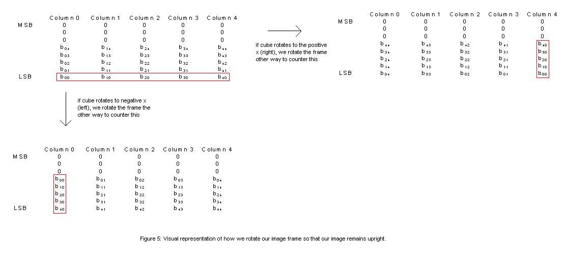
With a little bit fiddling, it is trivial (although slightly tedious) to flip the frame 90 degrees in the appropriate direction.
After all of this, the only thing left to do in the display function, is actually turn on the LED's which are indicated as on in the frame buffer. Basically, we use a for loop to walk through the columns one at a time, turning on the appropriate LED's for 200uS and then off again. This strobing of LED's is so fast that it is not perceptible to the human eye (one sequence of strobing takes about 10mS = 25*2*200uS). For each column, we actually turn on the bottom 3 LED's that are indicated as lit and then the top 2. This limits the current draw from our LED power gating transistors (which aren't rated for a current high enough to turn on 5 LED's in series at the current we were putting through each) and also extended our battery life without causing any negative consequence besides perhaps a small loss in brightness (if any). So, given the column that we want to turn on, we first initialize a temporary character with the bottom three bits equal to the current column's bottom three bits. We then set PORTB.0 to the topmost of the three bits (which grounds layer 3 if high) and set the top 2 most significant bits of PORTC with the next two bits. These ports ground layer 2 and 1 respectively. We then set the lower 6 bits of PORTC with the appropriate select value for which column we are currently lighting. If the column is 0 to 23, we can just set the 6th bit of PORTC to 0 and the lower five bits of PORTC to the number of the column since we set up our encoder select hardware and microcontroller lines to address the columns correctly given the number of the column. If, however, the column is the very last one (number 24 or the 25th column) we need to disable the decoders and enable our sixth select line which simply enables the 25th column. We disable the decoders by setting the bottom five bits of PORTC to 11000. This sends a 11 to the master encoder which selects a non-existent decoder, making all the decoders that gate power to the other columns disabled. Finally, we now have the appropriate bottom 3 LED's lit and we delay 200uS to allow the LED to light up and light to be perceived by viewers eyes, and then we disable the layers and columns by setting all of the grounding lines low, disabling the power line for the 25th and setting the decoder lines to 11000 which again disables all of the lines enabled by the decoders. We then do the top 2 LED's in the column in the exact same fashion except that we enable those layers instead using their appropriate lines on PORTC.
The cube was able to display messages and images with no apparent flicker or delay. Despite lighting a maximum of 3 LED's at a time we were still able to produce images requiring more than 3 LED's to be lit by strobing through multiple LED's at a high rate. The structure was also surprisingly rigid and could withstand mild shaking and turning. This was originally a concern since the entire cube is held together by solder, copper wires, and foam board.
However, the LED's weren't as bright as we had hoped and in a well lit room or on a very sunny day it can be difficult to see what the cube is trying to display. This problem could be fixed in the future by using different transistors that are rated for higher current and by using a smaller resistor. A transistor that is able to supply current to all 5 LED's at the same time would allow you to hold each set of LED's on for longer (increased duty cycle) and a smaller resistor would increase the current through the LED; both of these would contribute positively to the perceived brightness of the LED. Also, given more time we would have liked to come up with a more complicated application of the cube, possibly using it to model fluid dynamics or maybe making it into a 3D pong game.
Our final product was both usable and safe. The cube is battery powered and all the necessary components are contained within the base so the device is both portable and safe. The cube also produces minimal interference with other projects since the only thing that we really 'emit' is red light.
For our project demo, we programmed an introductory string that scrolls across the cube from right to left which reads "ECE476 FINAL PROJECT DEMO" and a short animation which follows the string. The animation consists of some alternating horizontal planes which then change into a horizontal plane at the mid plane of the cube. This then morphs into a horizontal line from the front middle of the cube to the back middle. This morphs into a vertical plane in the center of the cube which then expands into the whole cube being lit. Finally, the LEDs spiral off from the first column in the back left to the very middle column (column 12). A video of this can be seen below along with an example of the orientation changing capability of the cube.
MP4 video -- higher res MOV video
We used this as a demo to show several things. First of all, the scrolling text showed that it was capable to display readable text on a 3D LED cube with the low resolution of 5x5 on a side. This is important for any display. Next, the scrolling text was a good way to show that orientation changes were in fact correct and differentiated turning the cube on the two different sides. The text always scrolls in the correct direction. Next, the animations were a way to show the capabilities of the display. It showed just a small subset of what can be displayed on the cube (anything that can be displayed in a 5x5x5 grid of pixels) including all LEDs turned on, planes, and lines. We can also turn on individual LEDs which is not shown in the demo. It is clear that this is possible based on the lighting scheme. The demo shows both horizontal and vertical planes. Vertical planes are entire columns enabled but horizontal planes are individual LEDs turned on in a single column (strobed one at a time). Since these animations were not back to front symmetric like the text, it also showed that the orientation switching was in fact working correctly (flipping all pixels to the correct positions) when the cube was turned on its side.
Our cube performed reasonably well; we were able to display a message on the cube that was readable if the room was relatively dark and you were looking at it on axis. Our light show also worked as expected and both the message and the light show adjusted themselves when you turned to cube sideways. If we were to redo our project we would have designed a slightly different LED driver circuit that would be able to supply enough current to power all 5 LED's at once and also make each LED brighter. We might also consider making some sort of plexiglass case to make the structure stronger and more visually pleasing. Additionally we would look into displaying some other interesting thing on our cube.
Intellectual Property Considerations
Our cube builds on an idea originally created and patented by James Clar (www.JamesClar.com ) USPTO patent # 7190328. Additionally, our cube is being used only for educational purposes and we have no intent of profiting from James Clar's original design in any way.
Ethical Considerations
Throughout the project we adhered to the IEEE Code of Ethics at all times. We have consistently made decisions that ensured the health and safety of the public and those around us and accept responsibility for these decisions. We also avoided conflicts of interest throughout the project but if we had encountered them we would have disclosed them to all the parties involved. Additionally we have been realistic and honest in reporting the results of our project and have supported our claims and estimations with the appropriate figures and images. While working on our project we did not encounter any form of bribery but if we had we would have promptly rejected it. We have also strived to improve the understanding of the technologies used and their potential applications and have shared our knowledge with the public in the form of this website. We also ensured that our actions would not cause harm or injury to others in anyway by making sure that our circuits were safe and that we turned power supplies off while unattended and did not leave wires exposed in a way that could harm someone.
More importantly we have actively sought criticism of our work from the TA’s and from Professor Land and have corrected errors that they have pointed out. We have also tried our best to assist our peers in their own projects and shared any knowledge we had with those interested. In doing all that we mentioned above we believe we have followed the IEEE Codes of Ethics in its entirety.
#include <Mega32.h>     //includes instruction library for the ATMega32 MCU

  #include <delay.h>      //includes instruction library for time delays/pauses


//Flash array to store how to make characters on our cube (3x5)

//Each character is 3 bytes - first column, second column, third column

flash unsigned char letters[78] = {

 //A

 0b00001111,

 0b00010100,

 0b00001111,

 //B

 0b00011111,

 0b00010101,

 0b00001111,

 //C

 0b00011111,

 0b00010001,

 0b00010001,

 //D

 0b00011111,

 0b00010001,

 0b00001111,

 //E

 0b00011111,

 0b00010101,

 0b00010101,

 //F

 0b00011111,

 0b00010100,

 0b00010100,

 //G

 0b00011111,

 0b00010011,

 0b00011011,

 //H

 0b00011111,

 0b00000100,

 0b00011111,

 //I

 0b00010001,

 0b00011111,

 0b00010001,

 //J

 0b00010001,

 0b00011111,

 0b00010000,

 //K

 0b00011111,

 0b00000100,

 0b00011011,

 //L

 0b00011111,

 0b00000001,

 0b00000001,

 //M

 0b00011111,

 0b00001000,

 0b00011111,

 //N

 0b00011111,

 0b00001110,

 0b00011111,

 //O

 0b00011111,

 0b00010001,

 0b00011111,

 //P

 0b00011111,

 0b00010100,

 0b00011100,

 //Q

 0b00011111,

 0b00010011,

 0b00011111,

 //R

 0b00011111,

 0b00010110,

 0b00011101,

 //S

 0b00011101,

 0b00010101,

 0b00010111,

 //T

 0b00010000,

 0b00011111,

 0b00010000,

 //U

 0b00011111,

 0b00000001,

 0b00011111,

 //V

 0b00011110,

 0b00000001,

 0b00011110,

 //W

 0b00011111,

 0b00000010,

 0b00011111,

 //X

 0b00011011,

 0b00000100,

 0b00011011,

 //Y

 0b00011000,

 0b00000111,

 0b00011000,

 //Z

 0b00011001,

 0b00010101,

 0b00010011

};


//Flash array to store how to make numbers on our cube (3x5)

//Each character is 3 bytes - first column, second column, third column

flash unsigned char numbers[30] = {

 //0

 0b00011111,

 0b00010001,

 0b00011111,

 //1

 0b00010001,

 0b00011111,

 0b00000001,

 //2

 0b00010011,

 0b00010101,

 0b00011101,

 //3

 0b00010101,

 0b00010101,

 0b00011111,

 //4

 0b00011100,

 0b00000100,

 0b00011111,

 //5

 0b00011101,

 0b00010101,

 0b00010111,

 //6

 0b00011111,

 0b00010101,

 0b00010111,

 //7

 0b00010001,

 0b00010010,

 0b00011100,

 //8

 0b00011111,

 0b00010101,

 0b00011111,

 //9

 0b00011101,

 0b00010101,

 0b00011111

};


//Current frame info, and acceleration data

float a_x, a_y;                    //Current converted accelerations

float bias_a_x, bias_a_y;          //Calculated biases of x and y axis accelerometers

unsigned char data_ready;          //Flag indicating acceleration conversions ready

unsigned char intro_pos;           //Current position in the introduction string (scrolled)

unsigned char intro_string[133];   //Buffer to hold all columns representing intro string

unsigned char cur_frame[25];       //Buffer for current frame (25 columns - each bytes

                                  //5 least significant bits represent the five LEDs in a

                                  //column which are on if bit is 1, and off if bit is 0

unsigned char temp_convert[25];    //Buffer for a frame to use as temporary storage


//Animation states

#define INTRO_STRING                   0

#define ALTERNATING_HORIZONTAL_PLANES  1

#define PLANE_TRANSITION               2

#define CENTER_LINE_TO_VERTICAL_PLANE  3

#define VERTICAL_PLANE_TO_ALL          4

#define ALL_TO_NONE                    5

unsigned char animation_state;                             //Current animation state

unsigned char animation_count;                             //Count variable for use with

                                                          //animation updating

unsigned char animation_temp;                              //Another useful variable to use

                                                          //when animating, temporary state

unsigned char plane_sequence[4] = {0x11,0x0a,0x04,0x0a};   //Sequence of column values for use

                                                          //in the alternating planes animation

unsigned char temp_frame[25];                              //Temporary frame buffer to keep frame

                                                          //state between animation updates


//A/D Conversion

#define IDLE         0

#define CONVERTING_X 1

#define CONVERTING_Y 2

unsigned char conversion_stage;  //Conversion state variable

unsigned char ADC_accel_x;       //Reading from the ADC converter for X acceleration

unsigned char ADC_accel_y;       //Reading from the ADC converter for Y acceleration


//Temp variables (made global for faster allocation in method)

unsigned char i, temp;

unsigned int count;


//Scheduling timer variables

#define DISPLAY_TIME 16

unsigned char display_count;       //Scheduling variable for display task

                                  //Scheduled at ~ 60Hz (62.5Hz)


//Method prototypes

void display_task(void);           //Display task

void initialize(void);             //Initialization routine

void calibrate_sensors(void);      //Sensor calibration routine

void init_intro(flash char* str);  //Intro string initialization - takes a string and

                                  //converts it to column values for display


/**

 * Timer interrupt code running at 1000 Hz (ms tick).

 **/

interrupt [TIM0_COMP] disp_int(void)

{

 //Decrement display count each millisecond (used to schedule display task)

 if (display_count > 0) display_count--;

}


/**

 * ADC done interrupt, allows us to do one conversion after the other (accel_x,accel_y)

 **/

interrupt [ADC_INT] adc_int(void)

{

 if (conversion_stage == CONVERTING_Y)

 {

   ADC_accel_y = ADCH;               //Grab the converted value of Y_Accel

   conversion_stage = CONVERTING_X;  //Update conversion stage

   ADMUX |= 0x01;                    //Switch conversion channel to A1 (x-accel)

   ADCSR &= 0xef;                    //Clear interrupt flag (just to be safe)

   ADCSR |= 0x40;                    //Start a new conversion

 }

 else if (conversion_stage == CONVERTING_X)

 {

   ADC_accel_x = ADCH;               //Grab the converted value of X_Accel

   conversion_stage = IDLE;          //Update conversion stage

   ADMUX &= 0xf8;                    //Clear conversion channel back to A0 (y-accel)

   ADCSR &= 0xef;                    //Clear interrupt flag (just to be safe)

   data_ready = 1;                   //Now we have both converted values, data is ready

 }

}


/**

 * Main loop.

 **/

void main(void)

{


 initialize();


 //Main loop

 while(1)

 {

   //Schedule tasks

   if (display_count == 0) display_task();

 }


}


/**

 * All the functionality is in this display task.  It keeps animation/demo state and fills in

 * a frame buffer with the current LEDs to be lit in this frame (this is called once every 16mS

 * for a refresh rate of about 62.5Hz).  The method also grabs acceleration values if they are

 * ready from the conversion task (which converts both x and y acceration channels and then sets

 * a flag) and then checks whether the acceration values are near +- gravity whose values were

 * found with experimentation.  If so, we flip the frame on its side left or right to keep the

 * same orientation of the frame with respect to the ground.

 **/

void display_task(void)

{

 display_count = DISPLAY_TIME;  //Reschedule this task


 //We are displaying the demo opening string

 if (animation_state == INTRO_STRING)

 {

   //Render appropriate frame right side up (current 5 columns for all

   //rows) offset by our current position in this prerendered string

   for (i = 0; i < 5; i++)

   {

     cur_frame[i]    = intro_string[intro_pos+i];

     cur_frame[i+5]  = intro_string[intro_pos+i];

     cur_frame[i+10] = intro_string[intro_pos+i];

     cur_frame[i+15] = intro_string[intro_pos+i];

     cur_frame[i+20] = intro_string[intro_pos+i];

   }


   count++;  //Use count to slow update (12*16mS = 192mS between scrolling updates)

   if (count > 12)

   {

     count = 0;

     intro_pos += 1;


     //If we are at the end of the string, set animation_temp with its next value and

     //switch to first animation state "ALTERNATING_HORIZONTAL_PLANES"

     if (intro_pos > 128)

     {

       animation_temp = 0x11;

       animation_state = ALTERNATING_HORIZONTAL_PLANES;

     }

   }

 }

 //We are displaying two horizontal planes moving up and down opposite each other

 else if (animation_state == ALTERNATING_HORIZONTAL_PLANES)

 {

   //Render frame right side up (all columns get same value)

   for (i = 0; i < 25; i++)

   {

     cur_frame[i] = animation_temp;

   }


   count++;  //Count slows update (again 192mS between updates)

   if (count > 12)

   {

     count = 0;

     animation_count++;  //Use this count to clock through the animation sequence

     animation_temp = plane_sequence[animation_count & 0x03];


     //Once we have done the animation a few times (and get to just a middle plane)

     if (animation_count == 0x1f)

     {

       animation_temp = 0;

       animation_count = 0;

       animation_state = PLANE_TRANSITION;

     }

   }

 }

 else if (animation_state == PLANE_TRANSITION) //Horizontal plane to front to back (middle) line

 {

   //Render frame right side up

   //First clear the frame

   for (i = 0; i < 25; i++)

   {

     cur_frame[i] = 0x00;

   }

   //Then turn on the appropriate middle LEDs (out *animation_count* turned off)

   for (i = animation_temp; i < 5-animation_temp; i++)

   {

     cur_frame[i]    = 0x04;

     cur_frame[i+5]  = 0x04;

     cur_frame[i+10] = 0x04;

     cur_frame[i+15] = 0x04;

     cur_frame[i+20] = 0x04;

   }


   count++;  //Count slows update (192mS between updates)

   if (count > 12)

   {

     count = 0;

     animation_count++;  //Clock through animation sequence


     //Once the plane has turned to front to back line, switch animation states

     //Want to then turn front to back line into a vertical plane on the middle

     //LEDs from front to back

     if (animation_count == 3)

     {

       animation_temp = 0x04;  //First value for the plane

       animation_count = 0;

       animation_state = CENTER_LINE_TO_VERTICAL_PLANE;

     }

     else

     {

       animation_temp = animation_count;

     }

   }

 }

 else if (animation_state == CENTER_LINE_TO_VERTICAL_PLANE)  //Front to back line to vertical plane

 {

   //Render frame right side up

   for (i = 0; i < 25; i++)

   {

     cur_frame[i] = 0x00;

   }

   cur_frame[2] = animation_temp;

   cur_frame[7] = animation_temp;

   cur_frame[12] = animation_temp;

   cur_frame[17] = animation_temp;

   cur_frame[22] = animation_temp;


   count++;  //Count slows update (192mS between updates)

   if (count > 12)

   {

     count = 0;

     animation_count++;  //Clock through animation sequence


     //Update the next value to use for the center columns

     switch (animation_count)

     {

       case 1 : animation_temp = 0x0e;

                break;

       case 2 : animation_temp = 0x1f;

                break;

       case 3 : animation_temp = 2;

                animation_count = 0;

                animation_state = VERTICAL_PLANE_TO_ALL;  //Next animation state

                break;

     }

   }

 }

 else if (animation_state == VERTICAL_PLANE_TO_ALL)  //Transition from vertical plane to all lit

 {

   //Render frame right side up

   for (i = 0; i < 25; i++)

   {

     cur_frame[i] = 0x00;

   }

   //Turn all LEDs on for all columns front to back for inner 1+2*animation_temp LEDs

   for (i = animation_temp; i < 5-animation_temp; i++)

   {

     cur_frame[i]    = 0x1f;

     cur_frame[i+5]  = 0x1f;

     cur_frame[i+10] = 0x1f;

     cur_frame[i+15] = 0x1f;

     cur_frame[i+20] = 0x1f;

   }


   count++;  //Count slows update (15*16mS = 240mS between updates)

   if (count > 15)

   {

     count = 0;

     animation_count++;  //Clock through the animation (set animation_temp

                         //appropriately for next display frame)

     switch (animation_count)

     {

       case 1 : animation_temp = 1;

                break;

       case 2 : animation_temp = 0;

                break;

       case 3 : animation_temp = 0;

                animation_count = 0;

                animation_state = ALL_TO_NONE;

                //Initialize the temporary frame with the current one (all on)

                for (i = 0; i < 25; i++) temp_frame[i] = cur_frame[i];

                break;

     }

   }

 }

 else if (animation_state == ALL_TO_NONE)  //Spiral to none lit

 {

   //Render frame right side up

   for (i = 0; i < 25; i++) cur_frame[i] = temp_frame[i];


   count++;  //Count slows update (192mS between updates)

   if (count > 12)

   {

     count = 0;

     animation_count++;  //Clock animation


     //This is the update seqence for the all lit cube spiralling inwards to

     //none, turning off columns as we spiral, given the following column

     //orientation looking at the cube from above:

     // 0  1  2  3  4

     // 5  6  7  8  9

     // 10 11 12 13 14

     // 15 16 17 18 19

     // 20 21 22 23 24

     //The sequence of columns to turn off is:

     // {0,1,2,3,4,9,14,19,24,23,22,21,20,15,10,5,6,7,8,13,18,17,16,11,12}


     //First 5 we count from 0

     if (animation_count < 6)

     {

       temp_frame[animation_count-1] = 0x00;

     }

     //Next four we count by fives from 9 (simplified below)

     else if (animation_count < 10)

     {

       temp_frame[animation_count*5 - 21] = 0x00;

     }

     //Next four we count down by ones from 23

     else if (animation_count < 14)

     {

       temp_frame[33-animation_count] = 0x00;

     }

     //Next 3 we count down by fives from 15

     else if (animation_count < 17)

     {

       temp_frame[(17-animation_count)*5] = 0x00;

     }

     //Next 3 we count up by ones from 6

     else if (animation_count < 20)

     {

       temp_frame[animation_count - 11] = 0x00;

     }

     //Next 2 we count up by fives from 13

     else if (animation_count < 22)

     {

       temp_frame[(animation_count - 20) * 5 + 13] = 0x00;

     }

     //Next 2 we count down by ones from 17

     else if (animation_count < 24)

     {

       temp_frame[39 - animation_count] = 0x00;

     }

     //For the final two we count up by ones from 11

     else

     {

       temp_frame[animation_count - 13] = 0x00;

     }


     //Once we have gone through all the columns, go to next state

     if (animation_count == 25)

     {

       animation_temp = 0;

       animation_count = 0;

       animation_state = INTRO_STRING;  //Back to intro string

       intro_pos = 0;                   //Make sure we are at first position

     }

   }

 }


 //If conversion data is ready, clear flag, get accelerations, start next conversion

 if (data_ready)

 {

   data_ready = 0;  //Clear data ready bit


   //Convert the sampled 8-bit values to accelerations +/- 74/g (x) and 77/g (y)

   a_x = -((float)ADC_accel_x - bias_a_x);

   a_y = -((float)ADC_accel_y - bias_a_y);


   //Start a new conversion

   conversion_stage = CONVERTING_Y;

   ADCSR |= 0x40;

 }


 //Now flip frame sideways as necessary


 if (a_x > 65.0) //We are on +x side, scroll up, come up with frame

 {

   //Convert this frame to left is bottom (zero bits of all become last column, etc)

   //First columns bit is first bit etc


   for (i = 0; i < 5; i++)

   {

     temp = 5*i;


     //Last column (all first bits in order)

     temp_convert[temp+4] = (cur_frame[temp+0] & 0x01) | ((cur_frame[temp+1] << 1) & 0x02) |

                            ((cur_frame[temp+2] << 2) & 0x04) | ((cur_frame[temp+3] << 3) & 0x08) |

                            ((cur_frame[temp+4] << 4) & 0x10);

     //Second to last column (all second bits in order)

     temp_convert[temp+3] = ((cur_frame[temp+0] >> 1) & 0x01)  | (((cur_frame[temp+1] >> 1) << 1) & 0x02) |

                            (((cur_frame[temp+2] >> 1) <<  2) & 0x04) | (((cur_frame[temp+3] >> 1) << 3) &  0x08) |

                            (((cur_frame[temp+4] >> 1) << 4) & 0x10);

     //...

     temp_convert[temp+2] = ((cur_frame[temp+0] >> 2) & 0x01)  | (((cur_frame[temp+1] >> 2) << 1) & 0x02) |

                            (((cur_frame[temp+2] >> 2) <<  2) & 0x04) | (((cur_frame[temp+3] >> 2) << 3) &  0x08) |

                            (((cur_frame[temp+4] >> 2) << 4) & 0x10);

     //...

     temp_convert[temp+1] = ((cur_frame[temp+0] >> 3) & 0x01)  | (((cur_frame[temp+1] >> 3) << 1) & 0x02) |

                            (((cur_frame[temp+2] >> 3) <<  2) & 0x04) | (((cur_frame[temp+3] >> 3) << 3) &  0x08) |

                            (((cur_frame[temp+4] >> 3) << 4) & 0x10);

     //First column (all fifth bits in order)

     temp_convert[temp+0] = ((cur_frame[temp+0] >> 4) & 0x01)  | (((cur_frame[temp+1] >> 4) << 1) & 0x02) |

                            (((cur_frame[temp+2] >> 4) <<  2) & 0x04) | (((cur_frame[temp+3] >> 4) << 3) &  0x08) |

                            (((cur_frame[temp+4] >> 4) << 4) & 0x10);

   }


   //Replace frame

   for (i = 0; i < 25; i++)

   {

     cur_frame[i] = temp_convert[i];

   }

 }

 else if (a_x < -65.0) //We are on -x side, scroll down come up with frame

 {

   //Convert this frame to left is top (zero bits of all become first column, etc)

   //Last columns bit is first bit etc


   for (i = 0; i < 5; i++)

   {

     temp = 5*i;


     //First column (all first bits in reverse order)

     temp_convert[temp+0] = (cur_frame[temp+4] & 0x01) | ((cur_frame[temp+3] << 1) & 0x02) |

                            ((cur_frame[temp+2] << 2) & 0x04) | ((cur_frame[temp+1] << 3) & 0x08) |

                            ((cur_frame[temp+0] << 4) & 0x10);

     //Second column (all second bits in reverse order)

     temp_convert[temp+1] = ((cur_frame[temp+4] >> 1) & 0x01)  | (((cur_frame[temp+3] >> 1) << 1) & 0x02) |

                            (((cur_frame[temp+2] >> 1) <<  2) & 0x04) | (((cur_frame[temp+1] >> 1) << 3) &  0x08) |

                            (((cur_frame[temp+0] >> 1) << 4) & 0x10);

     //...

     temp_convert[temp+2] = ((cur_frame[temp+4] >> 2) & 0x01)  | (((cur_frame[temp+3] >> 2) << 1) & 0x02) |

                            (((cur_frame[temp+2] >> 2) <<  2) & 0x04) | (((cur_frame[temp+1] >> 2) << 3) &  0x08) |

                            (((cur_frame[temp+0] >> 2) << 4) & 0x10);

     //...

     temp_convert[temp+3] = ((cur_frame[temp+4] >> 3) & 0x01)  | (((cur_frame[temp+3] >> 3) << 1) & 0x02) |

                            (((cur_frame[temp+2] >> 3) <<  2) & 0x04) | (((cur_frame[temp+1] >> 3) << 3) &  0x08) |

                            (((cur_frame[temp+0] >> 3) << 4) & 0x10);

     //Fifth column (all fifth bits in reverse order)

     temp_convert[temp+4] = ((cur_frame[temp+4] >> 4) & 0x01)  | (((cur_frame[temp+3] >> 4) << 1) & 0x02) |

                            (((cur_frame[temp+2] >> 4) <<  2) & 0x04) | (((cur_frame[temp+1] >> 4) << 3) &  0x08) |

                            (((cur_frame[temp+0] >> 4) << 4) & 0x10);

   }


   //Replace frame

   for (i = 0; i < 25; i++)

   {

     cur_frame[i] = temp_convert[i];

   }

 }


 //Render the frame


 //Go through each column turning on appropriate lights of current frame (strobe)

 for (i = 0; i < 25; i++)

 {

   //Do the bottom 3 layers

   temp = 0x00;

   if (cur_frame[i] & 0x01)

   {

     temp |= 0x01;

   }

   if (cur_frame[i] & 0x02)

   {

     temp |= 0x02;

   }

   if (cur_frame[i] & 0x04)

   {

     temp |= 0x04;

   }


   PORTB = temp >> 2;


   if (i < 24)

   {

     PORTC = i | (temp << 6);

   }

   else

   {

     PORTC = 0x38 | (temp << 6);

   }


   delay_us(200);  //Delay for 200uS to allow light to hit eyes


   //Disable the columns

   PORTC = PINC & 0xdf;

   PORTC = PINC | 0x18;


   //Disable the grounding (make grounding controls 1)

   PORTC = PINC & 0x3f;

   PORTB = PINB & 0x00;


   //Do the top 2 layers

   temp = 0x00;

   if (cur_frame[i] & 0x08)

   {

     temp |= 0x08;

   }

   if (cur_frame[i] & 0x10)

   {

     temp |= 0x10;

   }


   PORTB = temp >> 2;


   if (i < 24)

   {

     PORTC = i | (temp << 6);

   }

   else

   {

     PORTC = 0x38 | (temp << 6);

   }


   delay_us(200);  //Delay for 200uS to allow light to hit eyes


   //Disable the columns

   PORTC = PINC & 0xdf;

   PORTC = PINC | 0x18;


   //Disable the grounding (make grounding controls 1)

   PORTC = PINC & 0x3f;

   PORTB = PINB & 0x00;

 }

}


/**

 * Initialize the microcontroller.

 **/

void initialize(void)

{

 // LED Cube Control Ports


 // DDRC.0 = Decoder control bit 0 (LSB)

 // DDRC.1 = Decoder control bit 1

 // DDRC.2 = Decoder control bit 2

 // DDRC.3 = Decoder control bit 3

 // DDRC.4 = Decoder control bit 4 (MSB)

 // DDRC.5 = 25th column

 // DDRC.6 = Bit 0 of led ground

 // DDRC.7 = Bit 1 of led ground


 // DDRB.0 = Bit 2 of led ground

 // DDRB.1 = Bit 3 of led ground

 // DDRB.2 = Bit 4 of led ground


 DDRB = 0x07;

 DDRC = 0xff;


 PORTB = 0x00;

 PORTC = 0x18;


 //set up timer 0

 TIMSK=2;              //turn on timer 0 cmp match ISR

 OCR0 = 249;           //set the compare re to 250 time ticks

 //prescalar to 64 and turn on clear-on-match

 TCCR0=0b00001011;


 //Set up scheduling variables

 display_count = DISPLAY_TIME;


 //Set up current state

 data_ready = 0;


 //init the A to D converter (maybe do 10-bit and low noise stuff if necessary)

 //channel zero/ left adj /INTERNAL Aref

 ADMUX = 0b11100000;

 //enable ADC and set prescaler to 1/128*16MHz=125,000 (may want this faster)

 //and clear interupt enable

 ADCSR = 0b10001111;


 //Do calibration of ADC

 calibrate_sensors();


 //Initialize the landscape with strings

 init_intro("    ECE476 FINAL PROJECT DEMO    ");  //Must be less than 33 chars in length

 count = 0;

 intro_pos = 0;


 animation_state = INTRO_STRING;


 #asm

   sei

 #endasm


 //Start a new conversion

 conversion_stage = CONVERTING_X;

 ADCSR |= 0x40;

}


/**

 * Calibrate the sensors (simply find the initial zeros of the two accelerometers

 * by averaging over three readings).  We assume that the cube is started in the

 * right side up state and not on its side although this may partially work for

 * if it is started on its side as well.

 **/

void calibrate_sensors(void)

{

 ADMUX &= 0xf8; //MUX to channel 0 (y-axis)

 ADCSR |= 0x40; //Start conversion

 while (!(ADCSR & 0x10));

 ADCSR &= 0xef; //Clear interrupt flag


 bias_a_y = (float)ADCH;


 ADCSR |= 0x40; //Start conversion

 while (!(ADCSR & 0x10));

 ADCSR &= 0xef; //Clear interrupt flag


 bias_a_y += (float)ADCH;


 ADCSR |= 0x40; //Start conversion

 while (!(ADCSR & 0x10));

 ADCSR &= 0xef; //Clear interrupt flag


 bias_a_y += (float)ADCH;

 bias_a_y /= 3;


 ADMUX |= 0x01; //MUX to channel 1 (x-axis)

 ADCSR |= 0x40; //Start conversion

 while (!(ADCSR & 0x10));

 ADCSR &= 0xef; //Clear interrupt flag


 bias_a_x = (float)ADCH;


 ADCSR |= 0x40; //Start conversion

 while (!(ADCSR & 0x10));

 ADCSR &= 0xef; //Clear interrupt flag


 bias_a_x += (float)ADCH;


 ADCSR |= 0x40; //Start conversion

 while (!(ADCSR & 0x10));

 ADCSR &= 0xef; //Clear interrupt flag


 bias_a_x += (float)ADCH;

 bias_a_x /= 3;


 ADMUX &= 0xf8; //Reset MUX channel back to 0

}


/**

 * Initialize an array of columns to be displayed given a flash

 * string to display at the start.

 **/

void init_intro(flash char* str)

{

 unsigned char index;


 //Initialize the string to all zero (off)

 for (i = 0; i < 133; i++)

 {

   intro_string[i] = 0x00;

 }


 //For each character in the string, look up the representation in our

 //flash table and set the columns appropriately

 for (i = 0; i < 33; i++)

 {

   if (str[i] >= 'A' && str[i] <= 'Z')

   {

     index = 3 * (str[i] - 'A');  //Offset into representation array for letters

     intro_string[i*4+1] = letters[index];

     intro_string[i*4+2] = letters[index+1];

     intro_string[i*4+3] = letters[index+2];

   }

   else if (str[i] >= '0' && str[i] <= '9')

   {

     index = 3 * (str[i] - '0');  //Offset into representation array for numbers

     intro_string[i*4+1] = numbers[index];

     intro_string[i*4+2] = numbers[index+1];

     intro_string[i*4+3] = numbers[index+2];

   }

 }

}
| Part | Quantity | Price |
|---|---|---|
| Mega32 Prototype Board | 1 | $5.00 |
| Mega32 Socket | 1 | $0.50 |
| 74LS04 Hex Inverter | 6 | $3.42 |
| CD74HCT238 3-8 Decoders | 4 | Sampled |
| SOIC Breakout Board | 4 | $4.00 |
| Red LED (LEDTECH UT1841R-81) | 125 | $5.00 |
| Freescale Battery Clip 3/5 Volt Regulator | 1 | Sampled |
| Freescale MMA6261Q Accelerometer Board | 1 | Sampled |
| LM340T5 1A 5V Regulator | 1 | $1.66 |
| Large Protoboard | 1 | $2.50 |
| Medium Protoboard | 1 | $1.00 |
| zvp3306a Transistor | 25 | $5.95 |
| zvn3306a Transistor | 5 | $1.45 |
| Header machine pins | 100 | $5.00 |
| Atmel Mega32 Microcontroller | 1 | $8.00 |
| Foam Board | 1 | $6.00 |
| 9V Battery | 1 | $2.00 |
| Thick guage wire | 3 Rolls | Free (Pre-owned) |
| Various Resistors, Capacitors, and Wire | - | Free (Lab) |
| Total | $51.48 |
Thank you to Texas Intruments, Freescale Semiconductor, and Maxim Integrated Products for their generous samples.
Similar Project (Inspiration)
LED Cube Construction Tutorial (Inspiration and guidance)
74LS04 Hex Inverter Chip
CD74HCT238 3-8 Decoder
MMA6261Q Accelerometer
Atmel Mega32
LM340T5 5V Regulator
ZVP3306A P Channel MOSFET
ZVN3306A N Channel MOSFET
Red LED UT1841R-81