
ECE 476 Spring 2008 Final Project
Rebecca Slovak (ras94@cornell.edu)
Matt Meister (mrm58@cornell.edu)
Elias Bermudez (deb48@cornell.edu)
Introduction and High Level Design
Our project was to design a two degree-of-freedom stationary helicopter, autonomously controlled by an evolving neural network. A normal helicopter has six degrees of freedom, which makes any form of control exceptionally hard, let alone autonomous control. What our design does is limit the movement of our system to just two degrees-of-freedom, up and down, and side to side which lets it rotate around the center, while at all times keeping the system rigid in the other four degrees-of-freedom.
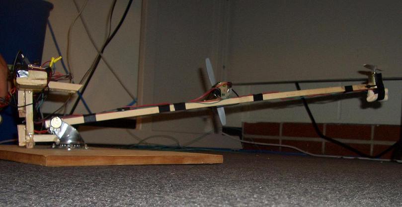
The Helicopter in Flight!
Our final project was not our original goal. The evolution of our project design was an adventure in itself. Originally, we planned to design a triangular helicopter. The concept was to put the microcontroller in the center of a triangular structure, and attach motors at each of the three points. The motors would all have propeller blades attached to them, and would spin at the same speed, creating lift, and raising the helicopter. The structure would move in any of the three directions by lowering the speed of the motor at that corner, causing that point to dip downwards, and letting the other two motors propel the device forwards. Movement in each of the three directions would be controlled manually by pressing buttons on a remote-control. After analyzing the mechanical issues of this design, and speaking to a few professors, we decided to change our plan. We were told that there would be problems with unbalanced torque, which would cause the whole ! structure to spin, and would make our control system much more complicated than we had expected.
With this information, we decided to design a quad-copter instead, which would consist of two sets of counter-rotating propellers. We hoped this would eliminate the issue of unbalanced torque in the system, and still let movement be possible by lowering the speed of two motors simultaneously. Controlling motion this way would cause one side of the system to dip, creating the unbalanced lifting forces that cause motion, but still keeping the torques balanced. Unfortunately, after talking to various Professors and analyzing the control scheme that would be required to keep the system stable, we again reached the conclusion that this project was too much for us in this timeframe. We would not have enough time to implement a sufficient control scheme, and our budget was not large enough to allow us to purchase four sets of motors and propeller blades that would be strong yet light enough to create sufficient lift, while still also allowing us money for other c! omponents like the microcontroller itself and various sensors.
After changing our ideas twice, we talked with Professor Land about the feasibility of our ideas, and what we could do instead. We still hoped to design something that could fly. After some brainstorming, we came up with what became our final idea: the two degree-of-freedom learning helicopter, controlled by an evolutionary neural network. Restricting the movement of the helicopter by attaching it to an arm eliminates the need to stabilize a true hovering device, making the hardware much simpler, and the neural network learns how to best control itself, thereby replacing the need for a traditional PID controller.
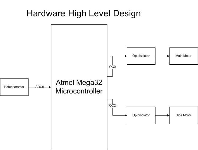
Block Diagram of Hardware High Level Design
Hardware
The hardware aspect of this project was a mix of mechanical construction and electrical components. In the structure aspect, we needed a large and stable base, but also a light yet strong arm to support our motors. On the electrical side, the hardware was very similar to that which was used in Lab 5.
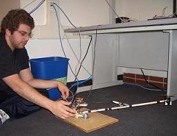
Matt working on the helicopter
First and foremost, we needed to find a strong, yet affordable motor and propeller blade combination. This is actually the main reason that our original ideas were deemed not feasible for this project. After consulting two professors in the Mechanical and Aerospace Engineering Department, it was determined that motors that were strong and light would not be cheap enough for the budget constraints we had, since we would have required three motors for our first idea, and four for our second idea. Once we switched to the armed structure, however, we had more leeway in the weight and cost aspects of our motors. After researching how RC helicopters work and testing various motors and propeller blades from destroyed toys, we were referred to a group which did a similar project in 2004. Their project was a stationary, one degree-of-freedom helicopter that was controlled by a classical PID controller. What was of more interest to us, however, was their physical setup. They achieved their goal by using a standard DC motor from RadioShack with a simple, 2 blade propeller attached directly to the motor shaft. This was considerably simpler than the systems we had thought of implementing, which would have required a gearing system to provide greater torque to the propeller. Based on the success of their project 4 years ago, we decided to use the same motor and propeller blade setup. We purchased similar motors from RadioShack and ordered the propeller blades online from HobbyLobby.com.
We then had to figure out the physical construction of the system. We needed a base large enough to hold our components, and heavy enough to remain in place while the helicopter ran, and we needed a setup which would allow the system to have to have two degrees-of-freedom. The base was simple enough - we used a large piece of scrap wood provided to us by Professor Land. Creating the rotating arm required some creative thought. After coming up with the idea of attaching some kind of hinge joint to a rotating disk, we went to Lowes to purchase the necessary parts. While there, we spoke to an Lowes employee and received some help as to how to go about doing our construction. He pointed us to a rotating caster which actually took care of both the hinge and the rotation. A rotating caster is what is generally used to hold each wheel on the bottoms of swivel-chairs, or other wheeled equipment. We removed the wheel from the caster, and the remaining structure was perfect for our project. From here, we just had to screw the caster onto the base, and add the arm.
Next, we had to start playing around with different combinations of wood, motors, and propeller blades in order to find the best configuration for the structure. The most critical part was having a sturdy arm that would survive a large amount of testing and would not buckle under the weight of the motor attachet to the end. At first, we tried using some scrap maple that was provided to us by Professor Land. Unfortunately, even though this wood was very sturdy, it proved to be much too heavy; the motor could not lift itself and the arm together. We then went back to Lowes to search for lighter wood. Lowes provided us with several peices of scrap wood free of charge. Unfortunately, this wood also was not a success. The scrap wood from Lowes proved to be both too wide for the caster, and still too heavy for the motor to lift. It was at this point that we went to the Cornell Store on campus and purchased a long stick of bass wood. This wood is very light, like balsa wood, but still has enough stiffness to provide a stable arm. The only issue was that the piece was very thin, and would slide back and forth from one side of the caster to the other. We fixed this by cutting off two small pieces and gluing them to either side of where the arm connected to the caster. This made the width perfect, and we moved on to working on the actual joint structure.
We knew that the arm had to be able to swing freely around the joint in the caster, but we also needed a way of determining the angle that the arm was at relative to ground. Our initial thoughts were to attach an accelerometer to the arm and simply to use the metal shaft that comes with the caster to provide a joint to swing around. We worked with the accelerometer until one of the TAs suggested we try using a potentiometer in the joint, since the accelerometer did not seem to have the speed and accuracy we required. After some initial testing with a potentiometer we found in the lab, we ordered some of our own to use in the joint. This method turned out to be perfect for our needs, as we were able squeeze the potentiometer knob into the wood so that as the arm rose, it would twist the potentiometer knob with it. We used two potentiometers to connect the arm to the caster, so as to keep the design symmetric and well-balanced, but we only used one for our data input. The other remained unconnected.
At this point, all that remained in the physical structure was to actually secure the motors. We did this by gluing the motors to the wood, and then securing them further using cable ties. This was to ensure that the motors would not be able to move during operation. One of the TAs then pointed out that all our wires would get tangled up when the structure spun around the caster. We realized that we needed to mount the electrical hardwareso that it would rotate with the arm. We took care of this by using some of the scrap wood from Lowes that we had not used. We cut it down to fit into the caster and stick up behind it in a T-shape. The stand structure is connected to the sides of the caster, and is secured by massive amounts of hot glue. The electrical components are mounted on top of it.
As mentioned earlier, the electrical hardware was very similar to the hardware created for Lab 5, which was a Digital Thermometer with a fan. The part of interest to us was the fan side of the hardware, since the fan used in that lab was essentially a DC motor, and functioned similarly to the motors we planned to use for this project. The motors, like the fan in Lab 5, required optoisolator circuits to protect the microcontroller circuit from the high-voltage power supply. This was especially important since each motor runs on a 19V supply, and pulls 1.6A of current when running, and the microcontroller must be protected from any back-EMF generated by the motor while it switches on and off. To provide power to the motors, we used Matt's 19V laptop power supply. We constructed two optoisolator circuits, like the ones from Lab 5, on small solder boards and mounted them to each end of our hardware stand. The schematic for these circuits, as well as the pin outs for the various components of the circuits, can be seen in Appendix 2. The only notable change we made to the original Lab 5 circuit shown in this schematic, was to completely disconnect the base connection of the BJT in the optoisolator chip (Pin 6) from the rest of the circuit. This essentially creates infinite resistance for the resistor that does not have a value marked in the schematic
We also constructed a Protoboard with the Mega32 microcontroller. To do this, we followed the schematic provided on the ECE 476 Lab 6 page, and used the components provided in the lab. We mounted this circuit in the center of the hardware stand. The schematic for this board can be seen in Appendix 2.
We drilled several small holes along the length of the wooden arm which allowed us to snake wires along the arm and to the motors from both the protoboard and the optoisolator circuits without tangling wires together.
The other main aspect of the electrical hardware was in connecting the potentiometer to the microcontroller. The component is essentially a variable resistor. The output voltage varies with the resistance. The two ends of the potentiometer are connected to ground and Vdd respectively, and the output is connected to the ADC input on the microcontroller.
Software
The software presented a challenge because none of us had any previous experience working with neural networks or evolutionary software. We spoke to a grad student who recommended a book, Neural Network Design by Hagan, Demuth, and Beale. The book provided us with a general understanding of neural networks, but it was not specific enough to give us an idea of how to begin coding.
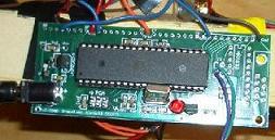
A closeup view of the protoboard at the base of the helicopter
On last years ECE 476 project page, we found that Joanna Dai and David Drew programmed a neural network controlled robot, which learned to avoid collisions. David recommended that we read the paper, Evolutionary BitsnSpikes by Dario Floreano, Nicolas Schoeni, Gilles Caprari, and Jesper Blynel. This paper taught us specifically about spiking neural networks, and how exactly they work. David told us that this type of neural network worked well for their robot, and would likely be successful for our helicopter as well. We contacted Dario Floreano, the author of the paper, to receive permission to implement his algorithm, and he replied, granting us permission. We also spoke to David and Joanna, and they gave us permission to study their code, and use it to write ours.
A spiking neural network is designed to function as a brain, and the terminology associated with the artificial neural network is based off of the biological terminology associated with the brain. Its structure is essentially that of a simplified brain: it consists of neurons with many connections between them. The input to the neural network comes from external sensors. The sensor must be connected to at least one neuron, and may be connected to many or all of them. When the sensor is at certain values (predetermined in the code) it sends a pattern of spikes into the network. It does this in the code by turning on certain bits for each neuron it is connected to. The other neurons in the network can also send out spikes. Each neuron has a membrane potential associated with it. When a neuron receives a spike from a sensor or another neuron, its membrane potential increases. Each neuron has a randomly determined threshold for the membrane potential. Whe! n the potential passes this value, the neuron sends out a spike to the other neurons to which it is connected. Certain neurons in the network are set to be the output neurons. These neurons are the only ones that directly control the hardware. When these neurons pass their potential, they cause something to happen in hardware.
When the network is initialized, it creates a number of individuals. An individual is a single instantiation of the network with random connections. Each individual consists of the entire set of neurons, including the output neurons, with random connections. The connections from the sensors to the neurons are random, as well as the connections between the neurons. When the program runs, one individual is randomly chosen and mutated. The program then runs on the network of that particular individual for a set amount of time and calculates a fitness value. The fitness of an individual is determined by how well the hardware performed (the task that it is learning to do) while running on the individuals network. A fitness value is stored for each individual. Whenever a mutated individual runs with a fitness which is better than the worst currently stored value, that individual is saved, and the worst one is discarded. Over time, the program will evolve! to contain only individuals with high fitness, so eventually, every trial will be a good one.
Our implementation of this neural network is a very small system. We used only one sensor: the potentiometer which measured how high the propeller had risen. The sensor input to the network was the result of the A to D conversion of the potentiometer value. We used eight neurons in our network, two of which were output neurons. One output neuron is designated the up neuron and its job is to raise the speed of the motor. Similarly, the other output neuron is the down neuron.
When our network is initialized and the first set of individuals is created, we set the sensor to be connected to every neuron (this is to ensure that each starting network is in one connected piece, and not fragmented), and the neurons have random connections between each other. When the program runs, one of the individuals (we create ten total) is chosen and mutated. The fitness is calculated based on the current potentiometer value. When the potentiometer is below a certain value (which we called floor because below this value, the helicopter is resting on the floor, or very close to doing so), the fitness does not go up. In this state, the sensor sends a pattern of many spikes into the network. We want it to send many spikes, because when the helicopter is very far off from the goal, many spikes will cause it to change more quickly. When the helicopter is above the floor value, but below the goal range, the fitness is increased in increments of o! ne, and a smaller number of spikes are sent into the network. We increase the fitness here because it is a good place for the helicopter to be: it can hover safely here, but it is still below the goal range. When the helicopter is within the goal range, we increase the fitness in increments of two. If the helicopter stays in this range for a long time, its fitness will grow very large. This is the ideal place for the helicopter to hover, so we do not send any spikes into the network in this case. When the helicopter is in a range that is above the goal range but below a value we call limit, we send a small number of spikes into the network but do not increase the fitness. We do not increase the fitness here because while the helicopter could be stable hovering below the goal range, when it passes the goal range, it has a tendency to rise higher and higher and reach its top value. The motor was more responsive to going up than to going down, so we decided it would b! e best not to increase the fitness at all above the goal range. Above the value called limit, we do not increase the fitness, and we send a pattern of many spikes into the network. This pattern is different than the pattern sent when the helicopter is too low. The system will evolve to understand what the patterns of spikes mean, and will eventually configure its connections in a way that causes spikes to reach the up-output when the helicopter needs to go up, and to reach the down-output when the helicopter needs to go down.
Each mutated individual is run for a set number of cycles, which takes approximately one minute each. The fitness of the individual is calculated and compared against the other fitness values. If the current mutated individual surpasses the previous worst individual, it overwrites the worst individual. This system can run indefinitely and continually evolve. Each time an individual finishes running, the motor slows down, and the helicopter settles to the floor as it starts the next individual. We wanted our helicopter to eventually evolve to hover forever, so we added a statement that says if the fitness is very high, and the helicopter is in the goal range, it should not slow down the motor, but rather it should start running the next individual at the same motor speed. Once the helicopter has many good individuals, it evolves to this condition.
The code is broken into several tasks which are controlled by a task-scheduler in main:
Task 1 runs the fastest and occurs many times during each individual. The motor spike counters are reset, the membrane potentials are recalculated, and the neuron spikes and motor spikes are generated. There is also a leakage constant subtracted from the membrane potentials if they go above a certain value so they do not increase too fast.
Task 2 also runs many times during each individual, but not as fast as task 1. This task modifies OCR0, which controls the motor. It increases it if the up motor spike counter is greater than zero, and decreases if the down motor spike counter is greater than zero. (motor spikes are calculated in task 1)
Task 3 runs faster than task 2, but slower than task 1. This task reads the potentiometer value from the A to D converter. It sends a pattern of spikes into the network based on which range the potentiometer is in, and it calculates the fitness. When we experimented with the side motor, we also did that in this task. When the fitness was high enough and the motor was in the goal range, we turned on the side motor. We decided to eliminate the side motor though, because it propelled the device around very fast which could be dangerous, and it also caused the power wires to tangle.
Task 4 runs once per individual. It determines which fitness is worst out of the population of ten individuals, and compares the fitness of the current individual to it. Whichever individual is worse is discarded. This task also chooses the next individual to mutate, and randomly mutates it. The membrane of this individual is reset to zero. The motor speed (OCR0) is set back to its reset value, or if the fitness is high enough and the helicopter is in the goal range, the speed instead remains at its current value.
Task 5 runs only once every few minutes. It logs all important variables to eeprom so that if the chip is reset, values are not lost. This task sets a flag that tells the chip how to initialize. If it is 0, then the chip is being programmed for the first time, and initialized in the normal way. If it is 1, then the program initializes with the stored values from eeprom. The best fitness values are also stored in a very large array. Each time this task runs, the current best fitness is stored. The array is large enough that we could run the program for several hours, storing a value every few minutes, and not fill up the array. When our chip is connected to hyperterm through an STK500, the best fitness values print out to hyperterm.
Results
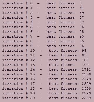
Figure 2.
Our design was able to evolve and perform very well in under an hour. Figure 2 shows the best fitness values logged to hyperterm over the course of one evolution. The values in this chart are the fitnesses of the best individual in the set of ten each time the data is logged to hyperterm.
It is clear from this data that the fitness improves over time. The value that it reaches is near the highest fitness value possible. The system never found an individual with a better fitness. This is still success though, because perfect fitness is not much higher. The rest of the chart is not shown because it shows the same value for many more iterations over the course of the hour that the program was run.
It looks as though the system does not improve after iteration 15, but actually it does: at iteration 15, there was most likely only one individual with near perfect fitness. After many more iterations, nearly all individuals did as well. We could see this simply by watching the helicopter: over time, it left the goal range less and less often, and eventually, rarely left the goal range at all.
Conclusion
All three of us would agree that in the end, this was a very successful project. Although the neural network concept was challenging, and we had many bugs to work out in both hardware and software, we are proud of our end result. Watching our helicopter start out barely able to lift off the ground, and then watching it slowly evolve and improve was very satisfying.
Intellectual Property Considerations
For intellectual property considerations, we sought permission from Professor David Floreano to use his algorithm for our system. A transcript of his permission can be seen below. We also sought permission and help from David Drew and Joanna Dai, who did a similar project last year.

Copy of Email from Professor David Floreano
David and Joanna had already recommended that we add noise to the thresholds to prevent locked oscillations. We do this in task one.
Ethical and Legal Considerations
The main issue we really had to deal with in our ethical considerations was making sure we had proper permission to implement the algorithm that was the basis of our project. This algorithm was the subject of a paper written by Professor David Floreano in 2002, so we emailed him for permission to use his methods. He gave us full permission, and even some tips on how to avoid possible problems. Aside from the intellectual property issues, there is also a potential issue in safety. Our project is meant to be more of a proof-of-concept rather than a usable toy or demo. Our implementation makes use of propeller blades spinning at very high speeds, and is therefore potentially dangerous. Although the system itself is stable and secure, if a user came to close and was not careful, they could potentially get hurt, though not seriously. In fact, one of our friends purposely stuck his finger into the propeller when it was running at full speed. He was actually in more ! danger from our anger than from the propeller itself. Aside from potential injury, we comply with the rest of the IEEE Code of Ethics. We did not take any form of bribery, we cited the sources we used, and were not discriminatory in how our project can be used. Furthermore, we received and incorporated constant help and critique from both our peers and instructors.
Acknowledgements
First and foremost, we would like to thank Professor Land for teaching such a fantastic class. The three of us agree that while we have been presented with many challenges, we have learned tons and have had lots of fun. We would also like to thank the dedicated staff of TAs for being such a great source of information, critique, and random conversation to help pass the LONG hours spent in the lab. We would also like to thank all of our classmates for putting up with our testing, as the system is not exactly what one would call quiet.
Additionally, we would like to extend a large thank you to Alvin Haley of Avnet for providing us with four sampled Mega32s. Even though we only asked for one, he provided us with three extras in case anything went wrong.
Appendix
Appendix 1.
Appendix 2.
Schematics
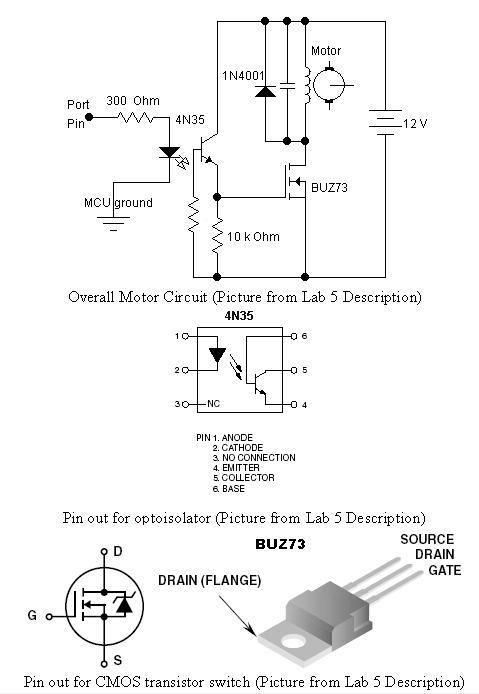
Schematic for Optoisolator Circuit
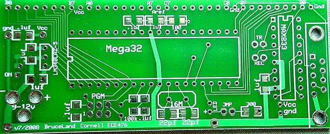
Schematic for Prototype Board (by Professor Land, from ECE 476 website)
Appendix 3.
Budget
| Item | Cost per Item | Number of Items | Total Cost |
|---|---|---|---|
| $29.36 | |||
| Potentiometers | $0.50 | 2 | $1.00 |
| Motors | $3.99 | 2 | $7.98 |
| Small Solder Boards | $1.00 | 2 | $2.00 |
| Custom PC Board | $5.00 | 1 | $5.00 |
| Swivel Caster | $4.38 | 1 | $4.38 |
| Propeller Blades | $3.20 | 2 | $6.40 |
| Headers for Optoisolator | $0.05 | 6 | $0.30 |
| Headers for Pin Connectors | $0.05 | 16 | $0.80 |
| Wood Arm | $1.50 | 1 | $1.50 |
| Circuit Components (resistors, etc.) | Provided by the Lab | -- | -- |
| Laptop Power Supply | Owned by Matt | 1 | -- |
| Mega32 MCU | Sampled from Avnet | 1 | -- |
| Wood Base | Provided by Professor Land | 1 | -- |
| Wood for Hardware Stand | Sampled from Lowes | 1 | -- |
Appendix 4.
Task Breakdown
Matt Most hardware, construction, testing and debugging
Elias Software, testing and debugging
Rebecca Software, some hardware, website, testing and debugging
Appendix 5.
References
-
Professor David Floreanos 2002 Paper Evolutionary BitsnSpikes
(http://www.alife.org/alife8/proceedings/sub4681.pdf) -
David Drew and Joanna Dais Evolving Neural Robot
(http://instruct1.cit.cornell.edu/courses/ee476/FinalProjects/s2007/jxd2/djd36_jxd2/neuralrobot.htm)
And their program
(http://instruct1.cit.cornell.edu/courses/ee476/FinalProjects/s2007/jxd2/djd36_jxd2/robot.c) -
Stationary Helicopter (2004 Project by Tom Ling and Norbert Huber)
(http://ltc.cit.cornell.edu/courses/ee476/FinalProjects/s2004/tl92/tl92_nh48_476finalproj/index.htm) -
ECE 476 Lab 5
(http://instruct1.cit.cornell.edu/courses/ee476/labs/s2008/lab5.html) -
Atmel Mega32 Supplier, Avnet
(http://avnet.com) -
Propeller Vendor, Hobby Lobby
(http://HobbyLobby.com) -
Potentiometer Vendor, AllElectronics
(http://AllElectronics.com) -
ECE 476 Main Page
(http://instruct1.cit.cornell.edu/courses/ee476/)