|
I. Introduction This project simulates 9 holes of a minigolf course using the TV to display the course (top down view), an anchored plastic ball containing two accelerometers, and a putter. Summary We used a hollow plastic ball containing two accelerometers for each planar axis with the ground, and anchored it to an object above it so it would swing in a pendulum motion when hit, eventually settling back into the same position it started out with. The accelerometers were hooked up to the ADC converter on the prototype board and interpreted with a single Mega32. A different Mega32 would be used to control video output, displaying a top down view of the current course the user was playing, along with a ball. The Mega32 programmed with the ADC converter would constantly communicate with the video Mega32. The ADC converter would detect drastic changes in the voltage output from the accelerometers, and use that output to determine the speed at which the ball will travel from its resting location. A stronger putt will result in a greater acceleration, resulting in a greater output from the accelerometer, which translates to a faster moving ball on screen. The magnitude of the accelerometers will also determine the direction in which the user hit the ball, creating a velocity vector using the readings from the two. We chose to do this project because we wanted design some sort of video game using the microcontroller. After discussion, we felt that this particular project integrated a good bit of software design with some hardware design - the combination we wanted. II. High Level Design Our idea came from a brainstorm session, but the initial concept was to use lasers in sequence that would detect the velocity and direction of the swing. This would allow driving and other higher power swings that might otherwise damage or destroy a set of accelerometers. However, due to the unanticipated high cost of lasers and sensors, the idea was eventually scrapped in favor of limiting the game to mini-golf, which doesn't require as powerful of swings, so that we could use the accelerometers instead. The math behind this was fairly simple, using the concept that a force is an acceleration, which translates to a velocity. Other math involved included collision physics for the ball colliding with the course walls. Our courses consisted of horizontal, vertical, and perfectly 45 degree diagonal walls. This would result in collisions where the x or y velocity vectors would be reversed (with vertical and horizontal walls) or the x and y velocity vectors would be reversed and switched (with diagonal walls). However, the accelerometers only reacted to changes in its alignment in a certain direction. We tethered the ball containing the accelerometers to a string so movement in a direction would give it a pendulum motion in which the internal accelerometers' alignment would change. We then oriented the two accelerometers in two different directions so one accelerometer would react to changes in alignment in one direction while the other in the other direction. When the program starts, the first course is displayed on the screen to the user. The program waits for the user to strike the ball. This is monitored by the Mega32 on the protoboard. The inputs are sent over the ports to the STK 500 Mega32 and the velocity of the ball is computed. The user is then showed the ball moving on the screen until drag forces stop it. The total number of shots are displayed on the screen and is incremented each time the user shoots. When the ball stops moving, the user can shoot again. Once the ball moves over the cup, the user moves on to the next hole. The hole is displayed on the screen and the procedure repeats. Once the user completes the last level, it shows the user's score and the current low score. The user is told if they have the all-time low score on the course. III. Program/Hardware Design Program Details For the ADC converter, we had to design the program so that it would alternate between the two accelerometers on each read. The program would then constantly take two running averages of the previous ten values that were read from each accelerometer. Once there was a value read that was greater or less than a certain threshold from the average, then the program would go into "hit" mode and begin recording either the min or the max value that the accelerometer achieves and gather the reading from the other accelerometer at that point. The program will continue to do this until the accelerometer returns to close to the previous resting average value. Up until this point the ADC polling program was constantly outputting the resting averages through a port for each accelerometer, which would be read by the other Mega32 that was writing video code to the TV. Once "hit" mode is completed and the max or min value has been gathered, the program will then output these gathered values through those same ports (C from protoboard to C on STK500 and D from protoboard to A on STK500). The other Mega32 is rendering video to the TV. It is rendering a top-down view of the putt-putt courses featured in the game, as well as a pixel representing the golf ball's position in the course. This program is also reading in the accelerometer values from the other Mega32. Once it detects a great change in the readings, which is when the other program will start outputting its gathered reading due to a hit, it will take these values and convert them to velocity vectors. This will in turn affect the ball on screen, moving it in the direction of the velocity vectors. There is also a drag factor that affects the velocity, slowing the ball down over time. For collisions, when the ball's next (x,y) position coincides with a colored pixel, which would be part of a wall, then the program looks for pixels around the collision pixel. This corresponds to a vertical (pixels directly above and below), a horizontal (left and right), or diagonal (offset above and below). The program will then change the velocity accordingly. Once the velocity of the ball goes back to zero due to drag forces, than this Mega32 will output a signal to the other Mega32 signaling it is ready for another hit. The other Mega32 will then begin gathering a running average for the resting value again and wait for another drastic change in the accelerometer readings, signaling another hit. Now that the ball can be moved based upon hardware input, it must interact with the course. The course is composed of horizontal, vertical, and 45 degree lines. The code checks the current pixel location of the ball and its surrounding 8 pixel neighbors. For instance, when the ball intersects a horizontal line, the western and eastern pixels relative to the current ball location will also be colored in by the line. This works well for horizontal and vertical lines, but diagonal lines turned out to be difficult. That is one reason we decided to do only 45 degree lines. There are only a few cases that we need to check with 45 degree lines. We handle the intersections of lines on a course by course basis. We found this to be the easiest way to deal with the few corner cases that arose on each level. Hardware Details We used an STK500 and a protoboard each mounted with a Mega32, along with several connectors to connect ports together so the Mega32's can communicate with each other. We used two accelerometers (Freescale - part no. MMA1260D) and mounted them inside two hollow plastic hemispheres which we then glued together to form a ball. We then ran wires out of the ball connected to the vital pins in each accelerometer and connected them to the protoboard that housed the Mega32 that would be used for ADC. The other Mega32 used Port D and a set of resistors to output a signal to the television to render the courses and the ball. We originally tried to keep the ADC and the video rendering on the same Mega32, but that meant that we could only gather values from the accelerometer through the ADC at the framerate that the video code was outputting to the screen (or else tearing would occur). This proved to be too slow to reliably read values from the accelerometer, so we opted to use another Mega32 to purely read values from the ADC as fast as it can switch between the two accelerometers. Discarded Ideas We had many different ideas on how to input the swing from the user. As was mentioned earlier in this document, we were going to try to use lasers to time the velocity of the swing and its angle. However, after ordering a couple laser diodes and examining how we wanted to get the project to work, this idea had to be thrown out because of cost. These parts still contribute almost $15 to our overall total cost that we are not using. A second idea was to use pressure sensors on either end of the club head to determine how hard each side of the club was struck. In this manner, we thought we could determine the relative angle at which the ball should move and its velocity fairly well. However, we did not have the correct pressure sensors in lab, and these would also have been costly to order. This led us to use the Freescale accelerometers donated to the lab to sense the motion of the ball. As stated before, two 1-axis accelerometers still do not provide us with great accuracy. Borrowed Code / Ideas Video code used in this lab was based upon code provided by Professor Bruce Land in this document. The code to output to the screen and interact with output that has been placed in the buffer to the screen are his. Also, he designed the character sets that output to the screen. Our code uses this base to output our courses and text / data to the screen. IV. Results of the Design The time from physically hitting the ball to the results of the hit being displayed on screen through the movement of the ball is fast, with very little delay. The rendering itself also shows no artifacting on the screen, even for the more complex courses, because those courses are rendered piecewise on different frames until the full course is rendered on screen. The game also records how many hits it took for the user to get the ball into the hole for each course, and also keeps a running total score that is displayed at the end of the 9th or final hole. The two Mega32's seem to work fine concurrently. They are controlled by signals passed between them to allow each to know what data to transmit. Unfortunately, since we had to cobble together two single-axis accelerometers to look at two different axes, we feel we did not achieve the same accuracy that one would get with a single two-axis accelerometer. While straight hits in either x or y direction register fine, diagonal hits are more of an issue and are somewhat inconsistent. Also, the fixed point arithmetic causes inconsistencies occasionally. This game is very usable by anyone with with a basic understanding of how mini-golf works, and playable by anyone who can hold a putter. The safety of the game is reliant on how the user operates the putter. The actual hardware design and game itself is not responsible if the user wields the putter in an unsafe manner. As far as we are aware, this project did not interfere with anyone else's project. It does not transmit wireless signals. V. Conclusions Our design met our expectations reasonably. However, because the accelerometers could only handle up to 1.5 G's, we had to scrap our original idea of having both a driving simulation and a mini-golf game and focus purely on the mini-golf. We would have been also better off purchasing a two-axis accelerometer instead of using two single-axis accelerometers. Our design also went through many revisions before settling on the use of the accelerometers, so there was some budget and time wasted on these other initial designs before the final one. If we were to do this project again, we would still use basically the same code for outputting courses; however, we would try to use a two-axis accelerometer or other better means of receiving user input. Our code uses our own system of sending signals back and forth between Mega32's; therefore, we did not have to adhere to any standards. The only code we re-used was the video code provided in Lab 4 for the ECE476 course. The link to this code was provided above in the design and credited as well to Professor Bruce Land. We did not use any other code except the video code and the code we wrote in the last few weeks on this project. We created our own design and did not reverse engineer any idea already created. The only sample parts we used were already provided to the instructor by the respective companies, thus we did not deal with any vendor ourselves. IEEE Code of Ethics Our mini-golf simulator is completely environmentally friendly and safe when the game is played as intended and the putter is used correctly. We never intended for the game to have a malicious purpose, and the purpose of the game is to just provide entertainment and perhaps even improve a user's skills at real mini-golf. Besides the video code which was provided in a previous lab, all other code in our programs was written by us. We did seek help with all our previous designs, and opted for the accelerometer design when we received opinions that our previous designs would not work as we thought. However, besides the basic idea that accelerometers should factor into our design, all the finer details of the hardware design was developed and created by us. We also credit the others in the class who we occasionally sought help from in lab in how to use the hardware we were using. We also brainstormed ideas for some of the more difficult or underdeveloped aspects of the hardware design with others in the class. However, the decisions on which hardware to use and how to design and program them was ultimately up to us, as it was our project. We linked to a Youtube clip from the cartoon "The Simpsons" on the main page of this website. This is the only legal consideration we must account for as it is copyrighted by Twentieth Century Fox (however this version is from Germany and may not be copyrighted, thus it still appears on YouTube). Appendix A: Commented Program Listing Our video code can be found here. Our ADC code can be found here. Appendix B: Schematics Accelerometer 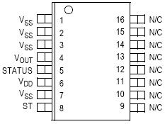 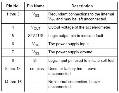 Diagram for the Printed Circuit Board containing accelerometer that is mounted inside the ball: 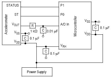 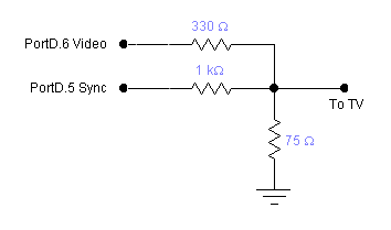 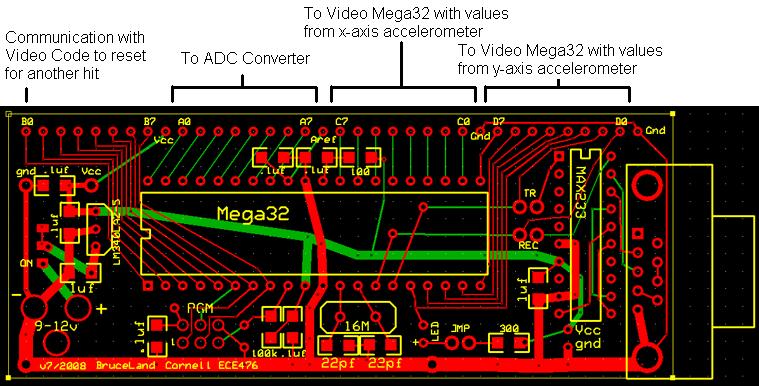 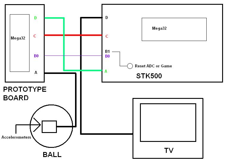 Appendix C: Budget / Parts/ Data Sheets Accelerometers Manufacturer: Freescale Semiconductor Part Number: MMA1260D Quantity: 2 Cost: $0 Programmable Hardware Manufacturer: Atmel Corporation Part Number: ATmega32 Quantity: 2 Cost: $8 x 2 Manufacturer: Atmel Corporation Part Number: AVR® STK500 Quantity: 1 Cost: $15 x 1 Prototype Board for ADC Converter Quantity: 1 Cost: $5 x 1 Video Manufacturer: Jensen Part Number: J53-BWR Quantity: 1 Cost: $5 x 1 Breadboards White board Quantity: 1 Cost: $6 x 1 Small solder board Quantity: 1 Cost: $1 x 1 Cables and Connectors 2-pin flat jumper cable Quantity: 1 Cost: $1 x 1 DIP socket Quantity: 1 Cost: $.50 x 1 SIP or Header socket/plug Quantity:8 Cost: $.05 x 8 Laser Diodes Manufacturer: Lumex Opto/Components Inc Part Number: OED-LDP65001E Quantity: 2 Cost: $5.37 x 2 Photocells Manufacturer: Advanced Photonix Inc Part Number: PDV-P9006 Quantity: 2 Cost: $1.77 x 2 Golf Clubs Putter of unknown make and model with a Peak Performance Series shaft. Not included in budget because it was already in our possession. Total Budget: $64.18 Appendix D: Specific Tasks Both partners: EVERYTHING. Most tasks were undertaken in tandem, and problems were worked through together. The code was written up by both partners, without specific sections tasked out to a single partner. Shane Pryor provided the golf clubs. Appendix E: References Datasheets ATmega32 AVR® STK500 MMA1260D OED-LDP65001E PDV-P9006 Vendor Sites DigiKey Code References Video Code: ECE 4760 Lab 4 Video Code (Lunar Lander) Written by Bruce Land |