

Introduction
The main idea for our project was to implement an inexpensive solution to the current CU Snake Arm motor-driving system by using a Mega644 microcontroller instead of multiple 3-Amp motor controllers as the snake arm was originally intended to be driven. Since we used DC motors, we implemented a PID control algorithm that determines the speed of the motors using PWM to achieve the best accuracy possible.
The motors can be controlled with Hyperterm or a Wiimote. Hyperterm allows for numerical input of each motor's position ranging from 0 to 255. The Wiimote sends IR data via Bluetooth to a MacBook, which then sends the information to the MCU through a serial connection.
High Level Design
Rationale and Motivation
The Snake Arm team at Cornell designed its fourth generation arm having multiple cells involving gear assemblies, chains, springs, strings and pulleys. In order to move the arm accurately to a desired position, a real-time feedback is required.
The feedback is provided using potentiometers coupled with the motors through gears and shafts. The Snake arm team initially planned on using one Polulu 3-A motor controller to drive each DC motor. The fact that each Pololu PID controller can drive only one motor and has a cost of $50 imposes an inherent limitation in terms of cost and utility as the complete snake arm would require at least 10 controllers (5 segments). In this project, we implement a multiple PID motor controller using the Atmel Mega644 microcontroller which can drive up to 8 motors. This saves enormous cost and pain of calibration for the team.
We have also implemented Wii remote interface with our motor controller. This gives the snakearm more intuitive wireless flexibility in terms of motion control.
Background Math
The main feature of the motor controller is the ability to use feedback from sensors to continually update the motor operation and minimize error using the PID algorithm. The error is the difference between the desired condition set by the user through one of the input modes, and the actual condition reported back by a sensor. In our case the sensor is a potentiometer coupled with the motor shaft through a gear assembly and pulley system.
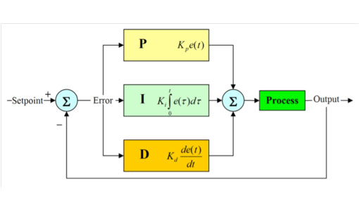
Block diagram showing components of the PID mechanism.
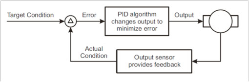
Diagram illustrating the concept of the PID algorithm.
Tuning Method
We used manual tuning. We first set the Ki and Kd values to zero and kept on increasing the Kp until we reached a suitable value. After having full load on the motor we increased Kd until the motors were able to move the entire segment to the extreme points. Finally we increased Ki until the loop worked within an acceptable error range High values of Kd lead to extreme motor motion and instability. Increasing the Integral term helped us to get rid of oscillation problems.
Logical Structure

Overall flow of the project.
The user can send instructions (Final Positions of the Snake arm segment) either by using Hyperterminal or by moving the Wii remote in the desired direction. The instruction is then sent to the protoboard, which generates required PWMs.
The motors move according to the PWMs while also turning the coupled potentiometers. The voltage signal from the potentiometer is fed back into the MCU ADC as the feedback. The H-bridges are used for direction control and the opto-isolator circuits for MCU protection. There are three signals going through separate opto-isolators into the H-bridge: the PWM, the brake (activated when desired position is reached), and the direction bit.
Hardware/Software Tradeoffs
A big tradeoff we faced was using the printf statement. Due to the large number of cycles introduced by the printf statement, we started losing pulses in the PWM. This led us to disable displaying of real time values of the ADC input on Hyperterm. We overcame this constraint by enabling the 8 LED's on the STK board. We read the ADC input in binary by observing these LED's. It fitted our need as the values on our potentiometer ranged from 0-255, all of which can be covered using 8 bits.
We opted against hardware PWM signals and had to implement manual PWMs because we wanted to allow for future expansion by setting the algorithm up to work with as many motors as there are pins available. This enables us to drive up to eight motors using the same microcontroller. As a result, the PWM signals we manually generate aren't as fast as those from the timers in PWM mode, but they are fast enough for our DC motor driving purposes.
Hardware Design
Mechanical Components
Each segment of the snake arm comprises of three cells and two DC motors. The two motors are used to give the segment four degrees of freedom. One of the motor controls movement in the left-right direction while the other controls it in the up-down direction.
The red circular disks are three inch in diameter, laser-cut, out off acrylic for reduced weight. The motor frame has been CNC milled from Aluminum. Ball bearings are used to reduce friction. The gear assembly establishes a 20:1 worm gear reduction ratio. This leads to a maximum pulling force of 100 lbs per cable. The gap between each circular disk is 2 inches and each disk can rotate up to 20 degrees. Fiber rope is used for motion which allows the cable to be in tension at the center position thus reducing the dead zone at the straight ahead position. Opposite cables act in pairs, pull in cable on the inside of the curve, let out cable on the outside of the curve, chain and sprockets are used to synch the opposing pulleys. Springs have been attached for giving rigidity and support to the segment.
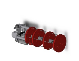
Figure showing single segment with gear assembly attached at the back end. The red circular disks are made out of acrylic and form the main body of the segment.
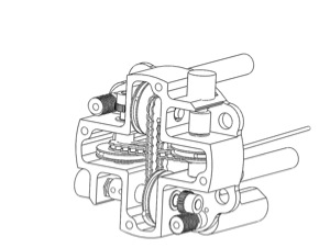
Close up sketch of the gear assembly showing the motors, shafts, coupled potentiometers, chains, pulleys and the strings.
Electronic Components
Motor
We used the COPAL 60:1 gear motor, it is a high power, light weight and very efficient motor. The main reason for selecting this motor was the high amount of torque it can provide. The operating range is 6-18volts. We carried out all the tests and calibrations using 12 volts and duty cycles of of 25%, 50% and 100%.
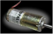
COPAL 60:1 motor
Potentiometer
We used a Bourns single turn 10K potentiometer for getting the feedback signal.
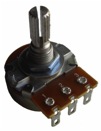
Bourns single turn 10K 3862c
H-Bridge
We used the LMD18200 3A, 55V H Bridge. One H bridge is used to control one motor. Three main signals are being sent into the H Bridge which is the PWM, the brake and the direction bit.
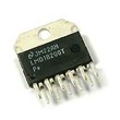
The LMD18200 H- Bridge
Opto-Isolator
We modified the Opto Isolator circuit provided to us by Professor Bruce Land for the Lab exercise number 5. Three opto isolator circuits were required per motor: one for the brake signal, one for PWM, and the other one for direction.
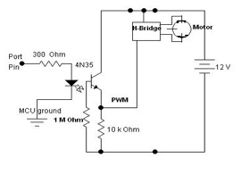
Schematic showing PWM signal being fed into the H-Bridge through the opto-isolator
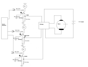
Schematic showing PWM, Brake and Direction signals going through optoisolators to the H-bridge
Wiimote and LEDs
The Nintendo Wii remote has a built in IR camera, which senses IR radiation from our IR LED circuit and calculates the position coordinates using triangulation method. The data from the Wii remote CPU is sent to the computer via Bluetooth. Since we couldn't find enough IR LEDs in the lab, we borrowed a Wii "sensor" (really just ten LEDs hidden in a shiny black box) from a friend.

The Nintendo Wii remote has a built in IR camera which helps in IR based position sensing.
Software Design
Timers and PWM
Since we want to adjust the speed of the motor depending on how far it is to where we want it to be (or how far the measured value is to the reference value), we must use PWM to regulate the voltage the MCU sends to the motor. Because there will be more segments and motors added to the Snake Arm in the future, we chose to implement PWM manually instead of using timers in PWM mode since we would like to control as many motors as there are pins available in the MCU. Thus, the PWM we implemented isn't as fast or as accurate as using timers in PWM mode, but such precision is not necessary to properly control DC motors.
The manual PWM we used was rather simple to implement, with only a few lines of code that will enable adding implementation for more motors in an easy manner. We set a pulse period to 2.5 ms (anything slower than this made the motor's operation jittery since the pulses are too long), and each motor's pulse width is set by the PID algorithm.
We use timer0 in a 100 microsecond timebase for all our operations by setting the compare reset to 200 ticks and the prescalar to divide by 8 (thus, timer 0 compare match ISR overflow occurs every 200 ticks at half a microsecond each). This speed is more than enough to ensure PWM pulses that are fast enough to drive our motors without jitter.
PID - Reading current motor position and getting where we want to go
In order to get feedback from the motors, we read the value from a one-turn potentiometer connected to the motor via a gear assembly. Whenever the motor moves, the potentiometer moves along with it and changes its potential, which we read through Port A in the MCU. We left the ADC readout values from the "default" range of 0 to 255, so each motor has 255 possible positions: 0 being the leftmost in the x-direction motor and down-most in the y-direction motor, and 255 the rightmost and upmost.
We had to carefully schedule each ADC readout from Port A as the MCU can only perform one conversion at a given point in time. For this, we used the ADC ISR, which interrupts every time a conversion is completed. Using flags and setting the value of ADMUX properly, we can get readouts from up to 8 motor/potentiometer combinations.
Every 100 ms, we get the desired motor position values (set by the user through hyperterm or wirelessly from Wii, more on this later) and current motor positions from the potentiometers. These two values are input to our PID algorithm, which returns an "error" value that we use to set each motor's pulse width-the greater the error, the greater the pulse width and thus the faster the speed. As the motor gets closer and closer to where we want it to be, it starts to slow down until it eventually comes to a complete stop. After a few grueling hours of calibration, we found the optimal PID constants that brought our motors to within 3 points of our desired position (out of 255 possible positions): a P of 0.4, I of 0.009, and D of 0.032.
Wii and Hyperterm - Telling the Snake Arm where to go
There are two ways a user can move the robot in our implementation: through hyperterm and Wii. Our main target was the Wii, but we decided to allow controlling the robot through hyperterm too for future usability: sending a string through RS232 starting with "x" or "y" followed by the desired motor position from 0 to 255 drives the motors. Modifying these strings for multiple segments is very easy and will probably be done in the near future for integration with Snake Arm's current motor control GUI.
A more exciting control approach is wirelessly through Wiimote. We followed the same approach as last year's Wiimote Crane project to send the Wiimote's IR coordinates to the microcontroller, but we process these values differently. Communication from the Wiimote to the robot flows as follows:
1) Using a modified version of the DarwiinRemote (version 0.6) application for Mac built with the XCode IDE, the Wiimote calculates its IR coordinates with respect to our IR sensor circuit and sends them to the MacBook wirelessly via Bluetooth. These values range from 0 to 1023 for x, and from 0 to 767 for y. If no signal is detected, both values are set to 1023.
2) The DarwiinRemote tweaks kick in-we modified the WiiRemote Framework (version 0.5) code available online and replaced DarwiinRemote's build with our own to extract the IR coordinates and detect if Button A is pressed. We only consume coordinates when the button is pressed to get precise positions every time and avoid jitter.
3) If Button A is pressed, the modified code opens the serial port using "SerialPortSample.c", code available in the Apple Developers' website. Since we used a usb to serial converter, the port we used in the code was in the form of /dev/cu.usbserial-#####.
4) The modified serial port code puts the IR coordinates in a buffer and sends them through RS232 and the serial UART receive and transmit feature on the MCU.
5) The MCU then processes the strings just as it does with hyperterm input, with an additional step:
6) We map the Wiimote's extracted IR coordinates to desired motor values: the x coordinate is the motor that moves sideways and the y coordinate is the one that moves up and down. We split each orientation in nine possible values (instead of 255) depending on the point the Wiimote is pointing at-this can be modified later if more precision is needed, but we believe this is enough for present purposes.
Modifying both the WiiRemote Framework and serial ports required lots of digging through code we didn't use, but after some time and with the Wii Crane's team help we managed to make it work.
We also tried to have a third robot position input: CU Snake Arm's existing Java GUI, which was designed to work with the Pololu motor controllers we are replacing. Unfortunately, this framework's serial communication method only supported sending integers. Due to our limited time, we couldn't change the current GUI structure for our project, and this task will be done later this year.
Conclusions
Everything worked fine, as desired and as per our expectation. We were able to establish fine control within an error range of 10% in all the four directions of motion. We were able to successfully control the system using the Hyperterm and the Wiimote interface. The motor control was fine. The snake arm electrical engineering team lead assured us that our design was good enough to replace the existing Polulu 3-A motor controllers used by the team.
We faced a compatibility issue in integrating the structure with the existing Snakearm GUI, but we were able to overcome it using hyperterm on their computer.
It should be noted that our total cost for a 2- motor PID controller was $44.50. We worked with the project team and still didn't exceed our budget limit. We saved the team a cost of more than 100% on each motor addition. The actual single motor Pololu 3A controller initially used by snakearm team costs $50.00, thus summing to a cost of $100.00 for two motors.
Results of the design
It took us some time to figure out what the best PID constants for our robot were, but after we figured it out the robot was very precise (within 3 out of 255 levels), and fast (at safe, regulated speeds with no sudden stops or changes in direction).
We used Bluetooth for our Wiimote, but it never caused any interference with other people's designs, including another team using a Wiimote who was sitting next to us while we were both testing for hours. Thus, we don't think this will be a practical issue.
We considered safety when it came to stopping the motors: in our first few approaches, the motors stopped simply when the PWM was low, but voltage was still being input to both terminals of the motor (equivalent voltages for a total drop of 0). The motors stopped moving, but the voltage was still there and, if the motors stood still for too long they might become hot and damage the robot or the user. Thus, we implemented a "brake," which effectively shorts the motor and shuts it off instead of simply stopping it.
We thought every aspect of our design with the intention of making the robot both easy to use and even easier to modify. We decided to implement the Wii for more intuitive control of the robot, allowing the user to decide whether it should move up, left, down, or up instead of giving it an obscure numerical input. Furthermore, even though we are only controlling one segment with two motors now, the framework is laid out to smooth any further expansions of up to 8 motors.
Problems faced during the course of the design
We faced many time consuming and frustrating problems during the process. The chain between one of the pulleys in the gear assembly snapped and broke a night before our demo. The motors burnt twice while calibration. We kept on repeatedly losing small shaft nuts. We wasted one full day trying to work with a faulty 10-turn potentiometer. The printf statement messed our PWM's a lot. The opto-isolator once didn't work. We were able to overcome the problems with the help of Professor Bruce Land, the TA's, Brian Johnson, Aditya Anchuri and our own hit and trial methods. Special thanks to Xi for spending an all-nighter with us in lab!
Intellectual property considerations
The hardware segment of the snake arm was not out own design. But we fabricated parts of the segment. The dimensions of individual structural components were provided by Brian Johnson of the Snake arm Mechanical Engineering Team. We are thankful to Brian for providing us all support in fabrication of the segment and helping us fix it, as the segment broke twice during testing and calibration.
We found no patents for the Wiimote and this project will only be used for the CU snake arm team. The interface code for the Wiimote is open source. We reverse engineered the controls of Wii Remote to extract the position coordinates using its IR sensing mechanism.
Ethical Considerations
The IEEE Code of Ethics was considered when developing this project idea. We generated all motor-driving code on our own.
Legal Considerations
We don't intend to gain profit or commercial interest from this project, thus Legal considerations are not of much concern. Bluetooth doesn't interfere with other devices as it stays around frequencies of 2.4 GHz. We have not used any RF transmitters.
Appendix
Appendix A: Cost Details
| COMPONENT | QUANTITY | COST | TOTAL |
|---|---|---|---|
| Total Cost: | -- | -- | $44.50 |
| H Bridge- LMD18200 | 2 | $12.00 per unit | $24.00 |
| H Bridge Holder | 2 | $1.50 per unit | $3.00 |
| Wiimote | 1 | Borrowed - Free | -- |
| Wiimote IR Sensor | 1 | Borrowed - Free | -- |
| Custom PC Board | 1 | $4.00 per unit | $4.00 |
| Atmel Mega644 | 1 | $8.00 per unit | $8.00 |
| Small solder board | 2 | $1.00 per unit | $2.00 |
| Resistor 330 ohms | 6 | Free - ECE4760 | -- |
| Resistor 10K ohms | 6 | Free - ECE4760 | -- |
| Resistor 1M ohms | 6 | Free - ECE4760 | -- |
| Optoisolator - 4N35 | 6 | Free - ECE4760 | -- |
| Connecting wires | - | Free - ECE4760 | -- |
| Max233CPP | 1 | Free - Sampled from Maxim | -- |
| RS232 connector | 1 | $1.00 per unit | $1.00 |
| Sip or header socket/plug | 40 | $0.05 per unit | $2.00 |
| DIP socket | 1 | $0.50 per unit | $0.50 |
Appendix B: Task Distribution
- PID Controller Programming - Angelica Pando
- PID Tuning - Manan Suri, Angelica Pando
- Code Debugging - Manan Suri, Angelica Pando
- Protoboard - Manan Suri, Angelica Pando
- Isolator Circuits - Angelica Pando, Manan Suri
- Soldering - Manan Suri, Angelica Pando
- Segment Fabrication - Manan Suri, Brian Johnson(Access to CNC, mechanical dimensions etc)
- Wii Remote reverse engineering - Angelica Pando
- Troubleshooting - Angelica Pando, Manan Suri
Appendix C: References
Motor (COPAL HG16-060-AA-00)
Datasheet
H-Bridge (LMD18200)
Datasheet
Opto-Isolator (4N35)
Datasheet
Potentiometer (Bourns 3852A-162-103)
Datasheet
Class Lectures on PID, PWM and Lab 5 by Professor Bruce Land
We got considerable help in setting up the wii remote from a previous year final project titled "Wiimote Crane-spring 2008" by Wanling Yih
Appendix D: Code
Download our WiiFramework code changes!