Haptic Appointment Manager
Abe Cantwell (APC33), Balu Nair (BHN3)
Introduction
The Haptic Appointment Manager manages all of an individual’s appointments, ensuring they arrive on time and in the right location by subtly guiding them throughout the day.
This system uses a GPS receiver and a compass to maintain awareness of its absolute and rotational position. By interfacing with a calendar of time stamped waypoints, this system effectively guides the user to his appointments by vibrating in the direction of the next waypoint.
High level design:
Rationale:
People in general have a fairly poor sense of direction and are easily disoriented. While some people do have some sense of dead reckoning, it is questionably accurate and not present in all individuals. Additionally, since human direction finding is intrinsically tied to landmarks, vision impairment has the potential to seriously disorient an individual and make it extremely difficult for them to navigate from location to location. Though personal navigation systems do exist, primarily in cars or for sporting use, they are at best a crutch for a poor sense of direction. Since they use either visual or aural alerts to convey navigational information, they are inherently disruptive to the user. Additionally, the user is only aware of their navigational status when they are actively paying attention to the device. This is not reasonable for most users most of the time, particularly when the user is performing an intense activity.
Early in the course, Bruce mentioned prior work in haptic systems as providing an almost subconscious sixth sense. We decided that a similar system, providing constant navigational information could potentially create a system which would grant its user a perfect, non-disruptive sense of direction. Also, we noted that people are often late for things, and that coupling a navigation system with a scheduled calendar could be extremely useful. To this end, we designed a portable navigation system which interacts with the user entirely through a non-disruptive, haptic belt.
Our device takes a series of waypoints and vibrates in the direction the user needs to walk to reach their goal.
Logical Structure
This project was designed in an extremely modular manner. Early on, we decided on a list of functions that would be needed to use each hardware device. We also added functions that would be necessary for communications between each of the devices. Each hardware device was interfaced by a set of functions existing in their own file that could operate as a standalone program. These different programs were included as headers into a main program that joined them all together. Essentially, this code organization also reflected how the project flows. Essentially, each device was polled and the data was collected to achieve the result. This design strategy was used to essentially define a communication protocol within our project. This strategy proved very successful, as it allowed us to write and alter the code relating to hardware devices without altering the functionality of the overall project. Additionally, it allowed for incremental design and testing as components could be individually tested. Since the communication functions were defined, we could test components without using the rest of the file. When trouble shooting, we were able to view the output of each section and isolate the problem.
Background Mathematics
This project relied heavily on trigonometry and great globe navigation formulas. The following equation, which we found online returns the initial bearing needed to reach a second latitude and longitude pair. This formula is listed below.
![]()
This formula takes into account the curvature of the earth and the fact that the latitude and longitude are not strictly orthogonal to each other. However, in this context, it is not strictly needed as we are using very small distances.
For the compass, additional mathematics is needed to compute
an angle from the two analog readings. Since the compass essentially outputs a
DC value for both sine and cosine of whatever angle it is at, the angle is
recoverable using arctangent. Since ![]() the angle is
determined by the formula
the angle is
determined by the formula![]() where the voltage1
and voltage2 are the signals from the compass.
where the voltage1
and voltage2 are the signals from the compass.
![]()
Standards
RS232 Standard
We used a RS 232 standard for serial data communication between the GPS receiver and our microcontroller. Since our receiver is communicating directly with the microcontroller the voltage levels are of no concern (0 to 5 volts). Both devices have to be running at the same timing setup. The data is transmitted by first sending out a start bit then the data and finally a stop bit. No new data is transmitted unless there is a new start bit.
NMEA Standard
The data in the NMEA format includes the position, velocity and time sent out by the GPS receiver. Each line of data is a sentence that first contains a prefix that defines the device (GP for GPS receiver) followed by a character sequence that defines the sentence contents. Each sentence begins with a ‘$’ sign. This is followed by the UTC position fix, latitude in degrees/minutes, direction of latitude, longitude in degrees/minutes, direction of longitude, number of Svs, satellite ID number and an end character. The data transmitted is just contained in ASCII format. The NMEA standard for data transmission is 4800 baud.
Motorola Proprietary Binary Standard
The Oncore GPS receiver uses a special proprietary standard to display the information it receives from satellites. The Motorolla Bit Format standard does not follow the standard NMEA format so parsing the data is impossible without knowledge of the standard. After the searching the internet for a couple hours we were able to find information on the Motorolla binary format. The Receiver sends a status message that always begins with the character @@Ea and ends with a carriage return (<CR>) and a line feed (<LF>). The status message contains data regarding Date, UTC time, latitude and longitude position, velocity and a compass heading. The standard baud rate for this message is 9600 baud.
Patent, Copyright and Trademark Concerns
Our project uses a number of patented components as subcomponents. However, there appear to be no patent limitations on our overall design as we are using all of the devices as the manufacturer intended. Also, while both the Motorola proprietary binary standard and NMEA 0183 are described in copyrighted white papers, both standards are widely used and propagated in the minimal form we are using, including a number of open source projects. Our use here is clearly legal.
Hardware/software tradeoff
One of our more difficult tasks was to successfully interface with the compass. We could have avoided this by using a less accurate digital compass from the same company, but we ultimately decided the higher accuracy was worth the additional labor.
Detailed Design
Hardware
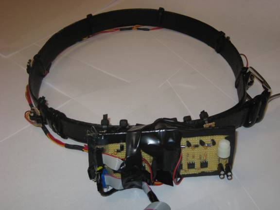
Belt:
The core user interactive component
of the system was the vibrating belt. This effect was achieved by mounting
eight small vibrators to the system. Each vibrator was designed to be
individually addressable and to exhibit full speed control through pulse width
modulation. The actual actuators used in this project were eight pager
motors. The specifications for these motors indicated they were capable of
operating in a range from zero to a maximum of four volts. At full voltage,
the current draw of an individual motor was approximately 100mA. Each motor
was mounted on a small piece of perforated board which provided a stable
mounting surface as well as a convenient place to form electrical connections.
The perforated board made connectivity easier, and also provided a rigid surface
for the vibrator to turn against, spreading out the vibration into a wider
region. Zip ties were then used to connect the perforated board to the belt.
Due to the movable nature of the zip ties across the belt this enhanced our
ability to dynamically reconfigure the belt for a users of varying girth as
well as solidly connecting each motor. Each of the motors shares a common
power wire (red wire) that was daisy chained around the belt. Additionally,
each motor had its ground connected to a controlled pin which selectively
connected to ground. This grounding was controlled by the microcontroller.
The motors were powered by a battery pack that was attached to the belt. This
battery pack used two AA batteries to provide approximately 3V to the motors.
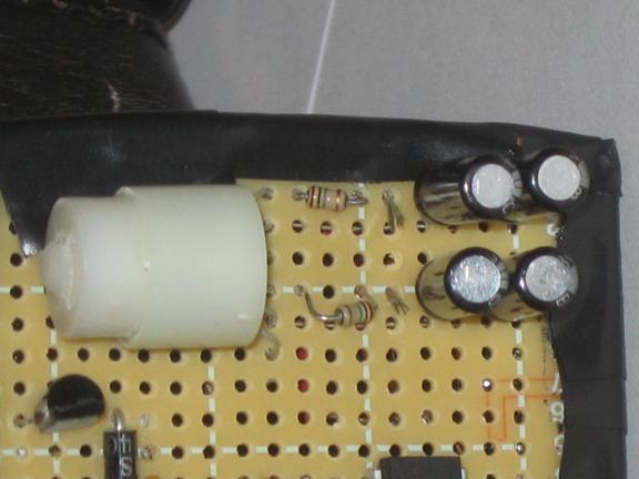
All eight of the motors also required external circuitry to drive them. The
circuitry, similar to the result from lab 5, performed optoisolation as well as
current buffering to allow the microcontroller to drive the motors. Each of
the eight motors uses the same circuitry which consists of a 4N35 optoisolator,
a 10,000 KΩ, a 1 MΩ resistor, 1N4001 Diode, .1µF capacitor and NPN
bi polar junction transistor. The optoisolator is used to isolate the
microcontroller from any nasty spikes that could occur in our motor driving
circuit. 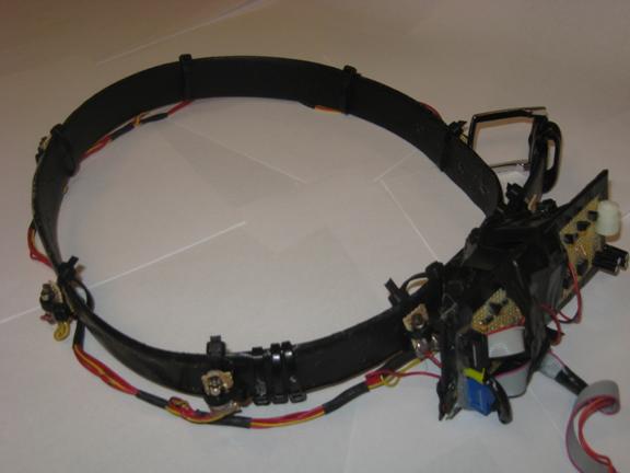
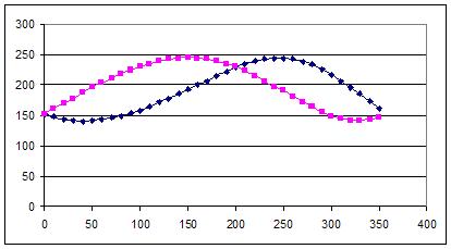
Dinsmore analog compass
The Dinsmore analog compass was used in our project to give our belt a constant compass bearing. The compass acts as a basic Hall Effect sensor that varies its output in response to a change in magnetic field. The sensor essentially measures the horizontal component of the Earth’s magnetic flux field. The sensor has six pins on it. The sensor produces two output voltages in response to changes in magnetic field. The two outputs were the value of a sine and cosine curve respectively at the angle of the compass. Each output pin has a reference 5 volt voltage and a reference ground. Both output voltages were also low pass filtered to reduce noise in the signals. We used a basic passive RC low pass filter to filter the signals. We used a 5 µF capacitor (two 10 µF capacitors in series) and a 10,000 KΩ resistor for our filter. These signals were then immediately fed to the ADC of the microcontroller. An external Vref is attached to provide the reference voltage for the ADC.
Digital Compass and Filter
GPS
The final piece of essential hardware in our project was the Global Positioning System module. The system uses medium earth orbit satellites that transmit radio wave signals to attain their current location, time and velocity. The GPS system needs at least 4 satellites to solve for position in three dimensions in order to avoid large position errors. Specifically for our project we used the GPS to measure Latitude, Longitude, UTC time and the correct date. For our project we used two GPS receivers a Motorolla Oncore GPS receiver and the MAP 330 receiver. The Oncore receiver transmits data in the Motorolla Binary format. The receiver requires about five volts to run with an externally applied battery pack and draws about 100 µA of current. The receiver also required an antenna to receive satellite signals. The antenna receives satellite signals at 1575.45 Mhz and requires 5 volts for optimal use. The Oncore receiver itself has 10 I/O pins. For this project we used 5 of the I/O pins on the receiver. We connected pin one (externally applied backup power) to two double A batteries, pin three (gnd) to ground, pin seven (1pps RTN) to ground and pin ten (TTL RTN) to ground. We received data from the receiver through pin eight (TTL TXD). The data transmit pin transmits data using TTL logic. Due to the inaccuracy of the Oncore receiver we decided to demonstrate our appointment manager using Professor Land’s Magellan Map 330 GPS receiver. The receiver transmits data in the standard NMEA format and is transmitted to our microcontroller through its serial port after passing through a MAX233 level shifter.
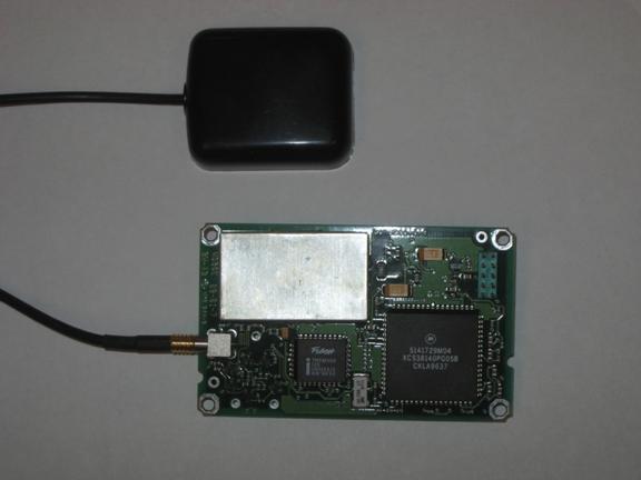
GPS Reciever
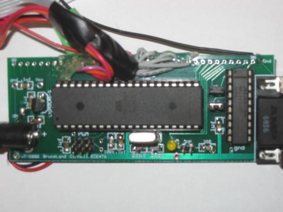
Microcontroller
The microcontroller used in this project was an Atmega644. This device was mounted on a simple breakout board created by Bruce Land and provided the functionality necessary to run the chip. The microcontroller was clocked by a 16MHz crystal which provided the necessary timing pulses.
Software
hapticgps.c The main function is the entry point of the program, it immediately calls initialize and then drops into an infinite loop. In this loop the program steps through a distinct procedure. First, it updates the bearing of the user by calling getCompass() in the compass header. It then calls getbearing(), another function within hapticgps.c. This function calls a function parseGps() in Compass.c which updates the coordinates if new information is available from the GPS receiver. With these potentially new coordinates it then calculates the new bearing to the destination using the great circle formula described in the mathematics section above to find the bearing between two points. It then scales and rotates this number to match, and returns with the resultant angle. This angle is then combined with the user bearing to calculate which motor needs to be powered on. The loop then checks in with the calendar in cal.c to see if the next appointment is pending with checkTimes(). If this results in a high flag for appointment flag, the loop then powers on the selected motors. Finally, it performs a check to determine if it has reached a waypoint. If, the current coordinates are within .0005 degrees of the destination, achievedWaypoint() is called to indicate to cal.c that the waypoint has been reached and it may move on to the next waypoint.
Motor.c
motor.c contains all of the code and functions necessary for driving the eight motors used in this project. The core of this file is the two interrupt service routines that occur when the free running timer0 match the value stored in OCR0A and when the timer overflows. On the match, the ISR turns off all motors by clearing the port and then turning on one of the motors on the port. Which of the eight motors this is depends entirely on the state currently set by the setMotor(int) function. This motor then remains on until the overflow occurs. Upon the overflow, the port is once again cleared and a second, different motor is set depending on the state set by setMotor2(int). This achieves an effective pulse width modulated signal for any of the 8 pins on PortC. Depending on what has been set by the setMotor functions, any of the pins could be the output. Since two pins are active at a time, there is a clear relationship between the two active outputs. Since each motor is only on for a section of the full timer count, the dc average is modifiable by adjusting OCR0A. Increasing OCR0A would increase the amount of time motor 1 is high while decreasing it would have the opposite effect. Since motor 2 is effectively the inverse of motor 1, this produces a situation where the output power is always the same, but is spread between two motors according to the value of OCR0A. This achieved a more continuous feeling belt, as it produced a smooth transition from motor to motor as one faded and the next grew in strength. Since the output power remained the same, it created an illusion of vibration moving seamlessly from motor to motor. Motor.c also contains a number of functions necessary for setting global motor speed and state as well as the functionality for turning it off. These functions all set or return internal variables and do not add additional functionality. Essentially, they form a protocol for other functions to interact with the motor control ISRs.
Cal.c
Cal.c contains the functions for managing and retrieving the waypoints and scheduled appointments. Essentially, it stores and retrieves this information from a large array. Once the time stamp on a waypoint has passed the checkTimes() function sets a flag and the waypoint in considered active. Essentially the waypoint will not be considered valid until the appropriate time has passed essentially giving the belt the ability to schedule destinations. Cal.c also has functions for reading the current latitude and longitude of the next waypoint and is called by the main loop for calculating bearing. Once the waypoint has been reached the function achievedWaypoint() sets the next waypoint but it is not considered active until checkTimes() checks to see if the time stamp has passed. Calc.c is seeded with waypoints from a connection to the terminal. This allows the user to update their calendar without rebuilding the project. To operate, the user must connect the device to a computer through the serial port and use the following messages:
!4,4,1,4,4,1,2,2,2,2,2 sets the gps coordinates and time in the following form: lat,hemisphere,long,hemisphere,hour,minute,month,day,year.
!C clears the current calendar.
GPS.c
GPS.c is primarily used to parse the data that is received from the serial input of the micro controller. Each time there is data on the serial port of the microcontroller UART raises a flag to trigger the UART character ready ISR. The ISR first determines that the data being sent is not a carriage return or a line feed. If the data is neither of these values then the byte is added to the r_buffer array. As each new byte is sent over serial r_buffer is slowly built byte by byte to contain one of the valid GPS messages that our receiver outputs. Since receiver can output dozens of messages in both the NMEA format and the Motorola Byte Format we added another conditional statement that would check if the data was one of the valid GPS messages we wanted. If the data was valid then the ISR would set a data ready flag and stop receiving data. If the data was invalid the data ready flag would be set low and the Microcontroller would continue to receive new data over the serial port. Once the data ready flag was set the function parseGps was called to parse the data out of the valid message. All valid messages are always the same length so all we had to do was parse the message into the appropriate data fields. Once parsing is complete the data ready flag is set low and the microcontroller receives serial data again. Additionally GPS.c had additional functions to return each of the parsed fields.
Compass.c
The main purpose of Compass.c is to interact with the dinsmore compass and calculate the current bearing that the compass is reading. The compass outputs two voltages that change in response to horizontal changes in magnetic flux. The function getCompass() first calls another function updateCompass(). updateCompass() is a dual state state machine meant to read the digital values of the two output voltages of the Dinsmore compass. The state machine reads the 8 bit value on the ADC channel for one of the output voltages then changes it state so on the next read it can get the value. GetCompass() then calls updateAdc() which reads a new sample from the A/D converter. Each time updateCompass() is called the value of the admux register is changed so that updateAdc() will read both output voltages of the compass. GetCompass() then calculates the angle bearing of the compass and returns this value.
Things that did not work
We had considered using only the bearing provided by the GPS receiver. However, we quickly discovered that this is only accurate when the user is moving quickly. This forced us to continue using the analog compass we had begun with.
We also initially intended to only power one motor at a time. This would have allowed us to use the motor speed as an indicator for urgency. However, we discovered early on that the feel of an eight motor systems was jerky and unconvincing. We abandoned the one motor approach in favor of turning two motors on using pulse width modulation to create a smoother feeling.
We initially planned to mount all of the electronics on the belt. However, we found that the rapid vibration of the belt was damaging some of the connections on the MCU so we left this piece of hardware handheld.
Results:
Lag and timing
Since our project was only required to operate as quickly as a human could process the information, we had very few timing issues. However, the compass had a distinct lag when settling which depended on how rapidly and how far the user turned. This settling time was noticeable, and the compass was sometimes returning erroneous data. However, it would settle so the problem was more of a minor annoyance than a serious issue. This compass time was the limiting factor for the project, so no other timing or delay issues were noticed.
Accuracy
Our system only needed to be as accurate enough to not be noticed by a human. Because we only had eight motors, this was in essence the limiting factor on our accuracy. However, both compass hysteresis and the large deviation of the GPS, on small scales, the system was somewhat inaccurate. However, when navigating to locations for than approximately thirty-five meters away, the system did not exhibit any noticeable inaccuracy.
Safety
We were very careful to design and implement our project in a safe manner. While working on the circuit we followed all the necessary safety precautions to protect ourselves and those around us. Unlike many of the other projects, our project was battery powered, minimizing the current and voltage available to harm the user in case of catastrophic failure. We were also very careful to insulate bare wires and prevent shorts to keep from harming the user in any way. We also attempted to minimize sharp edges where possible.
Interference
As our project did not transmit RF signals, it is unlikely it could interfere with other projects. Additionally, since it was battery powered, it would be unlikely to cause any sort of problem through noise. Though the motors do produce small electromagnetic fields, the effect would be trivial on most devices.
Usability
Our project is fundamentally usable. Since the goal is to be an intuitive, almost subconscious interface, it is usable with minimal instruction and by almost anyone. Additionally, since the belt does not require any type of visual or aural interface, it is as just as usable for a blind or deaf individual. For the blind, this project could be a great help as it provides an interface to a GPS navigational system that does not require the use of sight. For normal use, this system can simply be donned and then forgotten. It does not require any user input during operation and should manage itself and be usable without any real user interaction.
Conclusions:
Expectations, results and possible improvements
Our project met our expectations as a functional navigational system. The ability of the vibration to shift around the body as the user turned surpassed our expectations. Due to the motor fading we implemented, the transition felt very smooth and continuous. The vibrations were subtle, and after about 30 minutes of use, both our testers stopped noticing the discreet vibrations and instead just felt a “feeling”. Additionally, we were pleased with our ability to combine GPS with a haptic belt. The waypoint finding was flawless and again felt very smooth. We were somewhat disappointed with the speed and accuracy of our hardware devices. The GPS receiver accuracy was on the order of tens of meters. While this is standard accuracy for a non WASS receiver, it was disappointing as it made it forced us to use widely spaced waypoints. However, even with this degree of accuracy, the device was extremely functional and useful.
If we had more time and a greater budget, we would have liked to incorporate a higher resolution GPS receiver. Unfortunately, this was beyond our budget as WASS receivers are generally fairly expensive. Additionally, it would be nice to add a wi-fi module to the device for interfacing with a web calendar. Again, the wi-fi module would have placed us outside our given budget and was abandoned early on. Finally, in retrospect it may have made sense to also add an accelerometer based navigation system to compensate for the poor GPS reception. However, designing this type of system would have been a project in and of itself.
Were we to attempt this problem again, we would look more closely at the unique issues of wearable computing. Due to the gait and vibrations of a user, some of the electronics were badly shaken in our initial design, sometimes causing loose connections or failure.
Intellectual Property Considerations
Though we did not repackage any code, we did use a uart header provided by Joerg Wuncsh to interact with the serial port. This header was provided under a “beerware” license. We have retained the license declaration and intend to purchase Joerg Wunsch his favorite malt beverage on the off chance we ever meet him. Additionally, we referenced a prior compass project created by Chun Cheng Wang and Leung Kin Chiu in 2004. There project proved a valuable resource for learning how to use the compass. Though our aims diverged rapidly and we did not use code from their project, it was incredibly helpful in our early design work. Of course, we also owe a debt of thanks to Bruce and all of the tireless TAs who made it possible for us to complete this project.
Ethics
We strived to maintain the IEEE code of ethics throughout completion of this project. Our project is reasonably safe, and we have no reason to believe it would present a risk to any individual. However, we acknowledge that due to a being prototype hardware, there are some risks of use. We chose to minimize these risks by creating a very low power, battery powered system with no significant currents or voltages.
Beyond physical damage, we also chose to ensure that we maintained a safe and supportive environment around us in lab. To ensure that we did not make any individuals uncomfortable, we made efforts to maintain our work environment and to interact with our peers in a civil manner. At no point did we discriminate in any manner and we strove to treat all our peers well, regardless of any characteristics they exhibited. We did not slander or Additionally, we strove to assist other groups when possible, providing guidance on some aspects of the Atmega644 that we had become overly familiar with.
We were very honest both with ourselves and others regarding our abilities. We attempted only technical procedures we were competent to undertake and deferred to Bruce and the TAs when necessary. At no point did we present ourselves as more capable than we were. When we encountered problems we requested and received criticism and suggestions both from our peers and the TAs. When we were found to be in error, we acknowledged our mistakes and were thankful for the advice and guidance.
In analyzing our system we were honest in our assessments and did not present our device dishonestly. We were also honest in our weekly assessments and attempted to convey our actual progress. Our assessment of the final result has also been completely honest.
Legal considerations.
Our project did not include any transmitters. While there was a wireless receiver, it was a part of an OEM GPS receiver that already meets all relevant FCC regulations. Our project did not use any regulated materials or technologies and we do not have any outstanding copyright or patent violations, particularly as we do not intend to monetize this design.
Appendix A:
Source Code
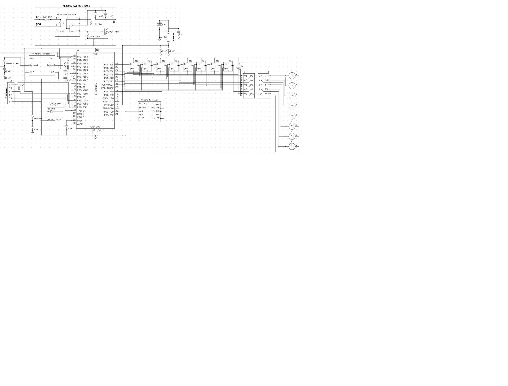
Appendix B: Schematic
Appendix C: Cost Information
|
Device |
Cost per unit |
Number used |
Total price |
|
Atmega644 |
Free sampled |
1 |
$8.00 |
|
Oncore GPS Receiver |
$5.00 |
1 |
$5.00 |
|
Antenna |
$8.00 |
1 |
$8.00 |
|
Null Modem Cable |
Free (owned) |
1 |
$0.00 |
|
Max 233 Level Shifter |
Free (Sampled) |
1 |
$0.00 |
|
Old belt |
Free (Owned) |
1 |
$0.00 |
|
AA batteries |
Free (Owned) |
4 |
$0.00 |
|
9 Volt Battery |
$3.00 |
1 |
$2.00 |
|
Dinsmore Compass |
$20.00 |
1 |
$20.00 |
|
Pager Motors |
$0.79 |
8 |
$6.32 |
|
Perf Board |
Free (Owned) |
1 |
$0.00 |
|
Optoisolators |
$0.00 |
8 |
$0.00 |
|
Battery case |
$1.00 |
3 |
$3.00 |
|
Pins |
$0.05 |
28 |
$1.40 |
|
NPN BJT |
$0.00 |
8 |
$0.00 |
|
|
|
Total |
$53.72 |
Appendix D: Work Breakdown
Member Tasks
Abe Cantwell
Circuit Design
Circuit Debugging
Soldering and Final Belt Assembly
Software Design
Software Debugging
Report
Webpage Creation
Balu Nair
Circuit Design
Circuit Debugging
Soldering
Software Design
Software Debugging
Report
Webpage Creation
References
http://wa5rrn.com/oncore.htm (Motorolla Bit Format Standard)
http://www.gpsinformation.org/dale/nmea.htm (NMEA Standard)
http://www.gpsvisualizer.com/calculators.html (Great Circle GPS calculator)
http://mathforum.org/library/drmath/view/55417.html (Bearing Between two Points)
http://www.eng.usf.edu/~rjguerra/handyboard/dinsmore/dinsmorecompass.pdf (Dinsmore Compass Information)
http://www.societyofrobots.com/member_tutorials/node/309 (AVR Basic EEPROM Tutorial)
http://instruct1.cit.cornell.edu/courses/ee476/FinalProjects/s2004/ccw27/index.htm (Digital Compass 476 Past Project)