Ryan Dunn (rjd38 at cornell.edu)
Dale Taylor (dat38 at cornell.edu)
Introduction
This goal of this project is to make an effective, low-cost 3D scanner.
Summary
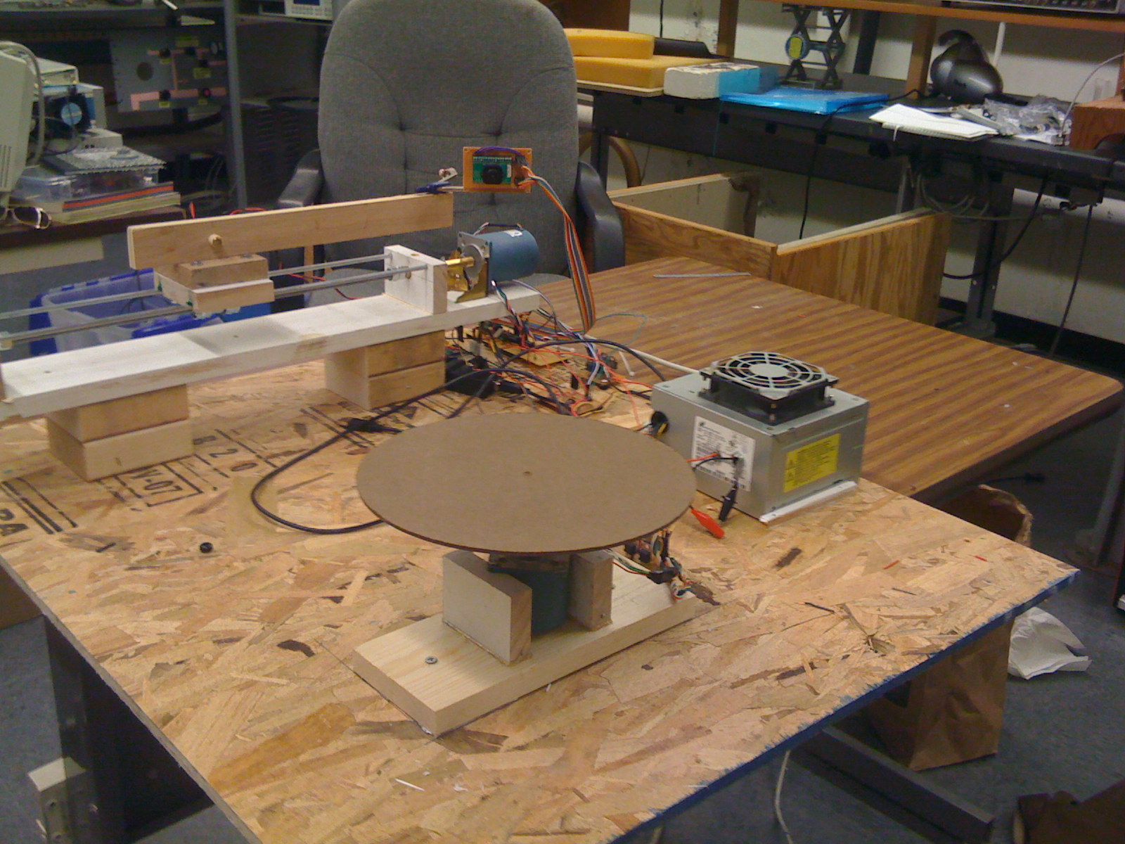
Our project implements the hardware necessary for a laser triangulation 3D scanner as well as a PC user interface for controlling the scanner and acquiring data via an Ethernet connection. Our scanner facilitates 360-degree scans through the implementation of a rotating sample platform. Each position of rotation is scanned using a linear actuator to increase resolution. While our scanner is capable of producing all data necessary to compute and construct 3D representations, we determined that actual mesh reconstruction was out of the scope of this project. Nevertheless, our source code contains the required mesh data structure and OpenGL utilities to construct 3D meshes for those who wish to build on our work.
High Level Design
Rationale
While 3D scanners are by no means new technology, they are still well out of the price range of the average individual or small business owner. Our goal was to design a 3D scanning hardware package and computer control interface for under $75. Such systems are incredibly useful for those interested in any sort of product or graphic design as well as those looking for a way of documenting items. A 3D scan provides a much more complete representation of an object that is not currently available to the average person.
3D Laser Triangulation Scanning
The way that a 3D Laser Triangulation Scanner works can be easily explained using simple geometry and trigonometry. The basic setup consists of a laser line diode, a camera, and a sample. The distance between the camera and laser diode, d, is fixed and known. The laser line is projected onto the sample and is monitored by the camera. Using the known parameters of the camera, the angle theta between the laser, camera, and laser line on the sample can be calculated. Upon computing this angle, the distance between the laser and the sample, x, can be determined using the formula x = d*tan(theta). With a linear actuator we can map the distance x over different values of y as actuation occurs. After the scan has been completed, these points can be reconstructed in three dimensions assuming z is proportional to the height of the point in the image (exact values of z are determined using the known parameters of the camera).
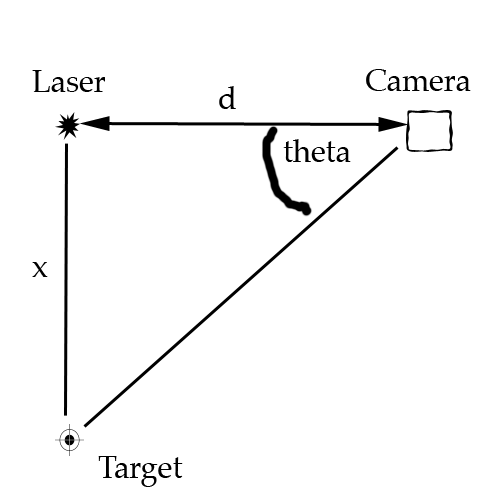
Laser Triangulation
Logical Structure
In order to extract physical coordinates from a contour line like the one explained in the math above, we will use a camera and a laser line. The laser is by far the brightest element in the image, so the line it makes on an object is easily distinguishable from the rest of the image.
If a number of contours lines are taken from an object, eventually, the combination of the extracted physical coordinates will begin to match the shape of the object rather closely. Our scanner uses this concept to create a digital representation of the object it scans. The laser and angled camera a poised on a linear actuator that is hooked up to a stepper motor. The stepper motor gives us relatively precise control over the location of the laser and camera. This allows the scanner to sweep across the face of an object. While a sweep alone is capable of creating a good representation of an object’s surface, it inherently misses over half of the object it scans. To solve this problem, the object to be scanned rests on a platform that spins with the assistance of another stepper motor. Scans from multiple sides can be combined in software to create a more complete representation of the object.
Digitally reconstructing the object and processing the images from the camera to extract the contour lines is computationally expensive. For this reason, the Mega644 is only used for data acquisition and system control. All of the computational work is done by a computer attached to the scanner system. In order to make data acquisition happen at an acceptable rate, the microcontroller’s connection to the computer is a 10 base T ethernet connection utilizing the UDP protocol. UDP is lightweight and fast, making it perfect for our use with the microcontroller in our project.
Once the data actually reaches the computer, it processes the image to find the laser line. The set of points that make this line are added to a polygon mesh. This mesh is the digital representation of the object.
Program / Hardware DesignProgram Details
The main purpose of the Mega644 in this project is to control hardware, as a result, the hardware and software are closely linked by component. The most important tasks of the microcontroller include:
- configuring the camera
- capturing the camera data
- sending camera data over ethernet
- reacting to network commands
- running the stepper motors
Mega644
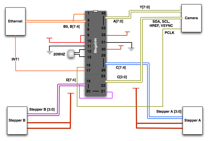
Hardware Schematic
The way that our code is organized makes the MCU the slave to the PC workstation. The MCU is capable of capturing data from a camera, transmitting and receiving data over an Ethernet connection and controlling stepper motors for scanning actuation and rotation. The MCU receives commands through an interrupt driven process and then takes the appropriate state according to the command received. Upon completion of command execution, the MCU sends a message to the PC confirming that the task was finished. This, we found, is critical for automating scanning as well as maintaining instruction concurrency between the two parties.
Camera
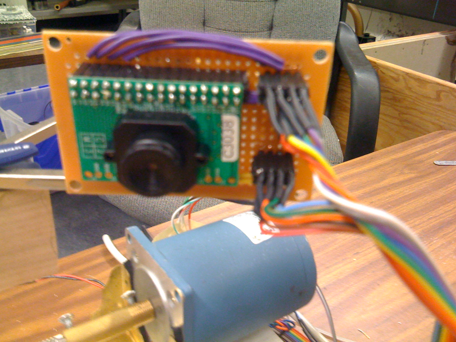
We ended up choosing the C3080 Color Sensor Module, which uses the OV6630 CMOS image sensor. The C3080 comes with an adjustable focus f4.8, F2.8 lens with a field of view of 34.3 x 20.7 degrees and a resolution of 356 x 292 pixels. The OV6630 is easily programmable to output data in several different formats and a variable clock rates. Because of the limited processing power and memory resources of the Mega644, this was a very attractive and practical module for us.
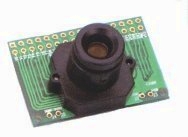
C3038
In order to configure the camera for our needs we need to program the registers in it to adjust a few settings. This is done using the I2C protocol on the Mega644s TWI interface, which even provides the ability to use an internal pull up register. This is activated by writing to the port when it is in input mode. The functionality for actually programming the cameras registers is provided by Peter Fleurys TWIMaster .
Determining which registers to program in the camera was an interesting task. In order to be able to capture and send data progressively, we need to slow down the clock rate significantly. At first we were having trouble figuring out why few other settings made a difference in the image quality. Only after a few hours of trial and error, we realized that the slow frame rate caused a rather long exposure time. Fortunately, this lets us see our object to be scanned, even if the scanner is shaded to maximize the laser line visibility.
The output mode that we specified was one line RGB. In this mode, all of the data comes out of one port, and it is read from the sensor in its native Bayer format. In Bayer image formatting, the sensor is arranged BGBG... GRGR... each line. This results in 50% of the pixels being green, and 25% each being red or blue.
After configuring the camera, the rather daunting task of acquiring data arises. The main issue lies in the fact that a full image frame is over 100kB, and the Mega644 only has 4kB of EEPROM (or a few more KB of Flash that we would destroy rather quickly). Our only option for getting all of the data from the image frame is to send each line during the break in-between lines, as data is repeated on HREF low. Below is a diagram showing the basics of how capture works. The software watches 3 external interrupts for the VSYNC (start of frame), HREF (start of line), and PCLK (start of pixel) sync signals. The interrupt driven code is fast and effective in data acquisition. Example output for the sync signals is included under the diagram.
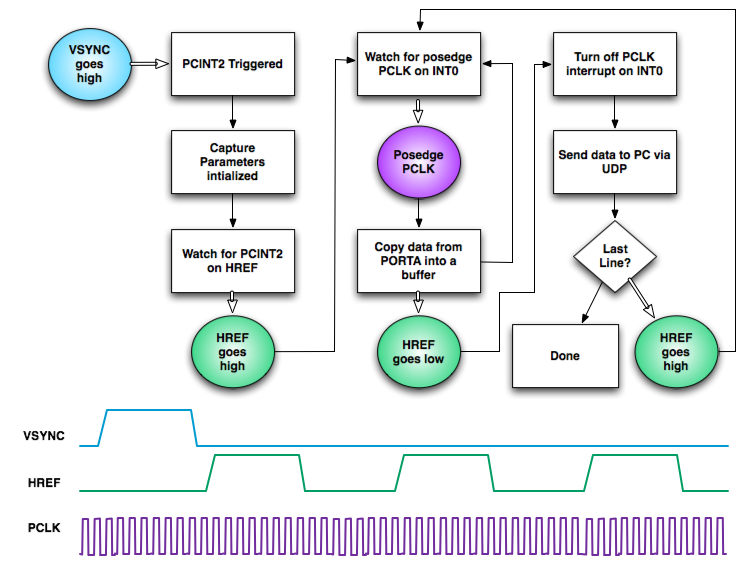
Camera Capture Procedure
Ethernet
Network Device
Since the Mega644 has minimal onboard memory and image data tends to be very large, we needed a method of communication that would allow us fast data transfer with minimal overhead. We chose Ethernet communication due to the high data transfer rates as well as the relatively low overhead of sending a packet of data.
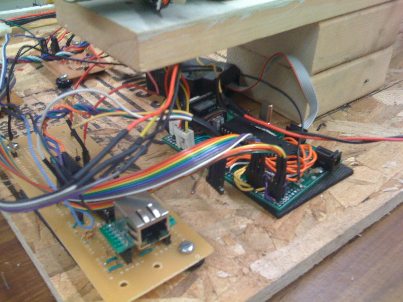
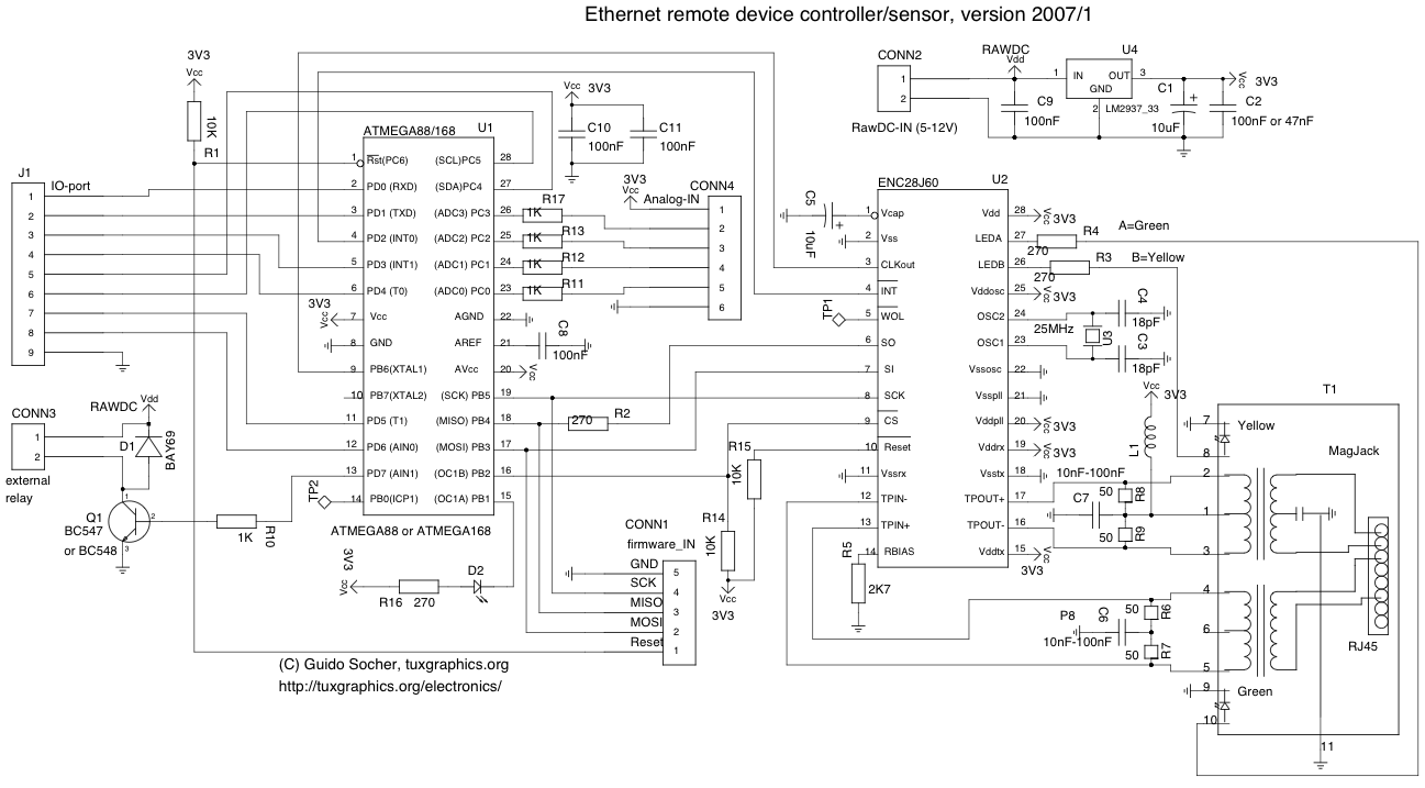
Ethernet communication was facilitated through the use of the ENC28J60 stand-alone Ethernet controller with SPI interface. The ENC28J60 connects easily to the Mega644 using SPI and then onto the local network using a standard Ethernet MagJack. We built our hardware and configured our ENC28J60 with help from a tutorial through TuxGraphics.org. This was an extremely helpful resource. We found a great circuit diagram here that worked well for us as it induced little noise in a circuit that is highly sensitive to such disturbances.
While the ENC28J60 provides the means for transmitting packets over an Ethernet connection, all of the packet formatting and communication protocols must be taken care of by the MCU. We decided to use User Datagram Protocol (UDP) since it requires the least amount of overhead and packet loss was not a major concern since we are transmitting over a closed network. We used source code from TuxGraphics as the basis for setting up UDP communication as well as for communicating with the ENC28J60.
Sending Data
The image sizes we dealt with were on the order of 100KB so storing an entire image on the Mega644 was out of the question. The amount of time between each line of image data was long enough for us to send a packet containing the entire previous line (~350 Bytes). Thus, we never needed to store more than one line of image data at a time and were able to transfer an entire RGB image in less than one second. The ENC28J60 handles sending through an onboard transmit buffer of variable size (up to 8KB). This send buffer is loaded through SPI and then transferred onto the network by setting a register on the ENC28J60. We decided to send each packet immediately after loading into the send buffer.
The source code from TuxGraphics only implemented responses and not code for constructing headers for initiating communication. We wrote code to send packets to a specific IP and MAC address. This was initially difficult, as two checksums need to be computed as well as several other header parameters set. We download an open source program, Packet Peeper, to monitor our Ethernet communication. This proved to be incredibly helpful in debugging and testing our UDP communication. Our code works well, however there is a significant amount of overhead that goes into computing the packet header each time a packet is sent. It would be worth looking into ways to pre-compute a header if one was very pressed for sending time.
We encountered difficulties with packet collision when we first started sending data from our camera to the workstation via the ENC28J60. These collisions cause the ENC28J60 to lockdown and stop sending packets all together until it was reset and reconfigured. We investigated this erratic behavior on the device’s errata and were able to come up with a fix that allowed us to continue sending packets regardless of whether or not there was any sort of error without having to completely restart the system. Without this fix we would have not been able to use Ethernet communication as the errors would often occur after as few as 20 packets.
Receiving data
Receiving data sent from the workstation is a vital part of our program, as all commands are initiated from the workstation. The ENC28J60 has a receive buffer that holds all incoming packets until they are checked by the microcontroller. Fortunately, the ENC28J60 has an interrupt that triggers whenever a packet is loaded into the receive buffer. We incorporated an external interrupt on the Mega644 that monitors this pin and checks the receive buffer whenever the interrupt is triggered. This provides two advantages, one being that we don’t waste time checking the buffer when there is nothing there, and two being that the microcontroller receives commands as quickly as possible after they are sent.
While interrupt driven command retrieval is a great way to direct the microcontroller, there are times, such as when the camera is capturing data, when we do not want the Mega644 to be interrupted on PORTD3, therefore we toggle our interrupt on and off according to the state of the microcontroller. Whenever the scanner is moving any of its parts communication is always enabled so we can quickly tell it to stop if its behavior becomes self destructive or erratic.
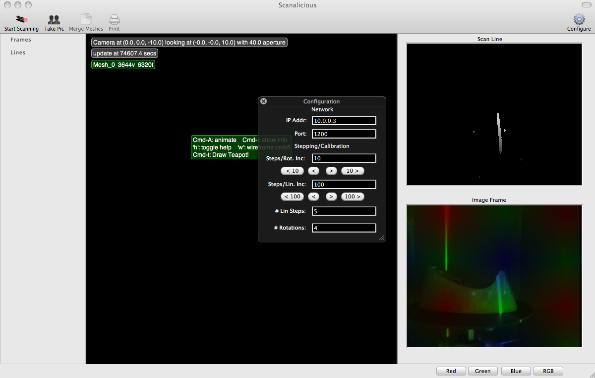
Scanalicious.app
We wrote a test application using multiple flavors of C that handles all the communication with the scanner. It is responsible for sending commands to the scanner, automating scans, and reconsructing the received image data into an actual mesh. While the meshing code does not work yet, the interface is sufficient for basic scanner operation. The code for the application (OS X 10.5 only) can be obtained below in the source code section.
Stepper motors
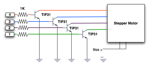
Stepper Motor Circuit
Due to their high precision of control, we decided to use stepper motors for our linear actuator and platform rotation motor. We were lucky enough to find two stepper motors in the lab for free. We located a great source online for determining the pin layout of the stepper motor here. We used four TIP31s to drive each motor, since there are four pins on each motor. We found that the steppers still source a large amount of current even when they are not moving. We decided to fan cool the circuit driving the actuator, as it often got incredibly hot.
Laser
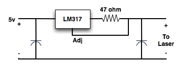
Laser Driver
Lasers require a very constant current source, to keep them from burning out. Above is our laser driver circuit.
Hardware Issues
The largest issue that we encountered in hardware was with our camera. Originally we had planned on using the ST Micro VS6650. After thoroughly familiarizing ourselves with the camera, we still failed to get it working. It was cheaper and higher resolution that our current camera (the c3038), but the support circuit was significantly more complicated. Also the camera required a level shifter, as it operated at 1.85 volts. This unfortunately was a major setback in our progress.
Results
Speed
The overall speed of our data transfer is fast for a microcontroller such as the Mega644. An image of approximately 100KB can be transmitted in approximately 1 second. A conservative estimate for our data transfer is ~100 KB/s. During scanning mode, the total time of the scan is limited by the speed of the stepper motors. We have found that although stepper motors are incredibly accurate, it is a tradeoff for speed. All in all, the speed of the scan is not an important or limiting factor for our project.
Accuracy
The accuracy of our scanner is ultimately limited by (1) the diameter of our laser line, (2) the ability of the camera to focus on the sample object, and (3) the resolution of our camera and (4) the stepping sizes we can achieve. The width of our laser line is ~2mm, however different materials have different diffusion characteristics and this value can vary greatly. From all of our testing we have been able to focus the lens on the object so that it is clear within the frame. Our stepper motors can step in very small increments so they are not limiting factors. The major limiting factor to our accuracy is the resolution of our image. Since the camera only has a resolution of 356 x 292. Since we have not constructed meshes yet, it is difficult to say the exact accuracy we can achieve.
Safety
The one major safety consideration is the laser. Direct laser contact with the eye is known to cause permanent eye damage. We have made this as safe as possible by installing a physical switch to turn the laser on and off. In addition, the entire scanning region is enclosed by cardboard so that the laser travels no further than the board the scanner is mounted on. One must take extreme care however when scanning objects with high reflectivity as the laser shield will not protect from this. In cases such as these it would be best to enclose the whole setup in cardboard or another material that would block laser light.
Usability
One of the major goals of this project was to bring 3D scanning capabilities to the average person, thus the usability of the device was an important consideration. The user interface aims at doing this by making all scanning processes completely automated. The user must (1) place the object on the sample table, (2) set the number of steps and number of rotations, and (3) press start. From this point on the scanner will output all appropriate data. As will any new technology there will be a curve, however we have tried to minimize this by performing several tasks for the user.
Conclusions
How did this meet our Expectations
All in all our final hardware met our expectations quite well. We initially set out hoping to use a higher resolution camera, however due to difficulties we ended up using a lower resolution, less powerful camera. Other than that, our linear actuator, Ethernet setup, and rotating sample holder came together as planned. On the software side, our final results fell slightly short of our initial expectations. We had initially hoped to be able to build meshes using the image data we collected, however complications on the hardware side did not allow us enough time to adequately test our mesh construction software. Nevertheless, we have designed and built a 3D scanning module that will automatically collect all the data necessary to produce a three-dimensional model of nearly any shape. Overall, we consider the project a success.
How does our design conform to the applicable standards
The only real applicable standard used in this project is the User Datagram Protocol (UDP). All information sent between the computer and the microcontroller is formatted using standard UDP packet formatting and headers.
Intellectual property (using code of someone else or code in public domain)
Appendix
Code
The source code for the MCU is listed here, but the entire project, including the Mac application is available via SVN in the repository listed below
- mymain.c
- enc28j60.h
- enc28j60.c
- ip_arp_udp.h
- ip_arp_udp.c
- i2cmaster.h
- twimaster.c
- Source Code (google code)
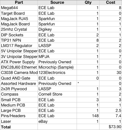
Costs
Work Distribution
Though most of the work was done together, the work distribution was roughly this:
Ryan Dunn
- Ethernet
- Laser
- MCU Networking
Dale Taylor
- Camera
- Mechanical Devices
- Workstation Application
Relevant DataSheets
Vendors
Useful Links
- Special thanks to Bruce Land and all of the 4760 TAs!
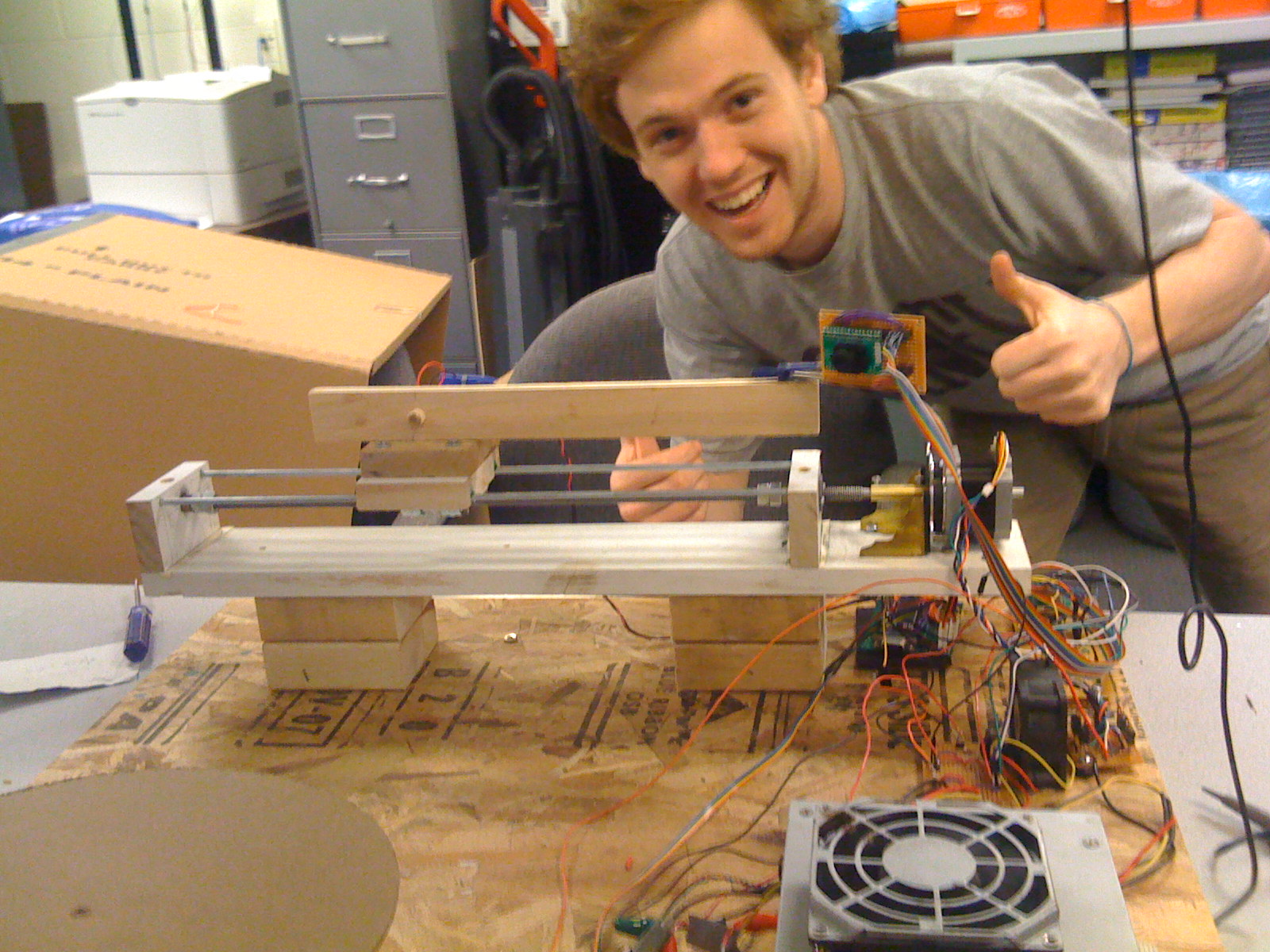
Photos