Introduction
For our final project, we built a mechanism that spun a linear array of seven LEDs at a velocity that made it appear as if a message was being displayed using persistence of vision for the human eye. To accomplish this, we first had to design and build the hardware components, which may have been the most difficult portion of this entire final project for reasons discussed in detail later. The hardware mostly consisted of a spinning wood platform, a DC motor, LEDs, any other circuitry (including the microcontroller). We decided to begin with the construction of hardware because there would be no way to test the code without functioning hardware. The code itself uses a modified version of the 7x5 ASCII character set included in a prior lab to create a message across the spinning wood platform. With precise timing of the angular velocity of the platform, an individual byte of data (containing either ON or OFF for each LED) can be sent at the appropriate time so that a visible message appears. Also included in the code is the ability for the user to decide the color of the message (red, blue, or green) and the characters included in the message by using an attached keypad.
High-Level Design
The motivation for this project came from multiple sources. We had seen and were impressed by other similar devices as seen on YouTube. However, in those devices the LEDs were not programmable. It seemed reasonable to us that a consumer would most likely buy such a display only if they had control over the message(s) displayed. With that in mind, we also wanted to create a display that had a spinning circumference large enough to display a comprehensible message, not only a small string of characters. And, for added complexity and flare, we decided to make the LEDs tri-color.
From our research, in order to get the effect of persistence of vision, an LED or other light should blink at fractions of a second [1]. Thus, in terms of rotations per minute this meant the motor must have been chosen so it operates at an angular velocity with the additional weight we planned to connect of about 1800rpm. The only other math that needed to be completed was in the construction of a voltage divider for pin2 of the LEDs, but it is discussed in detail in the hardware section of this report.
The main logic used in the spinning LED display was to control the ON or OFF state of the individual LEDs. A 7x5 binary character set was created based on the active-low configuration of the LEDs, so a 1 corresponds to OFF and a 0 to ON. For us it seemed reasonable that each color was controlled by a separate port on the microcontroller, with pin1 (Red), pin3 (Blue), and pin4 (Green) of each of the seven LEDs connected to PORTA, PORTB, and PORTC, respectively. That would leave an empty pin for each port, which we arbitrarily decided would be pin0. Also, in a similar manner, the keypad had seven pins connected to PORTD and left pin0 of PORTD unconnected. Of course, other logic was included to allow use of the keypad, but the details are discussed in the Program Details section below. A complete listing of the code is also available.
Since we were able to find hardware that suited our project goals, there was not a significant amount of hardware/software tradeoffs. The only modification we had to make to software in this entire project as a direct result of hardware was the timing of the LEDs blinking. However, this only occurred because we did not know the exact angular velocity of the motor with all of the components connected to it. But with a small amount of trial and error, and a short test program, we quickly made the modification.
Standards, patents, copyrights, and trademarks were not an issue with this project. The issue of safety was taken into serious consideration and is discussed in the Results section of this report.
Program Details
The design of the program took a significant amount of time because of the complexity in the different functions we wanted the Spinning LED Display to perform. These functions were to be controlled by the keypad and consisted of:
Before describing the software design we would like to note that some of the code was borrowed and modified from other code. Firstly, the array of letters for used to blink the LEDs is based on the array from video_codeGCC644.c for lab 4 of ECE 4760. It was modified to just use the capital letters and the bits were inverted and the letter is oriented differently in the array for ease of use. Secondly, the debounce state machine used for the key pad was taken and modified from debounceGCC644.c test file from lab 2 of ECE 4760.
The software for this project is split into two sections. The first section is the displaying of the message. This is done in a timer compare match ISR in order to keep the LEDs blinking at a constant rate and prevent distortion of the display. The code in the ISR simply checks for which color the letter is to be displayed in and it outputs each byte from the array for the corresponding letter, where each bit corresponds to a specific LED. The rest of the ISR just increments the variables keeping track of which letter it is displaying and which byte it is displaying (and the variable keeping track of letter color if the user sets the display to display each letter in a different color), the variables are incremented or decremented to allow the software to cycle through the entire message over and over for persistence of vision. The timing for the ISR was done on the guess and check method and remains constant.
The second part of the software is the keypad reading and the creation of the array of the letters to be displayed. The debounce state machine is used to make sure a button is just read as a single push and not several pushes. A set of nested if statements is used to determine what to do. Input from the keypad can be used for three things. Firstly, the letters to be displayed are represented by two digit numbers corresponding to their position in the alphabet (A = 01, Z = 26) which is stored in an array to be used for the displaying ISR. Secondly, if the talk button is pushed on the keypad, the next button pushed corresponds to the color the letters are to be displayed in (1-3 are single colors; 4-6 are multiple colors with each number corresponding to a different starting color). Thirdly, if the reset button is pressed the software switches between the displaying state and the user input state. When in the input state, the LEDs stop blinking.
Hardware Details
In order to reach our goal of making a programmable and tri-color spinning LED display, we had to make a platform large enough for all of the components. We decided to use a circular platform of a diameter of about 12 inches to have enough space for all hardware and also have a circumference large enough for a decent sized message. Also, because of the diameter, we needed to use a total of 28 individual wires (four for each LED) to extend to the MCU. The MCU could have been brought closer to the LEDs, but for balancing purposes and torque considerations, we decided to place the MCU near the center on the opposite side of the LEDs.
The hardware may have been the most challenging aspect in completing the final project. Since neither of us have any experience in mechanics, building the actual spinning LED display presented more of a challenge than originally thought.
Our first problem was finding a motor that would be large enough in size, have enough torque, and rotate at the proper rpm range. From our research, the spinning led will appear to display a message to the human eye only if the frequency of rotation is high enough. Also since we planned on placing all of the circuitry on top of a spinning platform on the motor, we needed a motor with enough torque to be able to handle the weight and still rotate faster than the minimum 1800rpm motor we wanted to use. Eventually, we found a motor that has all of the capabilities we needed, but finding one took a significant amount of time.
The next problem we had to deal with was keeping the platform on the motor. The motor has a shaft that spins, but attaching the platform requires welding it on to the shaft. To do this with a wood platform, screwed in TEE nuts to top and bottom of the wood and put the shaft of the motor through the center of the TEE nuts. Then, all we needed to do was to weld the TEE nuts to the shaft of the motor. Unfortunately, neither of us are trained welders, so we had to make several phone calls and ask for favors from friends to get the welding completed. We found a friend of friend who was not exactly a professional welder but had enough experience to do this simple connection free of charge. As a result of our welder’s inexperience, we only asked him to weld the topmost part of the shaft to the top TEE nut.
Another minor difficulty occurred because of all of the soldering we had to do. We did not schedule enough time to solder all of the connections, so we ended up a little bit behind schedule. There were at least 60 connections that we had to make, plus the additional connections for the target board.
Now to describe the circuitry and operation of the spinning LED display:
First, we need to describe the operation of the LEDs. All of the seven LEDs we purchased had the internal circuitry as shown below:
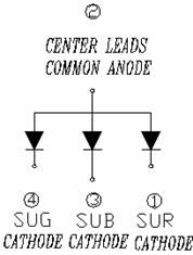
Taken from RadioShack website: [3]
As can be seen, the top pin (pin2) must be at a higher potential than pins 4, 3, and 1 in order for current to flow to the lights. Thus, pin2 must be set to high and the other pins are active low. The difficulty arises because the maximum voltage for the red led is only 2.5V and 4V for the green and blue, so we cannot simply set the output to 5V. We decided to use a voltage divider to make the voltage 3.5V for every pin2. With the resistors in the lab, we built and soldered together the following voltage divider circuit:
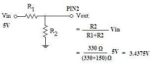
With R1 being the series combination of two 75Ω resistors, and R2 equal to 330 Ω, the voltage Vout is below the 4V maximum for the green and blue pins. From experimentation, we discovered that the 3.4375V output of the voltage divider worked well for all colors of LEDs, even the Red. After all of the pin2 connections were soldered, we soldered the wires connected to the red (pin1), blue (pin3), and green (pin4) of each of the seven LEDs to their corresponding pin in PORTA, PORTB, or PORTC. The keypad also needed to be soldered. For added flexibility in the placement of the keypad, we soldered wires to make the connection from the keypad to the custom PC board.
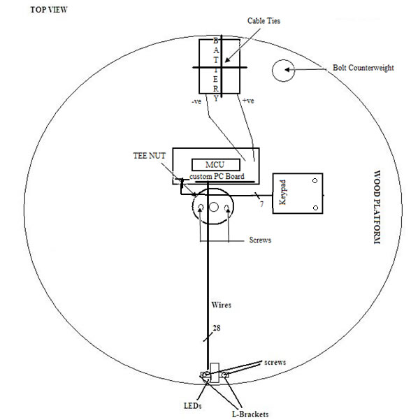
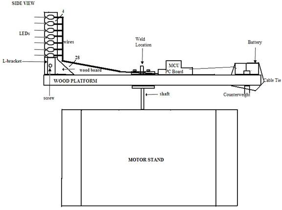
After all of the soldering was complete, we attached the all of the LEDs to a piece of wood via hot glue. That piece of wood was then screwed into the wood platform with the use of two L-brackets. The wires from the LEDs to the custom PC board as well as the voltage divider described earlier were taped down using highly adhesive electrical tape. The keypad and custom PC board were screwed into the wood platform to keep from becoming a safety concern. And, finally to keep the battery secure, we created three holes: one on the left, one on the right, and one near the top of the battery in the wood platform. Then, we used cable two ties to tie down the battery. An additional counterweight consisting of a bolt, washers, and a wing nut was added to the wood platform near the opposite side of the LEDs for stability purposes.
The stand for the motor was the last hardware component to be built. Using half-circle pipe clamps, we screwed the clamps tightly around the motor into a 6 inch oak board and built three more walls with the remaining oak pieces, all connected via wood glue. Initially, we attempted to screw and then hammer the boards together, but the oak boards were so dense that the screws broke and the nails bent dramatically. Two figures below, a side view and top view, can be referred to for a visualization of the hardware:
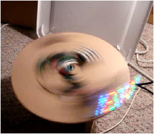
Here are also a few actual pictures of the spinning LED display.
Results
After testing hardware functionality and gauging the correct timing, testing of the code was a success. The spinning LED display appropriately displayed a visible message without blurs, flickering, or delays once the motor reached desired speed. Further testing confirmed that the keypad also worked as expected, allowing a programmable message and the ability to designate color. A video of a sample demonstration of the spinning LED display was taken to further demonstrate the completion of the project. The flicker seen on the video only occurs because of problems with the camera, not when viewing it through the naked eye.
As described by the hardware section above, we went to great lengths to make sure that the safety of using the device was enforced. We securely fastened all spinning components so that none of them flew off. We also went through the process of building a stand for the motor to further increase safety.
The usability of our design is high with few precautions. For instance, the keypad cannot be used when the motor is spinning because it is also spinning. An attempt to program the LEDs while spinning is futile, and the motor must be turned off and come to a complete stop before the LEDs can be programmed. Also, the battery used to power the Mega644 MCU will eventually need to be replaced, but the only way to remove it is to cut off the cable ties. The user must remember to add new cable ties when the new battery is attached or else risk the battery flying off and serious injury when the motor is made to spin.
Conclusions
Since all of our goals for the Programmable RGB Spinning LED Display were met, we consider our final project to be an overall success. The results are exactly what we hoped for in this project. In retrospect, we feel that we underestimated the difficulty in physically manufacturing a real product. Even though we began working on the project early, we were always busy with an with hardware, software, or fixing an unexpected problem. Minor details often caused extensive delays (for instance we bought TEE Nuts that had a center hole smaller than the shaft of the motor, so instead of welding the shaft that day, we had to make a trip into town to purchase bigger TEE Nuts and weld the next day). Several instances like these occurred throughout the project, so we should have spent more time, care, and looked in detail into planning the entire design.
As mentioned previously, we used a modified version of the character set used in video_codeGCC644.c for lab 4 of ECE 4760. We also modified debounceGCC644.c test file from lab 2 of ECE 4760 for our debounce state machine. We did modify both of the code files; however, we are giving credit as due. No other code was taken or modified from anyone else. Also, the design of the hardware is completely our own. We did not refer or use any other person's design to create the spinning LED hardware.
Appendices:
All Links: