Gesture Recognition Based on Scratch Inputs
Gary Halajian (gh96)
John Wang (jbw48)
ECE 4760 - Final Project
April 26, 2009

- Contents
Our project utilizes a microphone placed in a stethoscope to recognize various gestures when a fingernail is dragged over a surface.
We used the unique acoustic signatures of different gestures on an existing passive surface such as a computer desk or a wall. Our microphone listens to the sound of scratching that is transmitted through the surface material. Our gesture recognition program works by analyzing the number of peaks and the width of these peaks for the various gestures which require your finger to move, accelerate and decelerate in a unique way. We also created a PC interface program to execute different commands on a computer based on what gesture is observed.
We chose this project due to our interest in creating a touch based interface that can easily be used with any computer running Windows. A list of recognized gestures is included in the appendix.
Rationale/Sources
The rationale behind our idea comes from the need for a simple and inexpensive acoustic-based touch interface. Although touch based interfaces, and in turn gesture based commands, have had a meteoric rise in popularity, the cost of touch based interfaces continues to be prohibitively expensive for large surfaces. Even if the cost is reasonable, installing such interfaces on existing hardware may simply be impractical. Furthermore, for many simple gesture based commands, traditional touch based interfaces' fine resolution is simply unnecessary. The general theory behind our project can be used in many different applications. Our project is based on a paper we read by Harrison and Hudson ("Scratch Input").
Background Theory
By scratching across a textured surface, a high frequency sound in the 3 kHz range is generated, which is different from most other possible sources of ambient noise. Many simple gestures have unique acoustic signatures because of the need to accelerate and decelerate in a particular fashion. For example, a straight line starts with a single acceleration motion followed by a single deceleration motion. Normally, the faster a gesture is executed, the higher the amplitude and frequency. Gesture recognition can be accomplished by placing a microphone against the textured surface and comparing the received acoustic signal with saved acoustic signatures. Intensity of the gesture can be deduced through the amplitude and frequency of the signal.
Logical Structure

Figure 1: High-level block diagram.
Figure 1 shows a high-level block diagram of all our project's components. The microphone is used to get input from vibration on a surface. The analog circuit filters and amplifies this input and sends it to the MCU where gesture recognition takes place. Finally, the PC interface software performs specific actions based on the output of the MCU.
Hardware/Software Tradeoffs
Amplitude independent peak detection was initially supposed to be implemented in analog hardware. A hardware peak detector has the advantage of being faster and consuming no memory. Hardware would have been fast enough to incorporate our original idea of using time-of-arrival measurements between two microphones to locate the signals originating position.
However, all the peak detection circuits found were for steady state AC signals, not transient AC signals. Therefore, we switched peak detection to software. By moving peak detection to software, we did not have enough memory to sample at the rate fast enough for the speed of sound in wood and still retain the past 96 ms worth of data. Thus, we were forced to abandon our dual microphone idea.
Standards
Our design complies with IEEE's RS-232 standard for serial communication. Character format and transmission bit rate are controlled by an integrated circuit called a UART that converts data from parallel to asynchronous start-stop serial form. Voltage levels, slew rate, and short-circuit behavior are typically controlled by a line-driver that converts from the UART's logic level to RS-232 compatible signal levels, and a receiver that converts from RS-232 compatible signal levels to the UART's logic levels.
Patents
After conducting a brief patent search we were not able to find any existing patents with similar techniques and applications as used in our project. However, we did find some patents related to speech recognition which is similar to the acoustic gesture recognition that our project relies on. One such patent is the "Low cost speech recognition system and method" (Patent number 4910784) which uses differences between the received speech and "reference templates" to recognize if a certain word has been said. This patent discusses their design where they used a "feature extractor," a comparator, and a decision controller which is quite similar to the overall design of our project. However, this patent has recently expired and is now considered public.
Hardware Design
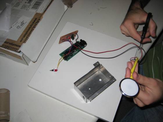
Our hardware consisted of a fairly small circuit on a solder board, a microcontroller circuit, and a microphone inside a stethoscope. We packaged all of this into a small aluminum box which we made from sheet metal. Holes for connecters and switches were then cut out. The microphone is attached to standoffs which "push" the stethoscope on the surface which the box is placed on. Figure 2 below shows all our hardware and an image of our complete packaged project.

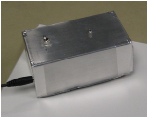
Figure 2: Hardware and final packaged project.
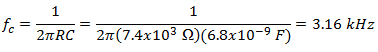
Figure 3 shows the circuit we built onto the solder board. This circuit is divided in four stages and is used to produce a reliable and sensitive acoustic waveform. First, an electret microphone was put in series with a 2k? resistor. The microphone can be modeled as a variable resistor dependant on sound and pressure waves. Thus, the voltage drop across this resistor will depend on the sound the microphone is hearing. After the input sound at the microphone has been transformed to a fluctuating analog voltage, the signal is passed through a high-pass filter which filters out sound lower than 3 kHz. This cutoff frequency was chosen to filter out common ambient sounds and because the sound of a fingernail scratching a surface is above 3 kHz. The capacitor of this filter was chosen to be 6.8 nF and the resistor was 7.4 k? to achieve a cutoff frequency of approximately 3 kHz:
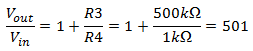
The third stage is used to amplify the signal using an LM358 opamp in a non-inverting configuration. We experimented with resister values to find an optimal gain for our application. We needed a high enough gain so that scratches are easily picked up and recognized, but too high of a gain would cause the signal to saturate. We decided on using a gain of about 500:
The final stage of our analog circuit is an envelope detector which takes a high-frequency signal as input, and outputs the "envelope" of the original signal. To determine the resister and capacitor values, we experimented to find the optimal bandwidth. The values we chose gave us a bandwidth of about 1.7 Hz:


Figure 3: Hardware Circuit
Software Design
Our software has three main pieces of code, signal capture, feature extraction, and gesture interpretation. After each gesture is filtered in analog, we extract certain features from the signal from the analog-to-digital converter (ADC). Once the gesture is finished, we take the features extracted from the signal and attempt to map the features to a gesture.
While the signal capture and feature extraction are executed roughly every 0.5 ms, gesture interpretation only occurs when the software believes the gesture is finished. The gesture is considered finished if the voltage to the ADC is below a certain threshold for 360 ms.
Although capture and extraction, and gesture interpretation are linked together by the timeout variable, they essentially run in parallel.
The final piece of our software runs on a PC, which maps the gesture that the microcontroller has interpreted to an action on the PC. The microcontroller talks to the PC via RS-232 communications.

Figure 4: High level software architecture on the microcontroller.
Signal Capture
Signal capture grabs the ADC values from port A0 and calculates four different moving averages: moving, avg, upper, and lower. moving is a short 60 point moving average that attempts to smooth out small variations in the signal such as the envelope detector's RC ripple. avg gives the moving average of the past 200 points. From avg, upper and lower are calculated; upper is simply 1.2 times avg while lower is simply 0.8 times avg. upper and lower are used as hysteresis limits for peak detection.
Feature Extraction
Because our greatest concern was the memory limits and processing power of the microcontroller, we wrote feature extraction to hold as little past data points as possible. Rather than storing the entire signal in memory then extracting features and interpreting gestures after the gesture is finished, we extract features in real time with very little past data points. The past data points, 96 ms worth of data, are only used in the moving average calculations.
Our next issue of importance was an amplitude independent peak detection algorithm. Our entire idea for gesture interpretation depended on the ability to detect intended local minimums and maximums regardless of amplitude. Our efforts were further hampered by small noise peaks.
Our biggest software breakthrough was the amplitude independent peak detection algorithm that required very little memory and processing power. The final implementation employed the use of moving averages and hysteresis. A peak is detected when moving becomes greater than upper and THRESHOLD but only if state isUpper is 0. isUpper becomes reset when moving becomes smaller than lower. This hysteresis removes noise spikes by preventing multiple but small crossings of upper. This algorithm only required the past 96 ms worth of data for moving averages rather than the entire gesture signal, drastically reducing the memory requirements needed.
All other extracted features are based on the hysteresis of moving between upper and lower. Each peakWidth is the number of ticks between moving becoming greater than upper and moving becoming less than lower. Each valleyWidth is the number of ticks between moving becoming smaller than lower and moving becoming greater than upper. Each peakHeight is the greatest value between when moving becomes greater than upper and when moving becomes less than lower. Each peakSlope is the number of ticks between moving becoming greater than upper and when peakHeight is reached. signalWidth is the number of ticks between moving becoming greater than THRESHOLD and the final gesture timeout.

Figure 5: Captured double tap data from the microcontroller. Black line is moving, blue is upper, green is avg, yellow is lower.
Gesture Interpretation
Gesture interpretation for all gestures except circles is done after the gesture is finished. Gestures are assumed to be finished if the voltage level falls below THRESHOLD for more than 360 ms. This timeout process is accomplished in extract(). As long as moving is greater than THRESHOLD, time2 is constantly reset.
Gesture interpretation for all gestures except circles is based on a simple decision tree that checks if extracted features fall within hard coded maximum and minimums. If a gesture's features do fall within the limits of a particular gesture, the software assumes that gesture was drawn.
Circles are slightly different because feedback is given to the user as the gesture is being done. Once four or more peaks are detected, every peak afterwards is assumed to be one revolution.
As soon as a gesture is successfully interpreted, a single character is sent to the PC via RS-232. This is done as a simple blocking fprintf() statement because gestures are not going to be done in rapid succession and blocking is acceptable.
PC Software
Once the microcontroller tells the PC what gesture has been scratched, the PC takes one of four different actions: toggle mute, quick launch one of three different programs, change volume up, and change volume down.
The program is written in C# and reads the serial port that the microcontroller writes to. Depending on the character written by the microcontroller, a different action is taken.
- Results
of the Design
We tested our system by recruiting friends to help test. A small pamphlet was given to them about how to use the system. We then let them play with the system for about 10 minutes. Afterwards, we asked them to perform a series of gestures and recorded their accuracies.
We managed to achieve almost 90% accuracy for all our gestures except for 3's, which had significantly less accuracy at 68%. While we had not reproduced the same accuracy as Chris Harrison's reported accuracy of 95%, most of our gestures were approaching that level of accuracy.
Although our gestures were not 95% accurate, we are still very happy with our
results. We believe that with further testing and tweaking, we can achieve 95%
accuracy. Furthermore, as a person gets more used to the gesture style of our
system, accuracy levels will increase.

Figure 6: Accuracy of our gestures.
Project Conclusions
Our initial idea of using two microphones for time-of-arrival differences to measure position had to be scrapped because of the inability to detect local maximums and minimums independently of amplitude in analog hardware. This hardware problem forced us to employ software techniques for peak detection. However, because of memory limitations, time-of-arrival measurements in software were deemed infeasible.
Gesture interpretation accuracy is very good for simple gestures (double tap, triple tap, single lines) while accuracy for more complex gestures (two's and three's) leave something to be desired. However, overall we are happy with the accuracy of our system.
Foreseeable future improvements to our project include training the gesture interpreter to learn the gestures of a user and adaptive gain control. Currently, due to time constraints, we force the user to adapt to the gesture interpreter and simply calibrate the system for one particular surface.
Because of the extremely low memory and processor utilization, we can port our project to even cheaper and lower powered microcontrollers. Very low production costs coupled with its ability to interface with most surfaces, thousands of applications are possible, ranging from furniture with built in remote controls to home automation and control.
Applicable Standards
The only applicable standard in our design was the RS-232 communications with the PC. Since the universal asynchronous receiver/transmitter (UART) code was already written for us and used in previous lab and works well, we assume that the code adheres to RS-232 standards very strictly.
Intellectual Property Considerations
While the idea of a scratch based user input system is based on Chris Harrison's work, the actual design and implementation of our project was independently developed by us. From Harrison's work, we borrowed the use of a microphone attached to a stethoscope for sound capture, the idea that certain simple gestures have unique acoustic signatures, and the gestures double tap, triple tap, line, and circles. The analog hardware, real time feature extraction algorithms, and moving average hysteresis based amplitude independent peak detection algorithms were developed from scratch.
We did use code from the public domain for the PC software. We combined example code for reading serial ports and performing certain actions on the PC to obtain our final version of the software.
Because there are many acoustic processing and recognition patents and gesture recognition patents, we highly doubt there are patent opportunities for our entire system. However, our amplitude independent hysteresis based peak detector may be novel enough for a patent.
Like patents, we doubt there are publishing opportunities because our work is based on Harrison's paper "Inexpensive, Unpowered and Mobile finger Input Surfaces". However, some of our algorithms may be original enough for publishing opportunities.
Legal and Ethical Considerations
Throughout every phase of the development of our project, we followed IEEE's Code of Ethics rigorously. Every non-original idea was credited to its original author. We also always conducted ourselves cordially and professionally, even when there are disagreements with overall project direction or smaller technical decisions. While no safety problems were brought to our attention, we would have immediately taken action upon discovering of safety concerns. The one possible health concern that might have been an issue, the wearing down of the fingernails after frequent and continuous use of our system, was disclosed. We believed that we have the competency to develop this project and based on our final results, we still believe so. Last, our intentions were always in the best interests of individuals, the public, and the environment. Since we were competent and our intentions were purely good, we followed the spirit as well as the letter of IEEE's Code of Ethics
#include <inttypes.h>
#include <avr/io.h>
#include <avr/interrupt.h>
#include <stdio.h>
#include "uart.h"
FILE uart_str = FDEV_SETUP_STREAM(uart_
#define t1 2
#define t2 1500
#define t2Circle 3000
#define t3 750
#define t4 12000
#define AVG_LEN 200
#define MOVING_LEN 60
#define THRESHOLD 400
#define PAST_LEN 6
#define LOG_LEN 900
volatile char time1;
volatile int time2, time3, time4;
int mic[AVG_LEN + 1], moving = 0, avg = 0, upper =
0, lower = 0,
peakWidth[PAST_LEN], valleyWidth[PAST_LEN],
peakSlope[PAST_LEN],
peakHeight[PAST_LEN], peakCount = 0, index = 0,
begin = 0, isUpper = 0,
signalWidth = 0, tPeakWidth = 0, tValleyWidth = 0,
tSignalWidth = 0,
tPeakSlope = 0, k = 0;
char circleMode = 0, tapCircle = 0;
ISR (TIMER0_COMPA_vect) {
if (time1 > 0) time1--;
if (time2 > 0) time2--;
if (time3 > 0) time3--;
if (time4 > 0) time4--;
}
void capture() {
// Captures the ADC value and calculates two
different moving averages.
// Moving is a moving average of the past 60 data
points. Moving simply
// smooths out the sometimes erratic signal from the
analog filter.
// Avg is a moving average of the past 200 data
points. Avg is used to
// calculate the hysteresis values upper and lower.
mic[index] = ADCH;
ADCSRA |= (1 << ADSC);
if (index >= MOVING_LEN)
moving = moving + (mic[index] * 10 / MOVING_LEN) -
(mic[index - MOVING_LEN] * 10 / MOVING_LEN);
else
moving = moving + (mic[index] * 10 / MOVING_LEN) -
(mic[AVG_LEN + 1 - MOVING_LEN + index] * 10 / MOVING_LEN);
if (index == AVG_LEN)
avg = avg + (mic[AVG_LEN] * 10 / AVG_LEN) - (mic[0]
* 10 / AVG_LEN);
else
avg = avg + (mic[index] * 10 / AVG_LEN) - (mic[index
+ 1] * 10 / AVG_LEN);
upper = 12 * avg / 10;
lower = 8 * avg / 10;
}
void extract() {
// Extracts features from the incoming signal, such
as peak heights, peak
// slope, peak width, valley width, signal width,
and peak count. This is
// done without holding any past data points. Past
data points are only
// kept for moving averages.
//
// Peaks count is amplitude independent. This is
done by hysteresis of
// moving. Whenever moving is greater than upper, a
peak is counted only if
// moving has been smaller than lower previously
isUpper is used to keep
// the hysteresis state.
if (moving > THRESHOLD) {
if (circleMode) time2 = t2Circle;
else time2 = t2;
if (!isUpper && moving > upper) {
isUpper = 1;
if (peakCount == 0) tSignalWidth = 0;
else valleyWidth[(peakCount - 1) % PAST_LEN] =
tValleyWidth;
peakCount++;
tPeakWidth = 0;
tPeakSlope = 0;
}
}
if (isUpper) {
if (peakHeight[(peakCount - 1) % PAST_LEN] <
moving) {
peakHeight[(
peakSlope[(
}
if (moving < lower) {
isUpper = 0;
tValleyWidth = 0;
peakWidth[(
}
}
}
void selector() {
// Attempts to map the attributes extracted from the
signal to a gesture.
int tempWDiff, tempHDiff, antiTap = 0;
signalWidth = tSignalWidth;
// Often times when starting a gesture, the initial
finger placement creates
// an unwanted tap with RC decay. The following
anti-tap filters out most
// unwanted intial taps.
if (peakCount > 1 && peakWidth[0] <
200 && peakWidth[1] > 185) {
antiTap = 1;
peakCount--;
}
if (peakCount == 1) {
if (peakWidth[0 + antiTap] < 200) {
tapCircle = 1;
time4 = t4;
}
else if (peakWidth[0 + antiTap] > 230 &&
peakWidth[0 + antiTap] < 1000)
fprintf(
}
else if (peakCount == 2) {
tempHDiff = peakHeight[0] - peakHeight[1];
if (tempHDiff < 0) tempHDiff = -tempHDiff;
if (tempHDiff < peakHeight[0] / 10 &&
peakWidth[0] < 200 && peakWidth[1] < 185)
fprintf(
else if (peakWidth[0 + antiTap] > 220 &&
peakWidth[1 + antiTap] < 300 && valleyWidth[0 + antiTap] > 250
&& peakSlope[1 + antiTap] < 300)
fprintf(
else if (peakWidth[0 + antiTap] > 220 &&
peakWidth[1 + antiTap] > 240 && valleyWidth[0 + antiTap] > 250)
fprintf(
}
else if (peakCount == 3) {
tempHDiff = peakHeight[0 + antiTap] - peakHeight[1 +
antiTap];
if (tempHDiff < 0) tempHDiff = -tempHDiff;
if (tempHDiff < peakHeight[0] / 10 &&
peakWidth[0] < 200 && peakWidth[1] < 185 && peakWidth[2]
< 185)
fprintf(
else if (tempHDiff > (2 * peakHeight[0 + antiTap]
/ 5) && peakWidth[0 + antiTap] > 220 && peakWidth[2 +
antiTap] > 240) {
tempHDiff = peakHeight[2 + antiTap] - peakHeight[1 +
antiTap];
if (tempHDiff < 0) tempHDiff = -tempHDiff;
if (tempHDiff > (2 * peakHeight[2 + antiTap] /
5))
fprint
}
}
}
void reset() {
// Resets the all signal characteristic variables
for the next
// gesture input.
for (int i = 0; i < PAST_LEN; i++) {
peakHeight[i] = 0;
peakWidth[i] = 0;
peakSlope[i] = 0;
valleyWidth[i] = 0;
}
circleMode = 0;
peakCount = 0;
isUpper = 0;
}
int main() {
// Resets variables for the initial gesture.
int rPeakCount = 0;
for (int i = 0; i < AVG_LEN; i++) mic[i] = 0;
time1 = 0;
reset();
// Starts Timer0 and Timer0 interrupts for task
scheduling.
TCCR0A = (1 << WGM01);
TCCR0B = 3;
OCR0A = 60;
TIMSK0 = (1 << OCIE0A);
// Readies the ADC.
ADMUX = (1 << REFS1) | (1 << REFS0) |
(1<<ADLAR);
ADCSRA = ((1 << ADEN) | (1 << ADSC)) +
7;
// Readies the UART.
uart_init();
stdout = stdin = stderr = &uart_str;
fprintf(stdout, "UART Initialized\n");
sei();
while (1) {
// Time1 executes approximately every 0.5 ms. Time1
captures the ADC
// signal and extracts characteristics from the
signal.
if (time1 == 0) {
capture();
extract();
if (tPeakWidth < 10000) tPeakWidth++;
if (tSignalWidth < 10000) tSignalWidth++;
if (tValleyWidth < 10000) tValleyWidth++;
if (tPeakSlope < 10000) tPeakSlope++;
index++;
index = index % (AVG_LEN + 1);
time1 = t1;
}
// Time4 executes approximately 2.88 s after a
circle or tap is
// detected. Time4 is a timeout counter for tap
circle. Time4 is only
// reset when a circle gesture is detected or when
there is a
// singular tap.
if (time4 == 0 && tapCircle == 1)
tapCircle = 0;
// Time3 executes approximately every 180 ms. Time3
looks for circle
// gestures. Circle gestures are detected in real
time rather than after
// the gesture is finished.
if (time3 == 0 && peakCount > 3) {
if (peakWidth[(peakCount - 1) % PAST_LEN] > 240)
{
circle
time4 = t4;
if (rPeakCount < peakCount) {
}
}
rPeakCount = peakCount;
time3 = t3;
}
// Time2 executes approximately 360 ms after a
gesture is done. Time2
// is a timeout counter for all gestures except for
circles. After
// a gesture falls below the threshold value, the software
waits 360 ms
// to make sure the gesture is finished and not just
temporarily below
// the threshold.
if (time2 == 0 && peakCount > 0
&& peakWidth[0] > 0) {
selector();
reset();
}
}
}
using System;
using System.Collections.Generic;
using System.ComponentModel;
using System.Data;
using System.Drawing;
using System.Linq;
using System.Text;
using System.Windows.Forms;
using System.Diagnostics;
using System.Runtime.
using System.IO.Ports;
using System.Media;
namespace WindowsFormsApplication1
{
public delegate void SimpleD();
public partial class Form1 : Form
{
public Form1()
{
InitializeComponent();
}
private void Form1_Load(object sender, EventArgs e)
{
initPort();
}
private void initPort()
{
port.BaudRate = 9600;
port.PortName = "COM1";
port.DataBits = 8;
port.Parity = Parity.None;
port.StopBits = StopBits.One;
port.DataReceived += new
SerialDataReceivedEventHandler
}
SerialPort port = new SerialPort();
string str;
private const int APPCOMMAND_VOLUME_MUTE = 0x80000;
private const int APPCOMMAND_VOLUME_UP = 0xA0000;
private const int APPCOMMAND_VOLUME_DOWN = 0x90000;
//private const int APPCOMMAND_MEDIA_NEXTTRACK =
0xB0000;
//private const int APPCOMMAND_MEDIA_PREVIOUSTRACK =
0xC0000;
//private const int APPCOMMAND_MEDIA_STOP = 0xD0000;
//private const int APPCOMMAND_MEDIA_PLAY = 0x2E000;
private const int WM_APPCOMMAND = 0x319;
[DllImport("user32.dll")]
public static extern IntPtr SendMessageW(IntPtr hWnd,
int Msg, IntPtr wParam, IntPtr lParam);
public void comInterrupt(object sender,
SerialDataReceivedEventArgs e)
{
//read data waiting in the buffer
str = port.ReadExisting();
//display the data to the user
rtbDisplay.Invoke(new EventHandler(delegate
{
rtbDisplay.SelectedText = string.Empty;
rtbDisplay.AppendText(str);
rtbDisplay.ScrollToCaret();
}));
SimpleD d;
switch (str)
{
case "D": d = new SimpleD(toggleMute);
this.Invoke(d);
break;
case "1": d = new SimpleD(launch1);
this.Invoke(d);
break;
case "2": d = new SimpleD(launch2);
this.Invoke(d);
break;
case "3": d = new SimpleD(launch3);
this.Invoke(d);
break;
case "X": d = new SimpleD(close);
this.Invoke(d);
break;
case "W": d = new SimpleD(volDown);
this.Invoke(d);
break;
case "C": d = new SimpleD(volUp);
this.Invoke(d);
break;
}
}
private void toggleMute()
{
SendMessageW(this.Handle, WM_APPCOMMAND,
this.Handle, (IntPtr)APPCOMMAND_VOLUME_
}
private void close()
{
SendKeys.Send("%({F4})");
}
private void launch1()
{
Process p = new Process();
p.StartInfo.WindowStyle = ProcessWindowStyle.Normal;
p.StartInfo.FileName =
@"C:\Windows\System32\calc.
p.Start();
}
private void launch2()
{
Process p = new Process();
p.StartInfo.WindowStyle = ProcessWindowStyle.Normal;
p.StartInfo.FileName = @"C:\Windows\winsxs\x86_
p.Start();
}
private void launch3()
{
Process p = new Process();
p.StartInfo.WindowStyle = ProcessWindowStyle.Normal;
p.StartInfo.FileName = @"C:\Program
Files\Microsoft Office\Office12\winword.exe";
p.Start();
}
// Volume Up
private void volUp()
{
SendMessageW(this.Handle, WM_APPCOMMAND,
this.Handle, (IntPtr)APPCOMMAND_VOLUME_UP);
}
// Volume Down
private void volDown()
{
SendMessageW(this.Handle, WM_APPCOMMAND,
this.Handle, (IntPtr)APPCOMMAND_VOLUME_
}
private void button1_Click(object sender, EventArgs
e)
{
port.PortName = comboBox1.Text;
port.Open();
}
}
}
- Hardware Schematic
|
Part Description |
Quantity |
Cost |
|
Electret Microphone |
1 |
$1.00 |
|
Stethoscope |
1 |
$8.00 |
|
ATmega644 Microcontroller |
1 |
Sampled |
|
Max233 CPP |
1 |
Sampled |
|
Solder Board |
1 |
$1.00 |
|
Analog Circuit Components |
N/A |
Free |
|
RS232 Connector for Custom PCB |
1 |
$1.00 |
|
LM358 |
1 |
$0.50 |
|
Header sockets |
2 |
$3.00 |
|
Power Supply |
1 |
Salvaged |
|
Aluminum for Box |
N/A |
Salvaged |
|
Assorted Hardware (screws,
standoffs, etc.) |
N/A |
Salvaged |
|
Total |
$14.50 |
John
Wang:
Software design,
website, testing
Gary Halajian:
Hardware design, box machining, testing

To create the "double tap" gesture, simply double tap the surface with your fingernail perpendicular to the surface. The two taps should be fairly quick (about 0.5 seconds apart). The taps should also be of approximately the same intensity or loudness. Using one finger for both taps helps to make these taps equal. It should also be noted that this gesture can be imitated by two quick claps of your hands. This gesture will be used to toggle mute on or off.
The waveform shows the acoustic signature that you should replicate. Notice the sharp increasing edges which correspond to the start of each tap, and the RC decay after each tap.

The "triple tap" gesture is just like "double tap" except that there is one more tap which means one more peak in the waveform. This will be used for closing the active window or application just like the Alt-F4 keyboard shortcut.

The "1" gesture is also very simple. Swipe your finger in a straight line again using the top of your fingernail. The direction of the swipe should be perpendicular to the edge of your fingernail and you must swipe towards your body. Using your index finger from top to bottom works well. This gesture will quick launch the first application.
The waveform shows a very small peak from when you initially touch the surface, followed by a fairly sharp rise when you begin the swipe. This main peak then decays throughout the swipe since you naturally reduce the pressure on the surface while swiping. This gesture is "longer" than a tap.

The "2" gesture is a little different than you might except. First, begin the motion for the number 2 with your fingernail starting from the top but do not complete the base of the number 2. Instead, simply tap somewhere on the surface after the first motion. This tap should be done within about 0.5 seconds after completing the first motion. This gesture will quick launch another application.
The waveform for the first motion looks similar to the "1" gesture with a rising then decreasing peak. The next peak with the sharp rise and RC decay corresponds to the tap.

The "3" gesture is fairly straightforward. Create a number 3 starting from the top while two fairly equal bumps. The bumps should be well rounded. This gesture will quick launch a third application.
You can clearly see the large equal bumps from the waveform. The pattern resembles a double tap but is much more spread out (larger base width) and has slower rising edges.

The "CCW circle" gesture is also straightforward. Begin to make a counterclockwise circle with your fingernail starting at any point. The exact size of the circle is not critical but it should be fairly large. A diameter of about 3 to 4 inches works well. We will use this gesture for decreasing the volume of a PC. The first few revolutions will be used to recognize the pattern and enter circle mode. This is to prevent any interface with other gestures. After this startup period, each revolution will decrease the volume by one notch.
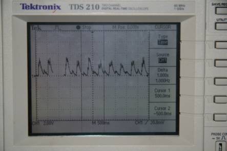
The waveform shows a sequence of large peaks followed by small peaks. This is formed from the natural acceleration and deceleration of your finger throughout different parts of the circle.

The "CW circle" gesture is the similar to the "CCW circle" except that you need to tap on the surface before you begin to create the clockwise circles. You need to wait approximately 1 second after the initial tap before you before the clockwise circle motion. This gesture will be used to increase the volume of a PC. The initial tap is needed to distinguish from a "CCW circle," and to avoid a possible situation where the volume may become painfully loud due to random noise. Once again, the first few revolutions will be used to recognize the pattern and enter circle mode. After this startup period, each revolution will increase the volume by one notch.
The waveform for a clockwise circle is essentially the same as that of a counterclockwise circle, which is one reason for the initial tap. Thus, this waveform will start with a quick sharp peak as seen previously, then a 1 second pause, followed by a sequence of large and small peaks which corresponds to circular motion.
- Harrison,
Chris and Hudson, Scott E. Scratch Input: Creating Large, Inexpensive,
Unpowered and Mobile finger Input Surfaces. In Proceedings of the 21st
Annual ACM Symposium on User interface Software and Technology. UIST
'08. ACM, New York, NY, 205-208.
- LM358
Datasheet
- Jameco
Part #136574 Datasheet
- ECE476
Dueling Banjo's
- ATMega644
Datasheet
- C#
Serial Port Reading