Multisensor Picosatellite with Unidirectional Data Transmission
Jovan Begovic (jb433) and Elliot Kulakow (eak56)
Introduction
For our final project we built a prototype of a circuit intended for a picosatellite that measures temperature and acceleration, sending the information wirelessly back to a base station receiver.
The N-Prize is an amateur rocketry competition challenging groups to launch a very small (10g-20g) satellite into orbit for less than $2000, and track it over 9 orbits. While modern large satellites require hundreds of people working together to build and are incredibly complicated, the N-Prize offers the opportunity for something dramatically different- a very small satellite, which can be built by one or two people. At its core, the only electrical components required are the power source and a transmitter. The only requirement for the prize is that the satellite can be tracked; like Sputnik, our satellite circuit prototype primarily consists of a transmitter beacon, and makes further use of the microcontroller to adequately sample the two onboard sensors.
High Level Design
Rationale
There's nothing quite like space exploration to get the creative juices of an engineer flowing, and what better outlet than a final design project? The N-Prize fits this mold pretty well, it's an amateur rocketry competition with an emphasis on low cost and easily accessible components. If a couple of college students can build a working satellite in a month, then so can anyone else. A 20 gram mass is sufficient to fit more than one integrated circuit along with connectors and a small power source. Furthermore, the task of building such a device is very feasible; all you need is an RF transmitter and a power source. Of course, such a seemingly simple task has many unexpected challenges to work out.
Logical Structure
Our satellite's core feature is the RF transmission system and protocol. This is the most important for a simple reason: if you can't hear (or see) your satellite, you can't prove that it's there, and it is of no use to you. Initially, we wanted to use our own protocol that would follow an existing communications standard such as HDLC, which is good for small packets and includes a CRC check code, but since there was already a convenient protocol written for the transmitter we had the easiest access to, the RCT-433, we elected to use it instead. Without Meghan Desai's Wireless Protocol it is unlikely we would have succeeded in accomplishing the amount we did. As is, we integrated the existing functions, updated for the Mega-644 chip and GCC compiler, with an analog multiplexer to be able to read more than one sensor. We extended the protocol by providing an 8 bit cyclic redundancy check (CRC) code for error detection. On the receiver side, the frames are decoded using the aforementioned protocol, checked with the CRC, and output to a workstation using the internal UART on the microcontroller.
Hardware/Software Tradeoffs
Our project is all about trading hardware capabilities on a large satellite for an inferior but still sufficient solution on a small one. For one, any respectable large satellite would implement most of their electronics using multiple FPGAs or ASICs to give the engineers maximum control over the exact workings of the vehicle. Using only a single microcontroller to do both data input from sensors and data transmission turned out to be much more challenging than was expected, as the ADC operation interfered with the UART and prevented clean transmission when operated asynchronously. This was the most significant tradeoff we had to make, between using two microcontrollers to allow for easy input of analog values and figuring out how to run the UART and ADC synchronously. Since we had a cushion in our budget, we elected to go with two chips as this greatly simplified the code required.
Software and Hardware Design
Software
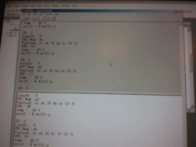
We approached the software design with simplicity and scalability in mind. Our design is essentially a basic telemetry system suitable for updating the user as to the status of the relevant sensors on their device. We found an excellent open source program for calculating CRCs written by Michael Barr available on netrino.com. We modified this code for a CRC-8 and included it on both the transmitter and receiver side. The ground station output is simply formatted text on a serial communications line hooked up to a computer. In a real ground station, the microcontroller would do no formatting and simply send a parsed binary stream, but as we had no software for analyzing this data and no need for it, we decided to do all our formatting before transmission.
On the isolated transmitting system we tried to utilize the hardware features of the 644 as much as possible so as to avoid messy code. Unfortunately, some of these features have idiosyncrasies that are more complicated than we were expecting and so maximum use of hardware features was bypassed in exchange for a quicker design. Specific issues we ran into include being able to reconfigure the internal UART on the fly to handle different baud rates of data, and running both the UART and ADC on the same chip in close timing. The former of these issues could be resolved, but the latter proved far more challenging than expected, and was bypassed in exchange for a hardware solution. A complete program listing follows:
Ground and Satellite
crc.c
//This file was written by Michael Barr and modified by us to perform CRC-8.
void crcInit(void);
This function initializes the look up table used in the crcFast function, allowing the calculations to be easily performed in real time. The generating polynomial is 0x07 and the initial remainder is 0xFF, in order to avoid issues with data that is all zero.
crc crcSlow(unsigned char const message[], int nBytes);
This function explicitly calculates the modulo-2 division required for a CRC and as such is much slower than the following one.
crc crcFast(unsigned char const message[], int nBytes);
This function uses the LUT generated by calling crcInit() to quickly find the CRC of the provided message.
txrx.c
//Written by Meghan Desai, modified for use with Mega-644 and GCC compiler.
//Only modified functions are listed.
void txrx_init(int tx, int rx, int baud_num, char led);
This function initializes either the transmitter, receiver, or both for the specified baud rate number as calculated per UART register specification. It has been modified so as to not actually start the transmitter when called, thereby saving power.
ISR (USART0_UDRE_vect)
The transmit ISR, this interrupt routine has been modified so as to shut down the transmitter once the last byte has been successfully sent over the UART.
void encode(void);
This important function encodes the data that has been loaded into the transmit buffer into the format required for successful RF transmission. It has been modified to read the code bytes from program memory, instead of simply from an array. This makes no functional difference and is probably unnecessary.
void tx_me(char tx_data[], int length, int id);
This function has been extensively modified to append a CRC to the data stream being sent, and correctly give the new length. After completing this task it then starts up the transmit ISR manually, as opposed to continual operation in the previous design.
Ground Station
Ground.c:
void initialize(void);
This function configures the ground station by initializing the uart, sending a startup message, configuring the LED port, starting a timer, initializing the crc, and finally initializing the uart (note that this overwrites the previous uart initialization) to receive the first frame.
ISR (TIMER0_COMPA_vect)
This ISR increments a 1ms timer. Currently this timer is not used for anything.
int main()
The main function decodes a complete frame into readable data, parses this data into a string for easy access, calculates the CRC check code for the received data and compares it to the expected value, briefly reinitializes the uart for transmission at 9600 baud, transmits a formatted string containing all important frame information, and reinitializes the receiver to catch the next frame.
Satellite
Satellite.c:
void init(void);
This function initializes the satellite transmitter unit. It configures ports A and C as inputs, port D as an output, timer0 for a 1ms timebase, the uart for 2000 baud transmission, and the crc.
void get_data(char count);
This function loads the data buffer with the packet count, 0xece476, a 16 bit time in milliseconds, and the contents of port A (temperature) and port C (acceleration).
ISR (TIMER0_COMPA_vect)
This ISR increments a 16 bit system time and decrements the timer used to trigger frames.
int main()
Every 100ms, the main function loads a frame into the data buffer, increments the packet count, transmits a frame, and toggles the led.
ADC
adc_tester.c:
void initialize(void);
This function initializes the ADC unit with ports B, C, and D as outputs. It configures timer 0 and the ADC, and starts the first conversion.
void task1(void);
This function calls the correct ADC read function and updates the corresponding port based on the value of the multiplexer selection variable. It updates the mux selection, on port D, and starts the next conversion.
void getTemp(void);
This function loads ADCH into the temperature variable and performs a brief conversion to degrees fahrenheit.
void getAccel(void);
This function loads ADCH into the acceleration variable, but does not perform a conversion.
ISR (TIMER0_COMPA_vect)
This function decrements the timer that controls when ADC reads are performed.
int main(void)
This function calls task1 every 10ms, updating the values output on ports B and C.
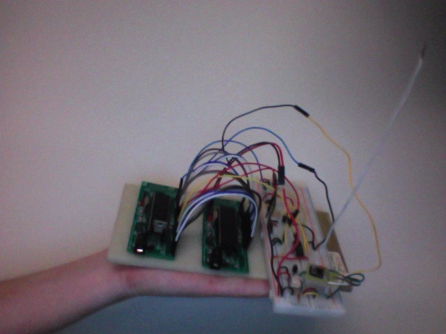
Hardware
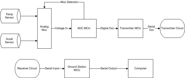
The hardware consists of the sensors multiplexed through to an MCU, which then sends the processed data in packets via a wireless link through a transmitter; the receiver on the other end of the link then feeds another MCU the packets, and the data is formatted and displayed to the user with the hyperterm interface.
Sensor Logic and Output
The following schematic outlines the structure of the sensor and signal multiplexing circuit:
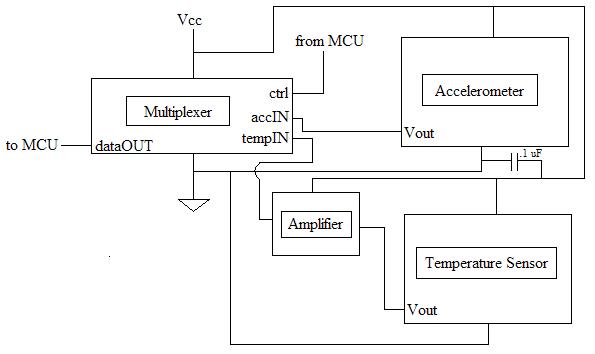
The accelerometer and temperature sensor both feed voltage signals into the analog multiplexer. Since there were only two signals, we only used the lowest bit of the mux selector (mux0) and grounded the others. A low mux0 value let through the temperature signal; a high mux0 value let through the acceleration signal. This signal was toggled between high and low, as described in the software section.
Accelerometer
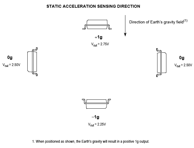
The MMA1220D accelerometer had to be soldered to individual pins to be bread-board compatible; it also required capacitative coupling (.1 uF) to ground to stabilize the signal. The accelerometer was positioned sideways, so that the z-axis (of measurement) is parallel to the ground plane when the bread-board lies flat. A summary of the axes and functionality, taken from the datasheet, is diagrammed below:
Temperature Sensor
The LM34 temperature sensor signal increases 10mV/ degree F. To increase resolution before entering the ADC, the signal was amplified by a factor of two using the LM358 operational amplifier circuit shown below, with R1 = R2 = 10 kOhms:

Transmitter
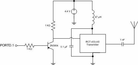
The RCT-433 module transmits data at 433 MHz. The module was soldered to a protoboard designed for its outputs. The antenna wire was 1/4 wavelength of the transmission frequency (18 cm) for optimal performance, and was capacitively coupled to ground to remove noise. The circuit was constructed on a bread-board with minimal wiring clutter to avoid noise.
Receiver
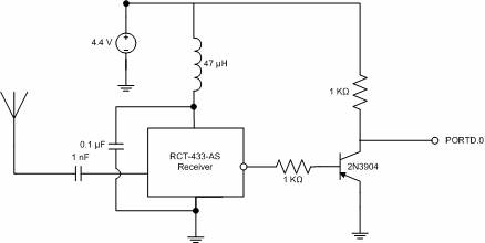
The RCR-433 module receives data at the 433 MHz frequency and converts it back to the original digital signal. We did not use the analog output function of the receiver module. The antenna output pin was bent upward and directly attached to the antenna (also 18 cm of wire) to bypass the noise of the board.
Both circuits were constructed on a bread-board with minimal wire clutter to avoid noise. The circuit designs for both RF modules are taken from Tytus Mak and Daniel DiBernardo's Spring 2007 project:Touch Screen Controlled R/C Car. The only changes made were to increase the power supply to 5V and the inductor choke to 50 uH for convenience.
Hardware Obstacles/Considerations
We were initially using a fried receiver that did not read out a signal; it was especially difficult to figure this out because the oscilloscope only reads up to 60 MHz, so we could not observe a signal directly off the antennas. We were able to borrow a receiver from another group to confirm that our circuit was in order, and we obtained a replacement receiver from Dr. Land.
Additionally, we were having clock period bugs occur when trying to run the ADC simultaneously with the alternating multiplexer control pulse; we attempted to optimize the code, but due to time constraints we were forced to run the ADC conversion on a separate proto-board. Since our initial budget was small, were were able to afford to do this; improved code optimization would significantly lower the budget. An LCD screen that performed the visualizations which the hyperterm interface currently performs would also decrease the budget because we would not have to use an STK500 board.
Results
Software Challenges
By far the largest software challenge faced was also the one that was avoided. Running the ADC and UART transmitter together asynchronously appeared to make the crystal, or some other important oscillator, frequency unstable. When observed on the scope the suspect signal appeared to flicker, as opposed to the expected steady square wave. The macroscopic result of this was that all of the output signals lacked a regular period. Depending on the configuration used, some combination of full width and half width signals combined to make the output square wave, or tx signal, irregular. While this probably would not have affected the ground station terribly much simply due to the time in between transmissions, no one likes an irregular square wave, and better operation was eventually achieved on higher frequencies anyways.
Another software challenge faced was in using the UART to read and write signals of different frequency. This could be easily overcome by changing the baud rate number when the new signal is desired, which is in fact what happens, but a further twist was introduced when it was discovered that fprintf() is non-blocking. Like above, this challenge was somewhat dodged by taking advantage of the large gap between frames to just delay a small number of milliseconds.
Finally, the most significant software challenge, and the only one as of yet unresolved, was that of catching every frame. When we first brought up the link between the two terminals, only the first nibble of bytes without a zero in the most significant four bits was being caught. We were baffled by this, as we had no reason to believe any of our code was incorrectly functioning on the individual bits. After consulting another group using RF, we discovered that this error was due to a compiler discrepancy and with the following small change every nibble could be caught.
//tx_data[(char)(tx_pkt_byte+1)] = pgm_read_byte(code + ((in_data[tx_data_byte]<<4)>>4));
tx_data[(char)(tx_pkt_byte+1)] = pgm_read_byte(code + (in_data[tx_data_byte]&0x0f));
After making this change every nibble was received and the crc check correctly determined if a frame was corrupted. Unfortunately, only around 25% of the packets transmitted were actually successfully received. This may have been due to interference or a poor circuit layout, but we believe that the microcontroller was having difficulty because the frames were spaced a quarter to half second apart. By increasing the frame transmission speed to 10Hz, our catch rate was improved to catch every other packet, with maybe 1% corrupted. There is no reason to believe that the inability to catch every frame is due to anything other than a software bug, but tracking the problem down proved too challenging.
Speed and Accuracy
As of the final revision, our transmitter is running at 10 frames per second, a respectable rate. We can only catch half of the frames sent though, bringing the total frame rate to 5. With a baud rate of 2000, set low to avoid noise, it is impossible to get really good data rates. Our rate of 5/s works out to 10 bytes of sensor data/second, and 40 total bytes of user defined payload per second. While this is low, it is sufficient for a wide variety of telemetry applications. As for accuracy, our temperature measurements are spot on. The lab was in the mid-80s when we finally got our system stable, and we were reminded of this fact ten times per second. The acceleration result is harder to evaluate, but nevertheless gives qualitatively correct data depending on the angle at which the accelerometer is tilted.
Conclusion
Results versus Expectations
When comparing the scope of our actual project to the ambitions of our proposal, we had to scale back in order to finish on time. We set out expecting to be able to construct a complete, independent system suitable for brief exposure to a space environment. We quickly discovered that guaranteeing operation in a space environment would be impossible, and even accurately measuring environmental variables like temperature was very difficult and required expensive components. Furthermore, we discovered that the RF transmitter we had decided to use, while running in an amateur band and therefore good for telemetry and prototyping applications, does not lie in a band approved by the FCC for use on a "space station", thereby nixing the possibility that our design could actually fly as is. We decided instead to pursue a more traditional telemetry system useful perhaps for rocket avionics and ground monitoring. This is also a required part for any successful mission and the system we designed is easily extended to process a larger number of sensors. If we were to start over and do it again, we would definitely start with something less ambitious. Trying to tackle a problem with a large number of constraints was a mistake and led us to become slightly overwhelmed by the initial requirements. A more open-ended project with a defined environment would have allowed a system with more rich features. While our result is still useful, it lacks several of the considerations the initial proposal started out trying to address.
FCC Considerations
Our design fully complies with all FCC communications regulations. It is a prototype operating in the unlicensed 433MHz band and hence has almost no restrictions on its use as long as it is neither sold nor manufactured en mass, which it will not be. Unfortunately, it does not comply with FCC regulations with regards to "space stations". The nearest frequency licensed for such operations lies at 435MHz, close but no cigar. The design would have to use a different frequency were it to be flown. Fortunately, there is no such restriction on rocket telemetry systems and it would be acceptable for use in one.
Intellectual Property Considerations
We used several pieces of open source software in our design. First and foremost, Meghan Desai's Wireless Protocol deserves all credit for making wireless tx and rx simple and fairly painless. We did have to modify his protocol to operate on the new Mega644 controllers and compile with the GCC compiler, as well as adding some extensions to allow for embedded CRC and a more power friendly transmitter. The CRC code used, courtesy of Michael Barr, has been released into the public domain and the disclaimer on the file stating this has been kept intact. The code was modified slightly for use with our polynomial and checksum size. Finally, the receiver and transmitter circuits we used are courtesy of the "Touch Screen Controlled R/C Car" project by Tytus Mak and Daniel DiBernardo.
Ethics
Throughout this project we adhered to the IEEE Code of Ethics. No part of our project could at any time have harmed another student or TA in the lab. We improved upon the existing wireless protocol by porting the code over from mega32 to mega644 format, and discovered subtle corrections to eliminate bugs. We exchanged information with other teams working with RF, fostering a collaborative community that was helpful for debugging and signal testing. All of the data we gathered was genuine; we did not at any point forge results or lie about our project progress. We gave help when asked for it, and asked for help when we needed it, staying open-minded to others' criticisms while being considerate and helpful in our own critiques. All previous deigns that we used were given appropriate credit in the report and listed in the appendix. Lastly, we were respectful of everyone in the lab and careful when maneuvering around other projects in the storage areas.
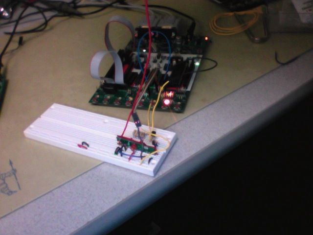
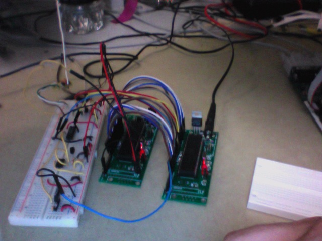
Pictures
Appendix
Appendix 1: The Code
Ground stationTransmitter Unit
ADC unit
Modified CRC open source code
CRC header file
Modified wireless protocol
Wireless protocol header file
Appendix 2: Schematics
Overall hardware designTransmitter circuit
Receiver circuit
Amplifier circuit
Accelerometer function
Appendix 3: Parts List
Part |
Source |
Cost |
| ATmega644 (x1) | Atmel (via Bruce Land) | $8 * 3 = $24 |
| custom PC board (x2) | Bruce Land | $4 * 2 = $8 |
| STK500 (x1) | Atmel (via Bruce Land) | $15 * 1 = $15 |
| 9V DC power source (x2) | Bruce Land | $5 * 2 = $10 |
| RCR-433 receiver (x1) | Radiotronix (via Bruce Land) | $4 * 1 = $4 |
| RCT-433 transmitter (x1) | Radiotronix (via Bruce Land) | $4 * 1 = $4 |
| bread-board (x2) | ECE 3150 Lab | free (got to keep them after the last lab) |
| DIP socket(x2) | Bruce Land | $0.50 * 2 = $1 |
| header pins (x77) | Bruce Land | $0.05 * 80 = $4 |
| MMA1220 accelerometer (x1) | FreeScale (via Bruce Land) | free, sample |
| CD4051 analog multiplexer (x1) | Analog Devices (via Bruce Land) | free, sample |
| LM34 temperature sensor (x1)) | Bruce Land | free, stocked |
| miscellaneous (resistors, capacitors, inductors, wiring) | Bruce Land | free, stocked |
Total = $70.00
Appendix 4: Work Distribution
Jovan Begovic
Transmitter/receiver hardware design and construction
Sensor and multiplexer hardware design and construction
ATmega644 protoboard soldering
Final report
Website construction
Elliot Kulakow
Overall transmitter/receiver programming
Uart interface programming
ADC and multiplexing signal design and programming
Final report
References
Datasheets:
RCR-433-RP
RCT-433-AS
CD-4051-BC
MMA-1220-D
LM-34
LM-358
Borrowed Code/Designs:
Open source program for CRC calculations by Michael Barr
"Touch Screen Controlled R/C Car" by Tytus Mak and Daniel DiBernardo
"WIRELESS TRANSMIT AND RECEIVE (WITxRx)" by Meghan Desai