Software
ECE 4760
Picture Processing & Instruction Generation
When a user loads a picture, our software samples 64x64 linearly spaced points. Unlike an inkjet printer, we cannot control the nozzle on the ink, but instead we are using pen or a pencil. Since we cannot express the coloring, we have crudely estimated RGB to 0 for values lower than 64, 255 for values greater than 192, and 128 for values in between. After sampling, software begins to generate series of the instruction. Before explaining generation of the instruction, we need to discuss limitations of the hardware.
First the precision is a large drawback of our design. For couple of weeks, we tried utilizing the optical mouse as a feedback system. But as due date for the project comes near, we could not open PS/2 communication between optical mouse and MCU; however we have strong sense of what to do.
Precision without a feedback system is very delicate. Although this concern is mentioned in the hardware part, we had implemented two independent wheel operations for movement and one dummy wheel to support the structure. We had reached this conclusion in part because of budget, which limited our purchase of motors, and we wanted a rapid 90 degrees turn rather than a gradual turn. If we were to draw two parallel lines separated by 0.1 inches we need to turn 90 degrees at the end of the first line, move 0.1 inches, and then turn another 90 degrees to start the second line. In order to execute these series of rotation, we rapid turn is more precise than gradual turn.
This delicacy of the hardware made it virtually impossible to make intricate instructions to draw arcs, circles, or a flexible image. Instead we decided to do straight lines approach. In the movie “I, Robot,” there is a scene when a robot sketches its dream and the sketch was drawn using only horizontal lines.
Writing an Instruction Making method was not too hard after all. A general idea is if there is color on consecutive horizontal data points, it will draw a line and if there is no color, then it will just move. When the robot reaches end of the sample (index of either 0 or 63), then it will have series of rotation instructions described above.
GUI
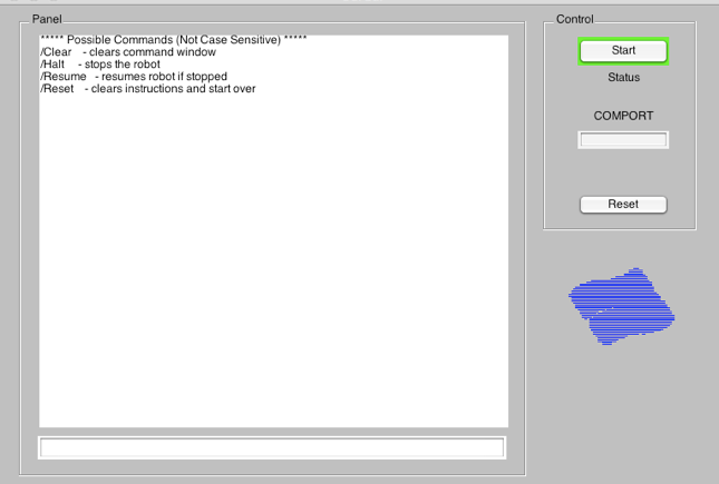
In order to achieve good user interface, we had developed a simple GUI using GUIDE function of the Matlab. A great advantage of using GUI is it is an event-triggered interface. Event-triggered nature of GUI is very useful while Matlab is sending instructions to the MCU.
When the Matlab side of the program is transmitting instructions, it is in a while loop for instruction transmission and transmission validation. Also there is a case when robot’s memory is full (will be discussed below in MCU) when robot cannot take further instruction and Matlab has to wait in a while loop to check status of the robot. In either case, the transmission of the data defers any user intervention.
However like Lab 3, Security System, concurrency is a priority in this system. For instance, even if robot is behaving oddly, a user should be able to easily stop immediately. Also robot must be able to start at any instance when user sends a correct command.
If the User Interface was written in a simple function, above blocking loop may have made the concurrency impossible. But we made our own command window, which is based on callback.
Extra: Instead of user setting COM Port manually, our GUI detects usable port and fills in the box below. However there are times when serial port is locked or need special setting and in that case, the GUI asks user to manually type the name of the port and makes a connection.
MCU
MCU code was written as generic as possible so it can be used for any hardware setting
There are two main softwares: one is Matlab and another in MCU. The software on Matlab part provides a GUI to a user that allows the user to select a picture and execute the robot to draw crude version of the picture. Matlab and MCU communicate using RS232 serial port.
Matlab GUI

void motor(char dir, char motorSel);
Motor function is the most generic function possible. It has a stepper motor driving function whose direction is determined by variable dir. This function is capable of controlling two motors independently using variable motorSel. Also if you examine the code carefully, you can find out that each motor can rotate different number of times.
void rotate(void);
This function consists of series of motor controls. In order to rotate, we first make right motor and left motor move in a different direction. That way, the robots turns and we purposely make it direct slightly to the left. Then robot moves backwards (since we have 64 samples) more than 64 sample distance. It will draw large triangle with very small angle. Then again move right motor and left motor move in a different direction but in an opposite direction than how we rotated in the beginning. In that case, the robot will now face straight again.
Currently the MCU has a role of communication and motor control. Due to the nature of the project, we are not concerned with timing or accuracy of ADC data or anything like that. All the accuracy and timing concern is more of an hardware problem