LEDzeppelin
Ken Colwell, Steve Fuertes
“Musical Expression at your Fingertips…and Beyond”
SKIP TO SECTION:
·
Introduction
·
High-Level Design
·
Software Design
·
Hardware Design
·
Results & Conclusion
·
Appendix 1 – Commented Code
·
Appendix 2 – Schematics
·
Appendix 3 – Cost Breakdown
·
Appendix 4 – Individual Contributions
·
Appendix 5 – References
INTRODUCTION
Wouldn’t
it be cool to be this guy?
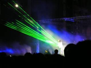
(Jean Michel Garre,
courtesy Wikipedia)
Powerful
laser shining into the audience, playing strings by sweeping your hands across
the beams, rocking out in a room full of fog and fawning girls?
We
thought so. It turns out lasers are
expensive, fog machines aren’t allowed in lab, and fawning girls experience
some sort of force field repelling them away from Phillips Hall and toward
Waiters concerts. But playing strings by
sweeping our hands around was still an option!
We
resolved to build the poor man’s laser harp, using LED emitters shining across
a set of sensors that would notice when we blocked them with our hands. It needed to play tones that sounded sweet
and lovely when we needed it for ballads, and hard-edged and techno when we
were feeling the dirty nerdy groove. It
needed to play several notes at once and listen to a remote control. Most of all, it needed to have a 3.5mm jack
so that someday we could live the dream, playing it in that room next to that
guy, fog machines and all.
HIGH-LEVEL DESIGN
LEDzeppelin
is designed to listen to two input sources, “strings” and remote control
“buttons”, to control and send an 8-bit audio wave through a digital-to-analog
converter to an amplified sound system, as in the diagram below:
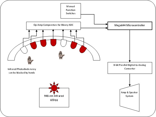
The
microcontroller polls comparators and switches every 50 milliseconds for user input,
generating sound using Direct Digital Synthesis with steps every 128
microseconds; see the “Hardware Design” and “Software Design” sections for
further detail and for tradeoffs between the two.
SOFTWARE DESIGN
The
central question in the LEDzeppelin software design was this:
Given a set of
logical inputs representing “string plucking,” and another representing “chord
buttons,” how could we generate an 8-bit parallel digital signal representing
interesting music?
Direct Digital Synthesis
Direct
Digital Synthesis (DDS) is a general method of producing a repeating waveform
using a digital output. Our first
experience with DDS was a previous lab in this course in which we constructed a
Dual-Tone Multi-Frequency output signal to mimic a telephone dialer; this
concept was extended in several ways in the software for LEDzeppelin.
The
general idea of DDS is to recreate an arbitrary waveform by repeatedly running
the output through a table containing one period of that waveform. The speed at which the output traverses the
table controls the frequency of the output wave, and different frequencies can
each run through the same table independent of each other.
We
programmed our DDS to run through the table by adding an increment value to an 32-bit accumulator
every time our primary timer overflowed.
In order to give the microcontroller time to calculate a complicated
wave output before another interrupt service routing was called, we scaled the
16MHz clock into the 8-bit timer back by a factor 8, so it overflowed every 128
microseconds (about 2000 clock cycles).
Meanwhile, this ISR method allowed the signal to move through the table
at a constant rate, leaving the increment
variable a constant multiple of the tone frequency (see below). Table 1, below, contains the notes we chose
to play, their frequencies, and the corresponding increments. Note that the top increments move through the
full range in about 7-8 cycles, which is more than enough to get frequency and
waveform; in other words, the 7.8kHz switching frequency is high enough above
the maximum output tone frequency of 1.3kHz.
(This also means it wasn’t completely necessary to use a long variable, but it ported well from
our previous code, and it provided the maximum possible table resolution.)


EQ 1: INCREMENT CALCULATION
|
G#
|
415.3
|
228313667
|
|
A
|
440
|
241892640
|
|
B
|
493.9
|
271524488
|
|
C#
|
554.4
|
304784726
|
|
D
|
587.3
|
322871699
|
|
E
|
659.3
|
362454131
|
|
F#
|
740
|
406819440
|
|
G#
|
830.6
|
456627334
|
|
A
|
880
|
483785280
|
|
B
|
987.8
|
543048977
|
|
C#
|
1108.7
|
609514477
|
|
D
|
1174.7
|
645798373
|
|
E
|
1318.5
|
724853286
|
Table 1. Notes, frequencies in
Hertz, and corresponding increment
values.
Making it Interesting
The above system
would allow us to play one note at a time, on one waveform, with one
amplitude. Not good enough for an audience…
not good enough for us.
A real harp
wouldn’t be very interesting if it silenced previous strings when a new string
was played. We needed to make our
instrument polyphonic, so it could play several tones independently. This means cutting up the output space and
devoting one accumulator to each chunk, adding them together for the final
signal.
Since we were
willing to sacrifice only one port to output, we were limited to an 8-bit
signal value; this meant that adding more tones available cut into the amount
of resolution available to each. Also,
we planned to use a signal envelope for each tone, which meant waveforms
couldn’t suffer from poor resolution even when their peak-to-peak amplitude is
low. We chose to make four tones
available at any given time, allowing each a respectable 64 possible values.
Unfortunately,
there are five strings and only four accumulator/increment sets. If there were only four, then each string
could have a dedicated accumulator and increment, and that would be that; adding
a fifth string means that when five strings are played in a row, the
microcontroller must reallocate part of the output space to the newest
string. Since we were already timing
each tone’s age for the signal envelope, we could take the increment from the
oldest tone and give it to the newest one, effectively decoupling
“accumulator[0]” from a particular string and instead assigning it where it was
needed at a particular time. This
required some sleight-of-code to find the oldest string and check if a
particular string is already playing to prevent assigning multiple increments
to a single string.
It might have been
easier to just throw another DAC onto the system or decrease the resolution of
the single-DAC output space, but our code was designed to be modular and
scalable, so we could add more hardware “strings” with only one change in code
(the defined “ALLSTRINGS” constant). If
we had chosen one of the other routes, we would lose either sound quality or
ports on the microcontroller that could be used for more strings. (We could extend our system to have a maximum
of 13 strings if we had the money and time; programming checks showed that the
processor is easily handling the amount of polling it’s currently doing and
could do more.)
Besides multiple
strings, we utilized a benefit of using DDS for sound generation: different waveforms can be introduced with
very little code. We made different
“instruments” for the harp using four common waveforms and a fifth,
experimental form (see below).
Figure 2.
Waveforms available to LEDzeppelin.
The user can use a
button on the remote to select between sine, square, triangle, sawtooth, and
Gaussian waveforms—sine waves for that sweet, angelic sound; triangle waves
with a bit more edge; sawtooth for that electro-lumberjack feel; square waves
for their harsh, digital beauty; and the Gaussian, which is software-tunable
for pluckiness. (Try it, we’re serious.) Each wavetable is calculated during the
software “initialize” phase, so the microcontroller never has to do any
floating-point operations during interrupt service routines.
During testing, we
noticed that our ability to rock out was being restrained by the envelope we
had built: a linear ramp from maximum
amplitude to 0 that took 2.56 seconds, multiplied and normalized inside the
interrupt service routine. The chords
and notes were playing, but the difference in amplitude between 0.0 seconds
after plucking and 0.5 seconds after plucking was nearly inaudible, which meant
rapid-fire plucking of a single note sounded muddy. In response, we updated our envelope. Synthesizer terminology talks about
Attack-Decay-Sustain-Release, but we kept an immediate attack for
responsiveness, decayed very quickly for about 90ms, and released gently over
another 1.5 seconds, which made the instrument much more playable. The envelope can be seen below:
Figure 3. Multiplicative signal
envelope for output signal.
Finally, we recognized at
the outset that the point of a harp is to sound good while strumming; we
decided that each remote control button would reset all the strings to a note
in an arpeggio, rather than a scale, so we could strum all the notes at once
and still sound musical. A “currentNote”
array improved on our previous design to keep the strings from shifting pitch
until they have been re-plucked afterward—of course, if the musician likes the
otherworldly, digital-alien feel of shifting patterns, then he or she can cover
the sensor indefinitely, which the microcontroller interprets as “re-attack,”
and click through the chords. (In our
initial design, we debounced the strings to “sustain” originally but decided we
liked this feature more.)
HARDWARE DESIGN,
IMPLEMENTATION, AND DEBUG
The
hardware used in the making the LEDZeppelin harp can be safely divided into
three subsections: User Sensing, Remote Control, and Digital to Analog
Conversion.
USER
SENSING
In
order to simulate a harp using no strings, it was important to determine when
the user’s hands were placed anywhere along the “spectrum” of possible pitches
available in a method similar to an Autoharp. The method for determining string
“plucking” was based upon sensing shadows caused by interrupting beams of
infrared emissions. The infrared light
chosen as the simulated strings was 940 nm waves, longer than visible to the
human eye.
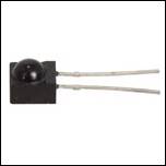
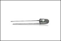
The primary
hardware components involved with sensing the user’s hand movements were Light
Emitting Diodes (LEDs) programmed to emit 940 nm light waves, and infrared
light-sensing silicon photodiodes.
The infrared LEDs
are powered from the system-wide 15V power supply in series with a 250 ohm
resistor as indicated on the circuit diagram in Figure 11 in the appendix. These LEDs shine onto the lower edge of the
curved wooden “spine” of the instrument, creating a plane of waves that come in
contact with the center. The infrared
light plane, or “string plane”, is picked up by an array of photodiodes, each
delivering a voltage differential based upon the intensity of light incident
upon it. The photodiodes have a peak
response of 940 nm, matching the infrared light emitted from our LEDs. Note in Figure 4, the photodiodes are broadly
responsive within 100nm of 940, which means they will see a good deal of
background noise; however, background infrared tends to remain relatively
constant and was subtracted out in hardware.
Furthermore, the photodiodes showed a strong response to a single LED
emitter, scaling approximately linearly with distance and clearly independent
of the noise (see Table 2).
|
Distance from LED (inches)
|
Voltage Differential (Volts)
|
|
3
|
.310
|
|
6
|
.295
|
|
12
|
.280
|
|
24
|
.205
|
|
(LED OFF)
|
.130
|
TABLE 2: Test Values of Photodiode Voltage Differential vs. Distance
from LED in Inches
The concept of the
photodiodes was that if the voltage fell below a certain threshold due to a
hand blocking the light source along a given vector, the “string” associated
with that sensor would be “plucked,” instructing the microcontroller to play
whichever tone is in turn associated with that string. To set up this threshold, The relatively low
voltage differences given by the photodiodes when subjected to the infrared
light of the LEDs is problematic from the standpoint of analog to digital
conversion, given that process-heavy polling would be necessary to track the
changes. A simple amplification of the
sensor voltages by soldering two sensors in series in each sensor location
provides an upgrade in differential by a factor of two. Furthermore, a two stage amplification and
compare circuit is demonstrated in Figure 12 in Appendix 2. Below is a picture of the completed circuitry
for the sensor signal processing:
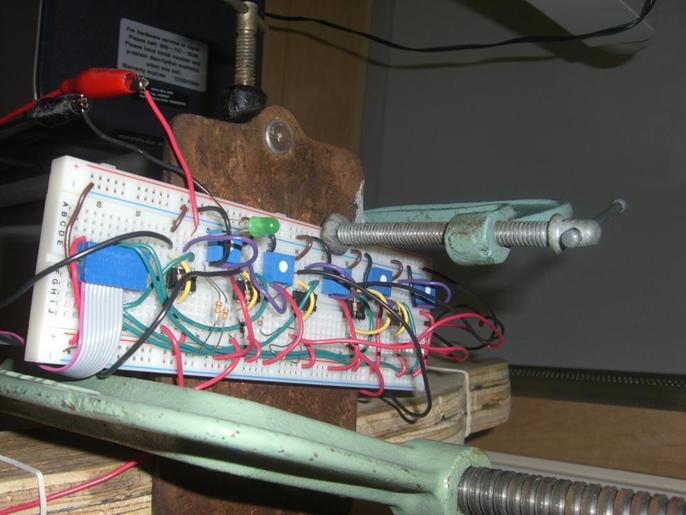
FIGURE 7: SENSOR SIGNAL PROCESSING AND COMPARE CIRCUITRY
This
circuit serves two purposes: The first
amplification magnifies the voltage output of the series connection of
photodiodes. We chose the amplification
factor to provide a gain of 8, magnifying the voltage differential to be about
1.5 volts. This larger differential
value allowed for a simple comparator to return logic HI or LO, indicating
whether the sensor was covered with a much higher confidence than before with
the smaller voltage swing of just .280 V.
This stage was provided by the second pair of resistors set up in a
simple voltage divider circuit. The
secondary voltage of about 2.25 V was provided using a 5V source and a simple
voltage divider.
We found in
laboratory implementation that sunlight from the windows of the lab
occasionally interfered with the photoemitters, adding an ambient voltage to
the photoemitter output to the point where the voltage would rise above a given
comparator voltage target and making it impossible to “pluck” the note. Consequently, a variable comparator voltage
was necessary, so our final design implemented variable resistance trimpots to
adjust to the current light in any environment.
This is somewhat analogous to “tuning” the instrument prior to playing.
The
output of the comparator gave a 3.70 V value for “unplucked strings”, and a
0.00V value for string sensors that sensed an interrupted source. These values for the sensor array were sent
to the microcontroller as digital inputs for plucked strings and tied into the
note playing software algorithm.
Remote Control
Our design
included the capability for the user to modify the sounds being played by the
harp. Besides the original chord built
by the strings of the five sensors, making up the 5 strings of the instrument,
the harp was designed to play a variety of other chords, up to 6 within the key
of A Major. Furthermore, the harp’s
output was based on a coded ramp table, and we found by altering the nature of
this table (sine wave, jigsaw, Gaussian, etc.), the tonality of the harp’s plucks
would change, so we implemented 5 different instruments that the user could
play. To toggle instruments and change
chords, a small remote control handheld box was constructed, as pictured in
Figure 4 below. Circuit diagram
documented as Figure 13 in Appendix 2.
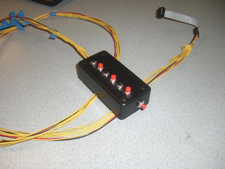
FIG 8: SWITCHING MECHANISM FOR CHORD AND INSTRUMENT CHANGES
This
circuit was relatively straightforward to design: Each button was a small toggling pushbutton
switch, default closed. Each pushbutton
was fed a 5V supply voltage, and was followed by a resistor connected to
ground. Between the switch and the
resistor was the voltage signal point.
Consequently, each switching signal was constant at VCC, but would be
sent to 0V when the button was depressed.
This method of button input was very similar to the default-high button
press delivered from the Atmel644 board that we were used to.
Digital to
Analog Conversion
The
sound output was delivered as an 8-bit value between 0 and 255, indicating the
amplitude of the sound wave at any given point.
This output is incompatible with analog speakers which require voltage
amplitude variations, so the digital to analog section of hardware was required
to convert an 8-bit digital
signal representing amplitude to an analog voltage differential signal.
Fortunately,
this was made very easy by the DAC0802 made by National Semiconductor. The DAC0802,
pictured below, was a Digital to Analog conversion chip, providing an analog
voltage based upon an 8-bit input signal.
This worked perfectly for our application, quickly giving us the format
necessary for speaker output.
Furthermore, it was fast-response, so it was capable of delivering information
at the high frequencies necessary to produce sound output. The DAC had a frequency cutoff of 8 kHz.
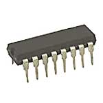
FIGURE 9: DAC0802 DIGITAL TO ANALOG
CONVERTER
Following
the DAC, we had a small amplification circuit, which served as a buffer,
followed by a small low-pass filter to adjust our signal and prepare it for
speaker output. The signal was then fed
into two small speakers via a 3.5 mm cable jack and delivered to powered
speakers.
Aside
from this hardware, there was a simple frame we built using spare plywood, lab
stands and C-clamps. A picture of our
complete setup is here:
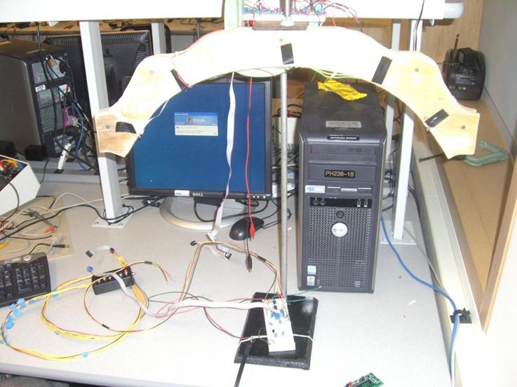
FIGURE 10:
COMPLETED STAND FOR LEDZEPPELIN HARP
RESULTS AND CONCLUSION
We were very
pleased with the ultimate outcome of our design. Our final project was capable of everything
we set out to accomplish. Namely, it
provided 5 notes of 6 different chords, providing 30 possible combinations of
notes to play. Furthermore, the
instrument is capable of changing its base waveform, allowing for adjustments
in tone as the user sees fit. One
problem we reached while testing and debugging the harp was the consequences of
ambient light, specifically the gradient between mid-day light from the sun to
evening lab conditions. The photodiode
sensitivities adjust accordingly, so no constant voltage comparator would serve
in each condition. Instead, we implemented variable resistances to either
increase or decrease the values of the voltages to fine-tune the instrument for
any light condition. This is akin to
physical instrument musicians tuning before playing.
If we were to redo
this experiment, we would hope to implement further chord possibilities than
the six we have implemented here. To
implement the full musical spectrum that an Autoharp does, we would need
several times as many chord combinations as we have programmed here. However, that is just a simple adjustment of
code and arithmetic, and as a prototype our LED based harp demonstrates the
capability to expand to become fully capable of playing any combination of
notes easily and effortlessly.
Applications
As for commercial
applications, the main application we have found would be as a musical
instrument for alternative performance to a synthesizer piano. The harp has a slightly different playing
philosophy, relying on sweeps of hands rather than key depressions, allowing
for a variation in playing style.
Furthermore, we inadvertently attracted the attention of the Sciencenter
in downtown Ithaca, who expressed interest in applying our concept to a
demonstration model for children learning about light and music. At our low cost, it would seem to be an
extremely attractive product for many such science museums to purchase, as the
low required maintenance on a strings and buttons-free musical instrument
demonstration would allow for a long lifetime.
Accuracy
We found that the
accuracy of the sensor arrays was highly tunable, and via the potentiometers,
the pluck sensing came to be as accurate as we wanted to make it, given the
restrictions of the 10kOhm trimpot. Our
harp sounded indistinguishable from actual tones found in music, but we
examined the accuracy of our frequency outputs to determine just exactly how
precise our timing was. Below is a rough
examination of our frequency results:
|
DESIRED FREQUENCY
|
MEASURED FREQUENCY
|
|
415.3
|
413-417
|
|
440
|
438-441
|
|
493.9
|
487-494
|
|
554.4
|
550-556
|
|
587.3
|
582-590
|
|
659.3
|
654-6
|
|
740
|
737-741
|
|
830.6
|
827-833
|
|
880
|
875-882
|
|
987.8
|
985-995
|
|
1108.7
|
1104-1114
|
|
1174.7
|
1170-1179
|
|
1318.5
|
1311-1321
|
TABLE 3: SAMPLED FREQUENCY TESTS AND MEASURED RANGES
Ethical
Considerations
During
the design and implementation of the LEDzeppelin Harp, we made sure to pay careful
consideration to the IEEE Code of Ethics.
Regarding personal safety, we wanted to make sure that playing the harp
would not cause adverse health effects or injury.
While the user
hardly comes in contact with anything while playing the harp, it doesn’t mean
injury is completely ruled out. As a
matter of fact, Infrared light has the potential to damage eyesight,
potentially leading to blindness.
To the best of our
knowledge, this device does not infringe any sort of standard; some research
was necessary to ensure the infrared-emitting LEDs were not dangerous to the
human eye, but the voltage and current we provide the LEDs would have to be
focused to a tiny spot to do any damage, just like other visible LEDs in their
range.
In terms of
intellectual property, we did not consciously plagiarize any code; our code,
while borrowing on concepts learned in class, was entirely written from scratch
and implements design choices made by ourselves alone, with suggestions from
family and friends.
APPENDIX 1 – COMMENTED CODE
// Ken
Colwell, Steve Fuertes
// ECE 476
Final Project
// April 2009
// Outputs
8-bit DDS through PORTB
// in response
to "strings" on PINC
// and
"chords" on PIND
#include
<inttypes.h>
#include
<avr/io.h>
#include
<avr/interrupt.h>
#include
<math.h> // for sine, exp
#define
countTenMS 78 // ticks per
10mSec
#define FULL
255 // bottom of
the hourglass; FULL == out of time
#define
ALLSTRINGS 5 // NUMBER OF
STRINGS ON PORTB
#define G_MOD
32.0 // sharpness
of Gaussian
// output
controls
#define
SIGNALPORT PORTB
#define
SIGNALDIR DDRB
// input
controls
#define
STRINGPIN PINC
#define
STRINGDIR DDRC
#define
CHORDPIN PIND
#define
CHORDDIR DDRD
// notes
const long
incTable[14] = {228313667L, // G#
241892640L, // A (440 Hz)
271524488L, // B
304784726L, // C#
322871699L, // D
362454131L, // E
406819440L, // F#
456627334L, // G#
483785280L, // A (880 Hz)
543048977L,
// B
609514477L,
// C#
645798373L,
// D
724853286L,
// E
0L}; // default, kills string
// The DDS
variables
volatile unsigned
long accumulator[ALLSTRINGS];
volatile unsigned
char highByte[ALLSTRINGS];
volatile unsigned
long increment[ALLSTRINGS];
volatile unsigned
char hourglass[ALLSTRINGS];
// tables for
DDS
unsigned char
sineTable[256] ;
unsigned char
squareTable[256] ;
unsigned char
sawTable[256] ;
unsigned char
triTable[256] ;
unsigned char
gaussTable[256] ;
unsigned char
rampTable[256] ; // envelope
table: sharp decay, long release
unsigned long
currentNote[5] ; // holds notes
in the currently-selected chord
unsigned char
currentInc[ALLSTRINGS] ; // each string
has one of these;
// it describes which increment is
attached to the string: (0,1,2,3)
// if the string is the oldest-played
it gets 4 and doesn't play
unsigned char
oldestInc, thisString;
volatile unsigned
int time, waveTime; // secondary
timers driven off of "count"
volatile char
count; // primary ISR
timer
volatile int
ii,jj; // index vars
used in ISR and main()
volatile char
chordNum, waveNum; // state variables: which chord, which
waveform
void initialize(void); // boot
processes
ISR
(TIMER0_OVF_vect) //EVERY 128us:
{
// run the accumulators through the
table
for(ii=0;
ii<ALLSTRINGS; ii++)
{
accumulator[ii] += increment[ii] ;
highByte[ii] = (char)(accumulator[ii]
>> 24) ;
}
// output additive 8-bit signal to the
DAC
switch (waveNum)
{
default:
case 0:
SIGNALPORT =
((sineTable[highByte[0]]*rampTable[hourglass[0]])>>8)
+ ((sineTable[highByte[1]]*rampTable[hourglass[1]])>>8)
+
((sineTable[highByte[2]]*rampTable[hourglass[2]])>>8)
+
((sineTable[highByte[3]]*rampTable[hourglass[3]])>>8);
break;
case 1:
SIGNALPORT =
((squareTable[highByte[0]]*rampTable[hourglass[0]])>>8)
+
((squareTable[highByte[1]]*rampTable[hourglass[1]])>>8)
+
((squareTable[highByte[2]]*rampTable[hourglass[2]])>>8)
+
((squareTable[highByte[3]]*rampTable[hourglass[3]])>>8);
break;
case 2:
SIGNALPORT =
((triTable[highByte[0]]*rampTable[hourglass[0]])>>8)
+ ((triTable[highByte[1]]*rampTable[hourglass[1]])>>8)
+
((triTable[highByte[2]]*rampTable[hourglass[2]])>>8)
+
((triTable[highByte[3]]*rampTable[hourglass[3]])>>8);
break;
case 3:
SIGNALPORT =
((sawTable[highByte[0]]*rampTable[hourglass[0]])>>8)
+
((sawTable[highByte[1]]*rampTable[hourglass[1]])>>8)
+
((sawTable[highByte[2]]*rampTable[hourglass[2]])>>8)
+
((sawTable[highByte[3]]*rampTable[hourglass[3]])>>8);
break;
case 4:
SIGNALPORT =
((gaussTable[highByte[0]]*rampTable[hourglass[0]])>>8)
+
((gaussTable[highByte[1]]*rampTable[hourglass[1]])>>8)
+
((gaussTable[highByte[2]]*rampTable[hourglass[2]])>>8)
+
((gaussTable[highByte[3]]*rampTable[hourglass[3]])>>8);
break;
}
// generate time base for MAIN
// 78 counts is about 10 mSec
count--;
if (0 == count )
{
count=countTenMS;
for (ii = 0;
ii<ALLSTRINGS; ii++)
if (hourglass[ii] < FULL)
hourglass[ii]++; //
"age" the strings
time++;
}
}
int main(void)
{
initialize();
while(1)
{
if (time==5) //...then 50ms
have elapsed
{
time=0; //reset timer
/**/ // POLL STRINGS
for (thisString=0;
thisString<ALLSTRINGS; thisString++)
{
if ( (~STRINGPIN) & (1<<thisString) ) //...then the
string is being plucked
{
if
(currentInc[thisString] < 4) //...then it's already attached to an
increment
{
increment[currentInc[thisString]]
= currentNote[thisString]; //reset freq
hourglass[currentInc[thisString]]
= 0; //play the note
}
else //...it isn't,
so take the oldest one and give it to thisString
{
//find the
oldest hourglass
oldestInc=0;
for (jj=1; jj < 4; jj++)
{
if
(hourglass[jj] > hourglass[oldestInc])
oldestInc
= jj;
}
//set that
string's inc to 4
for (jj=0; jj <
ALLSTRINGS; jj++)
{
if
(currentInc[jj] == oldestInc)
currentInc[jj]
= 4;
}
//set the new
string's inc to oldestInc and play the note
currentInc[thisString]
= oldestInc;
increment[oldestInc]
= currentNote[thisString];
hourglass[oldestInc]
= 0;
}
}
}
/**/
// POLL CHORD BUTTONS (logic LO is
button PRESSED)
for (ii=5; ii>=0; ii--)
if (((~CHORDPIN) &
(1<<ii))
> 0) chordNum = ii;
/**/ // CHANGE CHORD
switch (chordNum)
{
case 0: // A MAJOR
currentNote[0] = incTable[1];
currentNote[1] = incTable[3];
currentNote[2] = incTable[5];
currentNote[3] = incTable[8];
currentNote[4] = incTable[10];
break;
case 1: // B MINOR
currentNote[0] = incTable[2];
currentNote[1] = incTable[4];
currentNote[2] = incTable[6];
currentNote[3] = incTable[9];
currentNote[4] = incTable[11];
break;
case 2: // C# MINOR
currentNote[0] = incTable[0];
currentNote[1] = incTable[3];
currentNote[2] = incTable[5];
currentNote[3] = incTable[7];
currentNote[4] = incTable[10];
break;
case 3: // D MAJOR
currentNote[0] = incTable[1];
currentNote[1] = incTable[4];
currentNote[2] = incTable[6];
currentNote[3] = incTable[8];
currentNote[4] = incTable[11];
break;
case 4: // E MAJOR
currentNote[0] = incTable[2];
currentNote[1] = incTable[5];
currentNote[2] = incTable[7];
currentNote[3] = incTable[9];
currentNote[4] = incTable[12];
break;
case 5: // F# MINOR
currentNote[0] = incTable[1];
currentNote[1] = incTable[3];
currentNote[2] = incTable[6];
currentNote[3] = incTable[8];
currentNote[4] = incTable[10];
break;
default:
break;
}
/**/
//SEVENTH BUTTON TOGGLES WAVEFORM;
"debounced" via timer for holdable swap
if ((~CHORDPIN) & 0x40)
{
waveTime++;
if
(waveTime >= 4)
{
waveTime
= 0;
if (waveNum < 4) waveNum++;
else waveNum = 0;
}
}
} // end 50ms timer
} // end while(1)
} //end main
void initialize()
{
// set up output and input ports
SIGNALDIR = 0xff ;
STRINGDIR = 0x00 ;
CHORDDIR = 0x00 ;
// init the tables
// ALL tables range between 0-63 so we
can add for 4x polyphony on an 8-bit DAC
for (ii=0; ii<256; ii++)
{
sineTable[ii] = (char)(32.0 + (31.0 * sin(6.283*((float)ii)/256.0))) ;
//note that the Gaussian table below
can be tuned "sharper" by decreasing defined G_MOD
gaussTable[ii] = (char)(63.0*exp(-1.0*(((((float)ii)-128.0)/G_MOD)*((((float)ii)-128.0)/G_MOD))));
sawTable[ii] = ii/4;
if (ii < 128) {
squareTable[ii] = 63;
triTable[ii] = ii/2;
}
else {
squareTable[ii] = 0;
triTable[ii] = 128 - ii/2;
}
}
for (ii=0; ii<10; ii++) // Construct
amplitude envelope
{
rampTable[ii] = (255-10*ii);
} for (ii=10; ii<174; ii++) {
rampTable[ii] = (174-ii);
} for (ii=174; ii<256; ii++) {
rampTable[ii] = 0;
}
// initialize strings
for (ii=0;
ii<ALLSTRINGS; ii++)
{
accumulator[ii] = 0L;
hourglass[ii] = FULL;
currentInc[ii] = ii;
}
// initialize timers
count = countTenMS;
time=0;
waveTime=0;
// initialize to chord 0, A Major
chordNum = 0;
for (ii=0; ii <
ALLSTRINGS; ii++)
increment[ii] = currentNote[ii];
// init waveform to sine
waveNum = 0;
// timer 0 runs at 1/8 full rate
(check this but I'm pretty sure. page
100 of datasheet)
// one clock tick every
TCCR0B = 2 ;
//turn on timer 0 overflow ISR
TIMSK0 = (1<<TOIE0) ;
// turn on all ISRs
sei();
}
/***********************************NOTES******************************
for a 32-bit
DDS accumulator, running at 16e6/2048 Hz:
increment =
549756*frequency
SETUP:
DAC output is on port B
"string" inputs are on port C
"chord" and "wave"
inputs are on port D
*/
APPENDIX 2 – SCHEMATICS

FIG 11: LED CIRCUIT DIAGRAM (EX)
FIG 12: TWO-STAGE OP-AMP DRIVEN AMPLIFICATION AND COMPARE CIRCUIT (EX)

FIG 13: SWITCHING CIRCUIT DIAGRAM (EX)
APPENDIX 3 – COST BREAKDOWN
|
Part
|
Cost/part
|
Number Required
|
Total Cost
|
|
Mega644 Microcontroller
|
8
|
1
|
8
|
|
12V Power Supply
|
5
|
1
|
5
|
|
STK500 Development Board
|
15
|
1
|
15
|
|
Whiteboard
|
6
|
2
|
12
|
|
Pushbuttons
|
1.04
|
7
|
7.28
|
|
Plastic Remote Case
|
2.69
|
1
|
2.69
|
|
Infrared LED
|
1.99
|
2
|
3.98
|
|
Infrared Photodiode
|
0.6
|
10
|
6
|
|
Digital-to-Analog Converter
|
1.59
|
1
|
1.59
|
|
Scrap Wood
|
0
|
1
|
0
|
|
Scrounged Lab Stand
|
0
|
1
|
0
|
|
Scrounged Double Op-Amps
|
0
|
6
|
0
|
|
Scrounged Potentiometers
|
0
|
5
|
0
|
|
Scrounged Sound System
|
0
|
1
|
0
|
|
Scrounged 3.5mm Audio Jack
|
0
|
1
|
0
|
|
Scrounged Wire (in miles)
|
0
|
17
|
0
|
|
|
|
|
|
Total:
|
|
|
61.54
|
TABLE 4: COST
BREAKDOWN
APPENDIX 4 – CONTRIBUTIONS
This table outlines the
contributions from both team members:
|
Ken Colwell
|
Steve Fuertes
|
|
Built Harp Frame
|
Built Harp Frame
|
|
Website Content
|
Website Content
|
|
Sound Synthesis Code
|
Hardware Design
|
|
Chord Programming
|
Hardware Implementation and Assembly
|
|
Sound Filtering and
Shaping
|
Construction and Debug of
Sensor Arrays
|
|
Wave and Instrument
Adjustments
|
Debug of amplification battery
|
|
DAC and Audio Amplifier
Design
|
DAC and Audio Amplifier
Design
|
|
Frequency Testing
|
Harnessing work
|
|
Remote Control
Construction
|
Schematic Drawing
|
TABLE 5: RELATIVE CONTRIBUTIONS
APPENDIX 5 – REFERENCES
DAC0802 Reference Page: http://www.jameco.com/webapp/wcs/stores/servlet/ProductDisplay?langId=-1&storeId=10001&catalogId=10001&productId=14904&
High-output LED Reference Page: Model: 276-143  http://www.radioshack.com/product/inStoreAvail.jsp?productId=2062565
Infrared-sensitive
Photodiodes http://www.jameco.com/webapp/wcs/stores/servlet/ProductDisplay?langId=-1&storeId=10001&catalogId=10001&productId=1950649&
LED Wiring Guidehttp://www.kpsec.freeuk.com/components/led.htm
Buffered DAC circuit diagram http://sbhep-nt.physics.sunysb.edu/~hobbs/Phy335/Unit7.pdf
Frequency of musical notes (A440) http://www.phy.mtu.edu/~suits/notefreqs.html