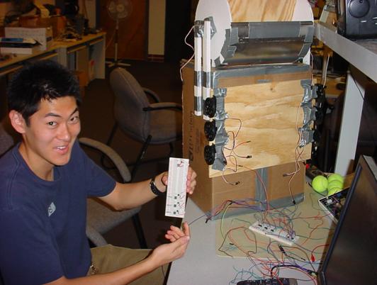
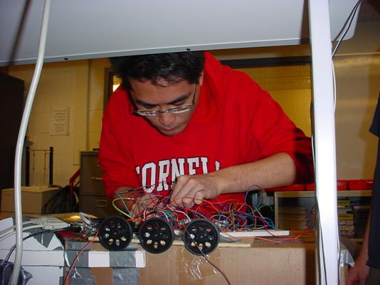
The Autonomous
Tennis Ball Picker
Charles Cheung (cc484), Peter Kung (pfk5)
Contents
Reference and Acknowledgements
In
the tennis and sports equipment market, there are very few advanced electronic devices
assisting in the feeding and picking of tennis balls or any other kind of
balls. Tennis players do not prefer picking up over five hundred balls after a
long day’s worth of drilling, or a baseball player would not enjoy picking up
over five hundred baseballs on the ground from batting practice. As a result,
our solution is an autonomous ball-picker device that is easy-to-use and
cost-effective. Our design can be used for a variety of sports besides tennis,
involving balls of similar size and weight.
Rationale and
Overview
There are
many ball-picking devices in the market today designed by Playmate, Gamma,
among others that are human-powered and human-controlled. However, there are almost
no existing sports products that are autonomous and do not require the labor of
a person. In a generation where the number of athletes is growing, where most
of them do not play professional but still compete at a high level, there is a
bigger demand for machines that make athletes’ lives simpler and less
time-consuming. As a varsity tennis athlete, I feel that a device to pick up a
large amount of tennis balls after practice would save about thirty minutes a
day for five days a week.
Our
project aims to devise an easy-to-use, low-cost autonomous ball-picking device
that helps pick up tennis balls, or perhaps any other balls of similar weight
and shape, over an enclosed tennis court area. The general idea is that this
device will sweep through a tennis court in a smart fashion within a reasonable
amount of time. A complex ball-search algorithm will be implemented to
eventually pick up all tennis balls within an enclosed area with fairly high
walls. The picker implements a rotary blade technology that pushes a tennis
ball up half-cylinder structure and over to the basket where it is stored. This
technology is similar to the Playmate’s Mower. The machine also contains
touch sensors for intelligent maneuvering when approached by walls or backdrops
as well for “mowing” the balls from the ground. This machine is roughly one
foot long, three feet wide and one and a half feet tall. Our final
construction is by no means a final product, since it is still a prototype
model that can be used for similar devices with this exact purpose.
ADC Conversion
Basics
The touch
sensor read feedback system utilizes an ADC conversion to transfer analog
voltage data from sensors being used to a digital signal to be processed in our
C program. The ADC converter takes in a range of voltage values converts the
value into a scaled fraction of an 8-bit data register, with a size of 28
= 256 values. The following equation shows the result of ADC conversion:
![]()
Converting the output voltage to a
whole number value between 0 and 255 can become very helpful in determining
whether a ball has passed or whether a wall is detected.
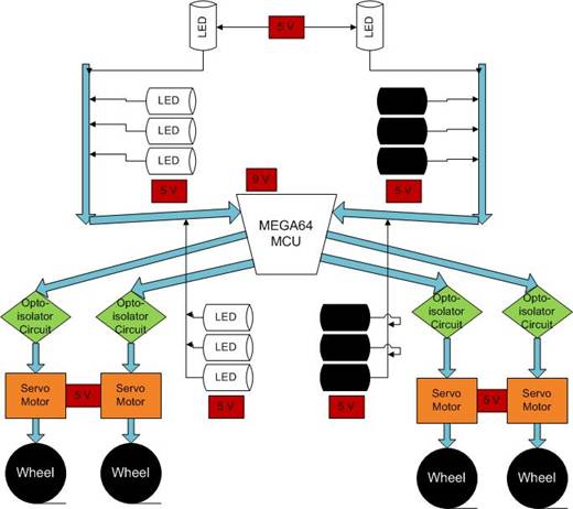
Logical Structure
and Diagram
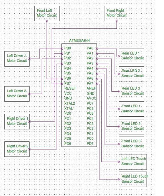
Our ball-picker device consists of two
main systems that all communicate with the MCU directly. The front touch
sensors at the top of Figure 1, the front and back LED ball-pass sensors all
output data to the MCU. All of the sensors are tied to a common ground and VCC
to save socket space. The other system is the motor driver circuitry. There are
four servo motors in the diagram, two on each side. They are each tied to
separate VCC and ground sources to create maximum power and torque. A general
visual conception of the main systems of our device is shown below:
Figure
1: Device Logic Structure Diagram
Hardware Tradeoffs
The
initial design of the motor driving system involved the use of stepper motors. Due
to its large amount of port connections and the absence of wheels that are
compatible, we switched the design to using servo motors because it was the
most cost-effective method for us, they required a reasonable number of port
connections (three for each motor), and they included wheels that came with
them. The downside is that the servo motors are difficult to calibrate and can
often times be unreliable for extensive continuous motion.
For the
touch sensors, we contemplated using accelerometers, or proximity sensors.
However, given the amount of resources we have already, we decided to use the
LED emitters and NPN phototransistors to detect objects. We tested the range of
the objects such that the NPN phototransistors vary in output voltage, and we found
that the object was far enough so that the device would have enough time to
back up before it collides with the object.
The amount
of power supply and torque behind the servo motors were analyzed. We found that
the there was not enough torque to drive the front blades if the VCC source was
tied commonly with the driving motors. Also, the driving motors would not be
able to have enough power to move the device if they were commonly tied to VCC
and ground. The only way to solve this issue was to use separate voltage
supplies for each system: Two VCC sources on each side of the device, and one
VCC source going into the rotary blades. This causes more battery packs than we
would have liked, but the battery life should be long enough so that they do
not have to be replaced as frequently.
Software Tradeoffs
When
outputting square wave pulse signals out of ports, one typically uses PWM mode
and inputs the voltage line in which the signal is high or low. However, we
decided to hard code the pulse signal output and avoided changing the registers
by setting the signal to high at a certain range of time and to low as well.
When studied through an oscilloscope, we observed that the output signal
exactly matches a square wave pulse. Therefore, I am convinced that our
hard-coded pulse signal functions correctly.
Relevant Patents
and Other Designs
There were a few patents designed
for tennis balls to be picked without any human labor or work. One patent
involved a long descending gutter placed against the back wall of
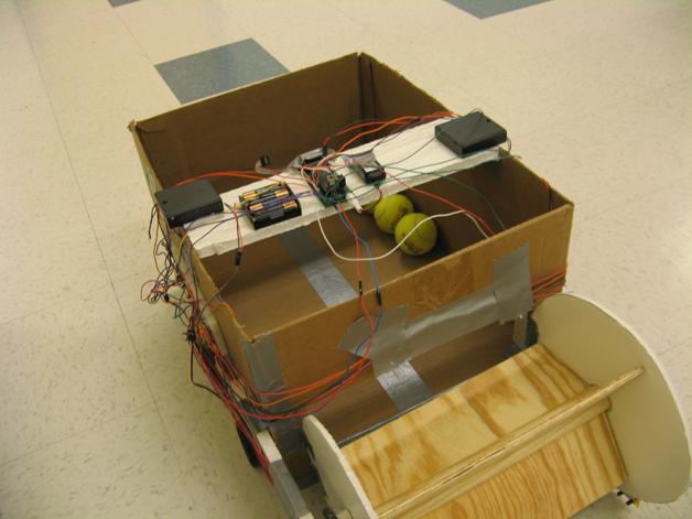
Mechanical Design
Due to
limited budget constraints, we used the most basic yet strong materials to
build the backbone of the autonomous ball-picker. The ball storage basket
comprises of cardboard withheld by duct tape. A wooden board is attached below
the basket to act as ground support to withstand heavy weight, and also serves
as a chassis for attaching servo motors on each side of the basket. A
rectangular hole is cut at the front of the basket for balls to fly in when
they are swept up.
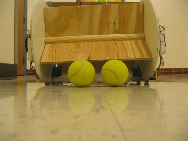
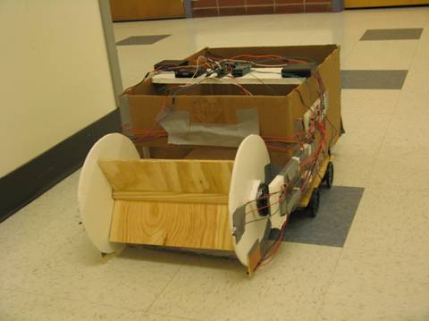
The front
side ball grabber comprises of three wooden blades positioned equidistantly
around a wooden cylinder. This wooden cylinder is turned by attaching a servo
motor and a wheel connector on each side. The wheel connector fixes the servo
motor with the cylinder so that all the torque of the motors is used for
turning the cylinder. This wooden blade system is supported by two circular
foam boards on each side. A tin sheet is used as a ramp just under the rotating
blades, and they are positioned a little above the ground, but low enough for
balls to be pushed in by the blades.
The weight
of the device is supported by plastic wheels, two on each side. These wheels
are strongly attached to the wooden board to prevent any detachments and
driving failures.
Hardware Setup
Servo Motor Circuitry
Our wheels
and front side rotating blades are all driven by Parallax Continuous Rotation
servo motors. Each motor has three inputs: VCC, ground, and a periodic square
wave signal. The pulse width of the square wave determines the speed and
direction of the servo motors. In our case, we only want to change the
direction to allow the device to move forward, backward, and turn left and
right. If the pulse width is under a certain time frame, the motor will drive
in a clockwise direction. If the pulse width exceeds that time frame, the motor
will drive in a counterclockwise direction. The middle time frame can be
adjusted through a built-in potentiometer inside the motor. The voltage of the
potentiometer can be manually changed with the use of a screwdriver. In our
project, we determined the middle dividing point to be 1.5 milliseconds. A
Parallax servo motor datasheet can be accessed here for further reference.
The servo
motors are opto-isolated to provide protection for the board from inductive
spikes released by the motors when they are turned off.
On the
other end, the input square wave signal is fed across a 1KOhm resistor and an
NPN BJT transistor. The gate voltage driving into the BJT transistor allows
current to flow across the source and drain, and thus causes the signal to be
driven across the opto-isolator and into the servo motors.
Two
general types of servo motor circuits were used. One circuit involved a common
ground and source between the motor end and the input signal end. This was only
used for the front rotation blades in efforts to synchronize the two servo
motors on each end for smooth turning. The other circuit involved separate
ground and VCC sources for the motor end and the signal end. This is strongly
preferred because it inhibits any chance of shortages or voltage conflicts.
Figure
2: Servo Motor Circuit Diagram
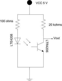
LED Sensor Circuitry
The LED
sensors are used both as touch sensors and pass-through sensors in our feedback
design. There are two pairs of LED emitters and NPN Phototransistors on the front of the rotary blades, and
they act as touch sensors for incoming walls or obstacles. Three pairs of LED
emitters and detectors are used just below and in front of the rotary blades to
sense if a ball has passed through and is ready to be picked up. The reason for
using these sensors at the bottom is to prevent the rotary blades from jamming
if they spin continuously. Three more pairs of LED emitters and detectors are
placed just behind the front hole of the basket. Their main purpose is to
detect that a ball has successfully been picked up and dumped into the basket.
If a ball was jammed midway while being pushed up by the rotary blades, these
sensors can help us conclude that the ball is still in the rotary wheel, and
therefore the direction of the blades must be reversed to fix the jam.
For the
NPN Phototransistors, the detection of LED light corresponds to its voltage
output. The more the phototransistors detect LED, the lower the voltage. In the
case of the front side touch sensors, we determined a specific threshold
voltage of about 3.5 – 3.7 V from a VCC of 5.0 V to allow the sensor to be activated.
Once the phototransistor’s output voltage reaches below that threshold, it can
be concluded that a wall is nearby and the appropriate action can be taken. In
the case of the bottom and back side ball-pass sensors, we determined a
specific threshold voltage of about 1.8 – 2.0 V from a VCC of 5.0 V. By
default, the LED emitters are positioned in line with the phototransistors
which cause a very low voltage output of 0.18 V. When a ball is passed through,
the phototransistors increase in voltage output. Any voltage above the
threshold would indicate that a ball has passed through.
Figure
3: LED emitter and NPN Phototransistor Circuit Diagram
State
Machine
There are
two state machines in the project: Front wheel and Rear wheel. The front wheels
pick up the tennis balls, and the rear wheels move the whole tennis ball
picker.
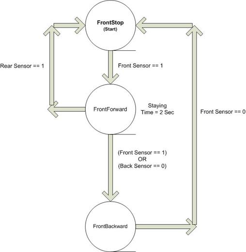
Front
Wheel
There are three
states for the Front wheel state machine, and their functions are as follows:
FrontStop:
It stops and waits to pick up balls.
FrontForward: It moves forward to pick up the
tennis ball.
FrontBackward: It moves backward in case the ball
gets stuck.
The state
machine starts at the FrontStop state. If the front sensor detects a
ball (Front Sensor == 1), it will change to the FrontForward state such
that the motors can move forward to pick up the ball. The picker will stay in
the FrontForward state for two seconds. After that period, if the rear
sensor detects a ball crossing through, it means the ball is dropped into the
pick up box (BallCross == 1), and the ball counting is increased by one (count
= count++). It will change to the FrontStop state to stop the wheels. If
either the front sensor is still detecting the ball or the rear sensor does not
detect a ball crossing through, it means the ball is stuck in the blades. The
Front Wheel state then changes to the FrontBackward state such that the
motors can move backward to push out the balls. At the same time, the Rear
Wheel state changes to the RearStop state such that the picker can stop and
allow the front blades to push the ball outwards. The picker can then have a
second trial to pick up that ball. The picker stays in the FrontBackward
state until the front sensor does not detect the ball. It means the ball is not
stuck anymore, and it will change to the FrontStop state and start over
again.
Figure
4: The FrontWheel state machine
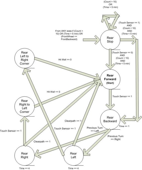
Rear
Wheel
There are
seven states for the rear wheel state machine, and their functions are as
follows:
RearStop:
The picker stops when it picks up more than 10 balls or time is greater than 10
minutes.
RearForward: The picker moves forward.
RearBackward: The picker moves backward.
RearLeft: The picker moves to the left.
RearRight: The picker moves to the right.
RearLefttoRightCorner: The picker moves to the left
originally, but it senses a wall, so it moves to the right.
RearRighttoLeftCorner: The picker moves to the right
originally, but it senses a wall, so it moves to the left.
The state
machines starts at the RearForward state. If the touch sensor detects a wall
in front (Touch Sensor == 1), it will change to the RearBackward state
such that the motors can move backward for one second. It the previous turn is
to the right, it changes to the RearLeft state this time. If the
previous turn is to the left, it changes to the RearRight state this
time. It takes approximately two seconds to make a U-turn, so the picker will
stay in the RearLeft or RearRight state for two seconds to
complete the U-turning if the touch sensor does not detect another wall during
that 2-second period (Touch Sensor == 0). After that 2-second period, the
picker changes to the RearForward state and continues to move forward.
If the touch sensor senses a wall during that period (Touch Sensor == 1), it
means the picker is at a corner. There is more than one wall surrounding the
picker. Therefore, the picker either changes from the RearLeft to RearLefttoRightCorner
state or from the RearRight to RearRighttoLeftCorner state.
In the RearLefttoRightCorner
state, the picker first turns backward for one second. After that, it turns to
the right for one second. If the touch sensor does not sense a wall during the
one-second period, it means the picker moves out of the corner and is moving
parallel to the wall. The picker then moves to the right for 90 degrees, which
takes about one second. Eventually, it changes to the RearForward state
to continue sweeping the floor.
In the RearRightLeftCorner
state, the picker first turns backward for one second. After that, it turns to
the left for one second. If the touch sensor does not sense a wall during the
one-second period, it means the picker moves out of the corner and is moving
parallel to the wall. The picker then moves to the left for 90 degrees, which
takes about one second. Eventually, it changes to the RearForward state
to continue sweeping the floor.
In any
state, if the number of balls picked up is greater than ten, or if the time
exceeds five minutes, it changes to the RearStop state.
Figure
5: The RearWheel state machine
ADC
Software Design
The output
of the sensors is connected to the Analog-to-Digital converter input (PORT A)
of the Mega644. The 5-V analog output is converted into a number between 0 and
255. If there is nothing in between the emitter and transmitter, the analog
output will be close to 0 V, and the digital output will be close to 0. If
there is something in between the emitter and transmitter, the analog output
will be close to 5 V, and the digital output will be close to 255.
For the
front and back sensors, when there is no ball crossing through, the digital
output should be close to 0. If there is a ball in between, the digital output
will be close to 255. Therefore, a threshold of 100 (about 1.96 V in analog) is
set to determine if a ball crosses through the sensors. For the touch sensors,
when there is no wall in front, the emitted light from the LED cannot be
detected by the phototransistor. Therefore, the output is close to 255. When
there is a wall in front of the sensors, the emitted light from the LED is
reflected by the wall to the phototransistor. Therefore, the output is close to
0. A threshold of 150 (about 2.94 V in analog) is set to determine if a wall is
in front of the picker.
An example
of our software design of the ADC implementation is shown below:
// Rear Sensor: If at least 2 of the 3 sensors are
activated
//
it means a ball has passed through
if
(Ain1>limit) CountRear++;
if
(Ain2>limit) CountRear++;
if
(Ain3>limit) CountRear++;
if
(CountRear>=2) { IsbackSensor = 1; }
else
{ IsbackSensor = 0; }
//
Front Sensor: If at least 2 of the 3 sensors are activated
//
it means a ball has passed through
if
(Ain4>limit) CountFront++;
if
(Ain5>limit) CountFront++;
if
(Ain6>limit) CountFront++;
if
(CountFront>=2) { IsFrontSensor = 1; }
else
{ IsFrontSensor = 0; }
if ((Ain0<touch_limit) || (Ain7<touch_limit))
begin
IsTouchSensor
= 1;
end
else
IsTouchSensor = 0;
If at least
two out of the three receivers of the rear sensor record an output greater than
100, there is a ball crossing through the rear sensors, and the variable Isbacksensor changes to 1. Similarly, if two out of the three front
sensor receivers record an output greater than 100, there is a ball crossing
through the front sensors, and the variable IsFrontSensor
changes to 1. If any of the two touch sensor receivers record an output
less than 150, there is a wall in front, and the variable IsTouchSensor changes
to 1.
Pulse-Width
Modulation for Motor Control
The servo
motors can be controlled by generating a 50-Hz square-wave pulse (each period
is 20ms) to the input of motors. There is a potentiometer inside the motors, and
the motion of the motors is controlled by the potentiometer and the input pulse
width. At the beginning, a 1.5 ms pulse-width square-wave is input to the motor
such that the motors are in the stop state. If the motors are not stopping, a
screw driver is needed to insert into the hole of the servo motors until the
motors stop such that the potentiometer can be changed to the right potential.
It is important to make sure that every motor is changed to the same potential.
Otherwise, the motors may move in random direction or don’t move at the same
speed. A 1.5ms pulse width example is shown in Figure C. A 0.5 ms-pulse is
input to the motors in order to drive them in the clockwise direction.
Similarly, 2 ms-pulse is input to the motors to drive them in the counter-clockwise
direction.
Figure 6: 2-ms pulse-width input to
the motor for moving counter-clockwise
Figure 7: 0.5-ms pulse-width input
to the motor for moving clockwise
Figure 8: 1.5-ms pulse-width input
to the motor for stopping

The code below is an
example of how the pulse signal is generated. We implement the time counter in
Timer0 Overflow ISR. It takes 1/62 ms per tick. In order to generate a
20ms-period square wave, a pulse counter of 1240 is used to count for each
period. In the following moveMotor
function, if the pulse counter is less than 31 (which corresponds to 0.5 ms),
the signal output from the MCU is set to one. Otherwise, the output is set to zero.
In this way, we can generate a square-wave output of 20ms-period and
0.5ms-pulse width. The function is implemented every 1/62 ms such that the
picker can update its motion as quick as possible.
//moveMotors
function: Set direction of motors
void moveMotors(int
left1, int right1, int left2, int right2)
begin
// LEFT SIDE
if ((pulse_count<left2)) //Port B0
signal
= signal | 0x01;
else
signal
= signal & 0xfe;
if ((pulse_count<left2)) //Port B2
signal
= signal | 0x04;
else
signal
= signal & 0xfb;
if ((pulse_count<left2)) //Port B4
signal = signal |
0x10;
else
signal = signal &
0xef;
end
We have
surpassed many successful fixes and encountered many bugs in the mechanical,
hardware, and software side of the design. Overall, we were satisfied with the
significant amount of progress we made and the robustness and complexity of the
device given our limited budget constraint.
When
fitting the pieces of the mechanical device together, we first used duct tape
and carpenter’s glue to hold everything together. The servo motors were still
easily detached when placed under the wood board.
At first, the
servo motors we used seemed reliable and dependable. After calibrating and
testing each motor so that they function correctly as a whole, their movement
precision declines through time. Also, we found that the motors also respond
differently in various surrounding environments. For example, when the motors
are tested while hanging loosely, they all function correctly. However, when a
motor is glued onto the device, its direction and speed of motion change almost
randomly. Furthermore, it becomes immensely more difficult to recalibrate the
motors while they are glued because their dividing time period (about 0.5 ms)
is not as apparent. After further testing, we discovered that the servo motors’
internal potentiometer changes through time, so they need to be recalibrated
every time before use. As a result, we did our best in recalibrating the motors
before testing and making sure the wheels are turning in the right direction.
On the
software end, our state machine was fully functional and needed no human maneuverability
to move the device. Our program contained about a 10-20 millisecond delay when
changing states, which caused timing problems with synchronizing the read
feedback with the corresponding output states. We tested various combinations
of code such as placing the read sensors before the entire state machine, or
placing the touch sensors right before the rear wheel state machine and the
ball-pass sensors right before the front wheel state machine. The second method
had a smaller response time by about 0.5 seconds between reading and writing,
so that methodology was kept for our final algorithm. Our final program
resulted in a read/write response time within 500 milliseconds.
When we
moved the read sensor code to right before the RearWheel and FrontWheel
state machine functions, we noticed that the reaction times between the sensor
is read and the motor movements have improved from about two seconds to less
than one second. This improvement prevented the device from actually colliding
with walls and other wall objects.
There were
a few rare or unusual cases that we did not consider while implementing our
ball-search algorithm. One case is when the front blades are positioned such
that no ball can be within range of the bottom LED sensors. This means that a
ball would never be moved unless the blades move. One idea we had was to
activate the motion of the front rotary blades continuously at a constant time
interval. With the lack of the amount of time allotted, we were not able to
devise the most efficient code to deal with this specific case and decided to
have the user reset the device if such an event occurs.
One
problem we could not fix was improper programming onto the prototype board.
Sometimes after programming, the device moves in random order, and the servo
motors are moving in opposite directions. We tried recalibrating the wheels and
double checked all the pin connections. We also checked the AVR studio
programming setting with the fuses and other parameters. We also checked to see
if no chip, socket, or pin was dead when programming. None of our tests seemed
to fix this problem.
The
opto-isolated square wave input that is driven to the servo motors contained a
little bit of noise, but they were small enough to be ignored.
Overall,
the device is very usable and undergoes intelligent movement across a confined
area expectedly, and effectively picks up tennis balls within a confined area.
The user only needs to push the power switch on or off. Also, if the device is
permanently jammed or collided with a wall or some other object, the device
needs to be picked up and deactivated immediately by the user.
Expectation of the product
The final product is below our
expectation only because of the unreliability of the motors. The potential
inside the potentiometer changes very often which makes the motors unreliable
for long term usage. Repeated calibrating of the potential is needed to ensure
the effectiveness of the motors. Therefore, step or DC motors should be used
instead in which they don't have this problem. On the other hand, the LED and
phototransistors work very well. They are very accurate and have a sharp cutoff
in determining if a ball crosses through or not. In fact, the sensors can
detect as far as 30 cm. The state machine code works well, and it can instruct
the picker to pick up balls when the sensors detect something is in between.
Overall, if the servo motors are replaced by step or DC motors, the final
product will perform much better and can make the turning more smoothly. Also,
the speed of our robot can be increased to accelerate the ball pick-up process
with DC motors that have greater torque. The tennis court is fairly large, so
speed is an important factor in maximizing the efficiency of picking up most,
if not all, of the balls on the court.
We use one 9-V battery and 3 battery
packs (12 AA batteries) in the product. Since six motors are used, and they
drive much power from the batteries, they can only be used for 30 minutes.
After that, they need to be replaced. Therefore, it is expensive to use typical
batteries as power source. If the product is put into the market, Lithium
rechargeable batteries should be used. It can make the picker less bulky, and
the batteries can last much longer.
In the future, we may use the camera
to improve the efficiency of picking up balls. The inclusion of camera can
reduce the amount of time of finding a tennis ball in the court as we don't need
to sweep through the whole court anymore. Instead, we just use the camera to
search if there is any yellow object around the picker.
Intellectual Property Considerations
In the software end, the final program code was
created from scratch. No other design was used there. In the hardware end, the
servo motor circuitry was modeled after a previous robot design project of a
video-guided, ball-following robot in Bruce Land’s ECE 5760 course. The LED
emitter-detector circuitry was modeled after one of Bruce Land’s Neurobiology
courses (BioNB 442) of creating a finger plethysmograph. The mechanical design
was also created from scratch.
A patent for our autonomous ball-picker is possible,
although it is far from being a final product for sports equipment market.
However, with the budget costs and the popular demand of such machines on the
sports filed, the ideas and technology of this device can be applicable for
consumer use and therefore a patent for this type of machine will certainly be
considered.
Ethics
We follow
the IEEE codes of ethics closely in this project, and we consider safety as our
top priority in developing the product. Since there may be other tennis
players in the tennis court, we need to ensure that the tennis ball picker will
not hurt other players’ legs while it picks up the balls. This is done by
installing a touch sensor in front of the ball picker. If the sensor detects
anything, the picker will change the direction so that it won’t hit the player.
Moreover, we ensure that the motors rotate at a moderate speed and run smoothly
such that it will have enough time to change direction before hitting any
player or wall. It is assumed that the picker is used after the players have
finish playing. There will not be any moving object in the tennis court. It
ensures that any additional tennis ball will not hit the picker while the
players are playing tennis.
When we
design the picker, we notice the sharp edges of the wood blades as well as the
tin sheets. We are extremely careful in cutting the tin sheets and blades such
that we won't hurt ourselves and other classmates. We also put in signs to warn
other classmates away from the sharp tin sheets.
We take
Playmate’s Mower as a reference in designing our product, and we avoid
conflict of interest as much as possible. All components used in our final
project including the codes are compliant to current rules and regulations.
There are no legal considerations.
We would like to thank Professor
Bruce Land for his support in this project. He guided us in testing the LED and
phototransistors. He also helped us solving the STK board problem when we
tested the Analog-to-Digital converter. We would also like to thank our TAs,
Shane Pryor for his advice in modifying the ball picker design, Matt Meister
for his help in testing the servo motors, and Cathy Chen for her generous
assistance in designing and debugging the servo motor circuit.
Datasheets
NPN Phototransistors (LTR4206)
Web Sites
Task Breakdown
Peter Kung
· Mechanical construction –
Gluing pieces together, Cutting and resizing wooden pieces and tin pieces
· Circuit board construction –
Soldering, cutting wires, etc.
·
Hardware
combination – connecting electrical parts together, testing electrical
characteristics of each component
· Software debugging – i.e.
checking timing concerns and analyzing code efficiency and structure
· Wrote Introduction, high level
design, hardware design, schematics, and testing and results component of the
final lab report
Charles Cheung
· Hardware combination –
connecting electrical parts together, testing electrical characteristics of
each component
· Software design and
implementation – State machine design, timing design
·
Hardware debugging –
i.e. using oscilloscope to observe waveform output
·
Web page design
· Wrote software design and
conclusions of final lab report
Schematics
Hardware
design:
Figure 2: Servo motor
circuit diagram
Figure 3: LED sensor
circuit diagram
Figure
9: Prototype board schematic
Figure
9: ATMEGA644 Prototype Board Schematic
Budget
The budget
of this project is limited to $75 per team. In our project, we spend $58.8 on
the mechanical and electrical parts, which is within the budget.
|
Type |
Parts |
Quantity |
Unit
Cost |
Total
Cost |
Source |
|
Mechanical |
Cardboard
basket |
1 |
- |
- |
Scrap |
|
Mechanical |
Wooden
board/blades |
1 |
$4.00
|
$4.00
|
Bought
at Lowe's |
|
Mechanical |
Foam
board |
1 |
- |
- |
In
Lab |
|
Mechanical |
Duct
tape |
1 |
- |
- |
In
Lab |
|
Mechanical |
Tin ramp |
1 |
$5.00
|
$5.00
|
Bought
at Lowe's |
|
Electrical |
2.5V
AA Batteries |
3 |
$2.00
|
$6.00
|
Bought
at Rite Aid |
|
Electrical |
9 V |
1 |
$2.00
|
$2.00
|
Bought
at Rite Aid |
|
Electrical |
|
3 |
- |
- |
In
Lab |
|
Electrical |
Servo
motors |
6 |
- |
- |
In
Lab |
|
Electrical |
Wheels |
6 |
- |
- |
In
Lab |
|
Electrical |
LED
emitters |
8 |
- |
- |
In
Lab |
|
Electrical |
NPN
Phototransistors |
8 |
$0.125
|
$1.00
|
Bought
at Digikey |
|
Electrical |
Prototype
board |
1 |
$4.00
|
$4.00
|
In
Lab |
|
Electrical |
ATMega644 |
1 |
$8.00
|
$8.00
|
In
Lab |
|
Electrical |
White
boards |
4 |
$6.00
|
$24.00
|
In
Lab |
|
Electrical |
Small
Solder boards |
2 |
$1.00
|
$2.00
|
In
Lab |
|
Electrical |
DIP
Socket |
2 |
$0.50
|
$1.00
|
In
Lab |
|
Electrical |
SIP/Header
Socket |
36 |
$0.05
|
$1.80
|
In
Lab |
|
|
Total |
|
|
$58.80 |
|
Source
Code