Ultrasonic Haptic Vision System
Introduction
The ultrasonic haptic vision system enables a person to navigate hallways and around large objects without sight, through the use of an ultrasonic rangefinder that haptically interfaces with the user via tiny vibrating motors mounted on the users head. The idea behind this project was to construct a sixth sensory system that interacts with the body in an intuitive and user friendly fashion and enables the user to navigate without vision. We also implemented RF transmission in order to provide feedback to a program running on the computer to keep track of the sensory data obtained from the mobile user mounted sensor system. This enabled the person sitting at the computer to observe all the distances between the surrounding obstacles and the user wearing the hat. The rangefinder rotated on a motor atop the hardhat in order to take the sensory data at discrete points around the user. The hat and required hardware is all battery powered so that it is totally mobile and can be used as intended, so that movement is not restricted by the length of wires.
High Level Design
Rationale | Logical Structure | Hardware and Software Tradeoffs
Rationale and Sources
The rationale behind this project was to demonstrate an idea by creating a working prototype of a sensory system to enable the sight impaired to navigate through hallways and around large objects. We also thought that the idea of integrating all of the different hardware and using sensory hardware to actuate feedback hardware was very interesting. Putting all of this in a mobile package was no easy task but it was a great learning experience. The source of the idea behind our project was from work done by graduate students at the University of Tokyo. They created a headband with infrared sensors with vibrating motors that vibrate when an object is found within range. The module was not mobile and was linked to a PC and the range of the sensors was minimal as they were infrared. This idea spurred our interest in using a haptic feedback system to alert the user to objects at greater distance in the vicinity.
Logical Structure
The basic logical structure of our project involves the sensory input from the ultrasonic rangefinder and its method of acquisition, the bipolar stepper motor that changes the sensor position to read ranges at different angles, the miniature vibrating motors that provides haptic feedback to the user and the microcontroller which enables the three major components to communicate effectively. We also had a base station which communicates with the mobile station via radio-frequency transmission, receives all of the hardware states and sensory information and displays it in an intuitive way for debugging and general informative display of the sensory information. The motor atop the hard hat turns the ultrasonic sensor, which reads the distance to the nearest object at different angles and sends this information to the microcontroller which in turn sets the vibrator strength in that direction accordingly, to alert the user to the distance to the nearest object in that direction. At the same time the microcontroller relays this range information at the current angle back to the base station to display it on the computer.

Logical Structure of Transmission End
Logical Structure of Receiving End
Hardware and Software Tradeoffs
Anything that we determined could be easily implemented in hardware or software we opted to do in software because our processor was not very taxed for computing power, to begin with. The original idea was to use a L297 Stepper Motor Controller to control the bipolar stepper motor step sequences, but we decided that this was much easier done with the microcontroller because it required less connections and we could control better the number of steps, the reversal of direction and the speed of rotation of the motor. Also, it was a better idea for us to offload the hardware onto the software because we had extra processing power and the circuitry required for this project was already significant.
Hardware Design
Ultrasonic Sensor | Full Bridge | Stepper Motor | Darlington Array | RF Circuit | Hardware Construction | Design Mistakes
The following is a brief description of some of major components that we used in our hardware design of the system. We also used some boards generously donated by Freescale to the lab in this final project. We used the DS1532 9V battery board and two small soldering boards. Unfortunately the 5V regulator on the battery board could not supply enough current to drive our stepper motor so we soldered into the board a new regulator (LM340T5) to supply the necessary power to the motor.

THE HAT Circuit Package
1. Maxbotix LV-EZ1 Ultrasonic Range Sensor
This is a very small, easy to use ultrasonic sensor that has three different types of outputs, Pulse Width Modulation, Analog, and RS-232 making it a very versatile piece of hardware. The sensor is able to read at 20 Hz and reads in inch increments from 6 to 255. The only problem with this sensor is that there are some random extreme values, either a min or a max, that are difficult to filter out because each reading is a completely different point. It is very hard to distinguish whether the sensor reading is an actual distance reading or an erratic error value because a 1D sensor is used to read ranges on a 2D plane. Thus, a sharp dip or rise in the sensor value might correspond to an actual range reading at an angle. This variations may be due to the vibrations of the motor it is mounted atop or just an intrinsic property of the sensor. It is most likely a combination of the two because the sensor was not designed for rough moving applications as we used it for. We also used it in a very noisy environment which added to the inaccuracies or fluctuations. For this project the pulse width modulation output was used because it is easy to read from the microcontroller and is a digital signal and thus is not subject to noise on the line back to the MCU. Also, with all of the noisy motors and such attached to the microcontroller, it would not have been a good idea to use the ADC because of all the noise generated.

MaxBotix Ultrasonic Range Finder
2. L298HN Full Bridge
The L298 is a very useful dual full bridge driver that can be used to guide and control the flow of current from the attached power supply using CMOS control signals. Thus using this dual bridge, we could drive our bipolar stepper motor using control signals to any desired voltage output. We drove the bridge with a bipolar stepper motor pulse sequence generated by the microcontroller and a 5V regulated voltage rail for the power input.
3. PF35T-48L4 Bipolar Stepper Motor
PF35T-48L4 is a bipolar stepper motor that moves in increments of 7.5 degrees/step, operates at 5 Vdc and consumes about 300mA (with attached load), which is pretty small compared to other motors we tested. Another major feature about this motor was its small size and so, it was easily mounted at the top of the hard hat.
4. ULN2803 Darlington Array
This chip is an 8-pair Darlington array which was used to drive the vibrating motors from input CMOS pulses generated by the microcontroller. The output voltage is variable for the darlington pair and was set to 3V by using two AA batteries in series. Control signals were sent from the microcontroller to the darlington array to control the intensity and the operation of the vibrator motors. Thus, this chip was also used to guide the power supplied by the 2 AA batteries to the attached vibrator motors.
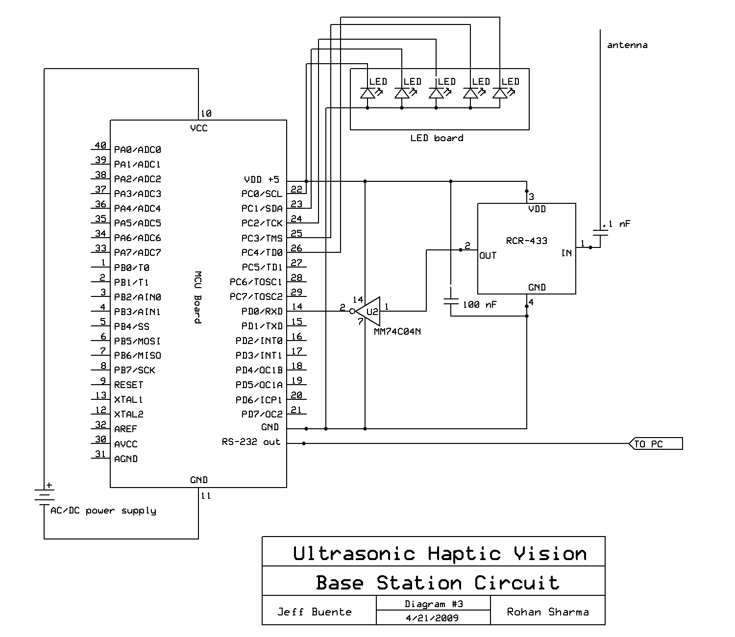
5. RCT-433/RCR-433, MM74C04N RF Circuitry
The RCT-433 is an RF transmitter running at 433 MHz which takes an inverted input from the MM74C04N inverter and transmits the signal over an attached antenna. The UART0 port on the microcontroller was used to send and receive RF data from the chips and since this port follows RS-232 protocol, a low represents a logical high on the input. Thus, the signal had to be inverted to correctly represent the data sent from the transmitter. The RCR-433 is the corresponding RF receiver running at 433 MHz, with the output of this chip inverted by the 04N before being input to the microcontroller. The inversion at the receiver end follows similar reasoning as above.

RF Receiver Circuit - RCR-433
6. Hardware Construction
The EZ1 sensor was mounted on a small piece of wood using screws which were connected to some sort of tube through an L-bracket, we were able to scrounge in the lab. This tube was glued on top of the motor gear so that the sensor turned with the motor. A contact switch was created so that the motor would rotate or sweep through the desired angle no matter the position of the motor on start up. This was done by gluing a wire sticking up from the hat and then gluing one sticking down from the piece of wood that the sensor was mounted on which moves with the motor. This was done in such a way that the two wires are in contact in the desired starting position of the motor which was the farthest angle read in the counterclockwise direction. A sweep of -135 degrees to +135 degrees was used in our design because we intended to have 7 motors each 45 degrees away from each other. Thus, the two wires that make up the switch are in contact when the motor is at approximately -135 degrees. The motor was also mounted in the hardhat by screwing it into the top of the hat and drilling a hole in the middle for the gear to protrude from the top of the hat, so the sensor could be mounted on it. More holes were drilled in the hat so that various wires could enter and exit as cleanly as possible, and also made it a bit safer, so that everything was contained in the hat and away from the user as much as possible. The hardhat has an insert in it that keeps the users head away from the top of the hat giving us room to mount the motor in the top. The insert also has a padded front that is in contact with the users forehead. This padded front was perfect for mounted the vibrators inside because it keeps the padding between the user and the vibrators which makes it more comfortable. The weight on the top of the tiny DC motor vibrators which enables them to vibrate was out in the open, and if put in an enclosed space the motor will not turn because the weight gets stuck and thus the motor will not vibrate. To fix this, the motors were encased in hollow cylindrical pieces of aluminum which were fashioned by hand out of a sheet of aluminum. With this quick fix the motors vibrated perfectly inside of the padded insert in the hat and were simply taped in to keep them in place. All of the wires coming out of the hat were taped to keep them together and all of the wires in the hat were taped to various parts of the hat or the insert, for the vibrators, so that there were no dangling wires inside to get caught on anything. The rest of the mobile circuitry is inside of a plastic case aside from all of the necessary batteries which are taped to the outside because they are so big. Inside of the case is the mobile MCU board which is powered by a 9V battery. It also contains the motor driving circuit board which is made up of the L298 along with a few simple circuit elements and is powered by a 9V battery through the LM340T5 5V regulator and controlled by outputs from the MCU. Next in the case is the ULN2803 which powers the vibrating motors using two AA batteries in series and controlled by outputs from the MCU. Finally the case contains the RF transmitter circuitry so as to transmit the sensory data obtained from the users surroundings back to the base and ultimately a PC connected to it. This involves a board with an inverter chip and a board specifically designed to hold the RCT-433 RF transmitter module, as well as an antenna that had to stick out of the case in order for the signal to be transferred. The base station contained little circuitry, having an MCU board with a Max233 for RS-232 connections to the computer, a RCR-433 board and inverter board for receiving the RF packets from the transmitter on the mobile board and a led board to denote the current state of the vibrating motors on the hat, indicating whether they are on or off. Overall the hardware in this project took the majority of time with the mounting and testing as well as the verification that it would work as intended. Even waiting for the hardware slowed the progress of this project significantly.
Receiver End Hardware
7. Design Mistakes
Our initial design consisted of using piezoelectric buzzers to implement the vibrating feedback to the user, which was based on a presumption that the vibration of these would be enough to provide significant haptic feedback to the user. This idea was based on a recommendation to use these elements. Unfortunately, these turned out to not fit the application we needed them for. They mainly generated sound and were only able to vibrate a small amount, which was not nearly enough for our application. Unless we assumed the users sense of touch was super sensitive these buzzers were not going to work. Unfortunately this took us two weeks to determine because we had ordered buzzers in the first week of final projects but did not receive them for a week and a half. Thus we decided to order mini DC vibrating motors for use as the vibrating feedback in our design and ordered them in the next possible order. We decided to try a different vendor because the last one had taken a very long time, so we ordered from BG micro instead. Unfortunately this was a big mistake as the shipment did not come before the end of final projects and was thus useless. We determined that our parts would not be arriving until a few days before final projects were due, and we had finished everything else besides the vibrating feedback for a good number of days. Thus, we decided to go to RadioShack to get the motors because we needed them immediately, despite the inflated price. Unfortunately, they only had 5 motors (between Ithaca and Cortland) and not the 7 our original design called for and we had no choice but to design it with the 5 motors.
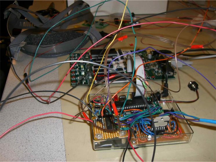
Hardware Construction Phase. Full of wires.
Software Design
Transmission End | Receiver End | Matlab Program
The software design for our system was implemented using a modular approach on both the transmitter and receiver sides of the system because of its efficiency and ease of implementation. However, we implemented 2 kinds of execution synchronizations on either side of the system. The transmitter side of the system (or the Hat from now) was synchronized using time counters. Each module in the Hat executed after a predetermined specific interval of time using a base clock as a reference (that was implemented using a timer). The receiver side of the system operated completely asynchronously and its execution was dependent on the reception of RF packets with a particular transmission id.
The following paragraphs provide a brief description of the various software modules that were implemented on both the sides of the system.
Transmission End or THE HAT
The transmission end of the system was the most prominent part of our project. It was responsible for range detection of the objects around a person, control of the movement of sensor on top of the hat, controlling the intensity of vibration at particular angles and for transmitting range data to the receiver end of the project. The following sequence diagram portrays the execution sequence of the various modules on the hat.
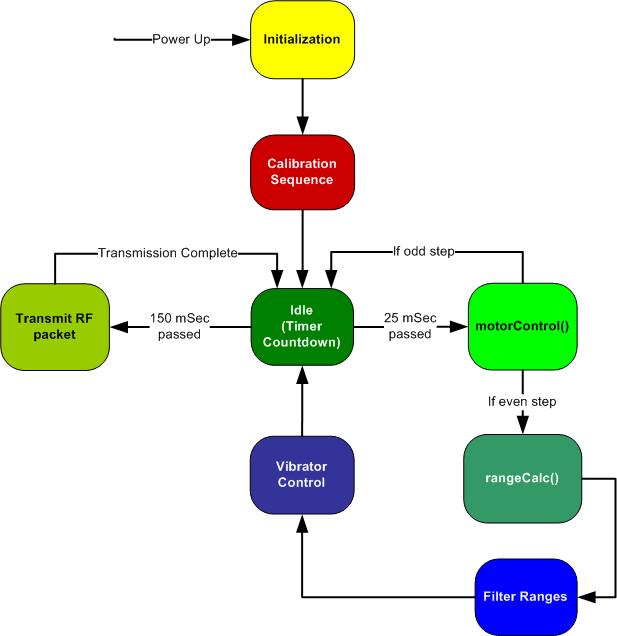
Software Execution Sequence on Transmission End
The following is a description of some of the important components that were implemented on the transmission end.
Stepper Motor Controller
The stepper motor controller module was responsible for generating control signals to move the attached bipolar stepper motor in 7.5o steps in either clockwise or counter clockwise. The control signals that were used to rotate the motor followed a simple state machine as can be observed in the software coding. A count of the number of steps was kept to keep track of the number of rotations of the motor. Since the motor moved in 7.5o steps, a 360 degree rotation of the motor could be achieved by moving 48 steps. However, since we were implementing a sweep of 270 degrees of our ultrasonic sensor, we only required the motor to move 36 steps in either direction. Thus after every 36 steps, the rotation of the motor was switched to the opposite direction. This stepper controller module was executed after every 25 mSec (milliseconds) and therefore, a complete motor rotation for a 270 degree sweep was obtained in 0.9 seconds.
Sensor Range Calculation Module
The range calculation module was responsible for reading the range input provided by the ultrasonic sensor at a particular angle. This software module could handle 2 kinds of inputs from the sensor: analog input or a PWM input.
For the analog input, the sensor outputted a voltage value to represent the range that it read at a particular point. 10 mV of this analog input represented 1 inch of range. Thus, an analog-to-digital converter was initialized and used to convert the analog input to a digital value. This was inserted as an extra option if ever there was a need to use the analog output.
The sensor also outputted a PWM signal, where the width of the signal (when the signal is a high) represented the range at a particular point. This was used as the main input for reading the range values at a particular angles as we felt that a PWM signal would be less susceptible to noise as compared to analog signal because of its digital nature. For this signal, 147 microSeconds represented 1 inch of range value. Our code implemented a 100 microSecond timer, where the Compare A Timer 0 ISR was called after every 100 microSec. This interrupt service routine was thus used to detect when the PWM signal input from the sensor went high and count the duration when the signal was high. A conversion factor was used to correct the calculated value as we were reading the signal every 100 microSec and a time of 147 microSec represented 1 inch. Thus, the calculated value was multiplied by (100/147) to obtain the correct value. The ISR was also used to indicate whether the PWM range that was being calculated was valid or not. Thus, whenever the rangeCalc() function was called, the valid value of the range was stored as the range at that particular angle.
This range function was called every 50 milliseconds so that the calculated range represented the range at every even angle. Thus, an array of 19 indices was used to store the range at particular angles.
Vibrator Motor Controller Module
The vibrator motor controller module was responsible for controlling the intensity of vibration of the motors at different angles, depending on the value of the range at that particular angle. Certain thresholds were set for changing the intensity of vibration of the motors. The motor starts to vibrate at a range of 5 feet and attains maximum vibration at 1 foot. We initially filtered the range at a particular angle by implementing an averaging filter and smoothing out the range values at a particular angle and the surrounding angles. This range was then checked against a set of threshold values to calculate the intensity of vibration of motors.
The filtering scheme that we adopted for obtaining the range values at a particular angle was a basic averaging filter. The range value at the angle corresponding to the vibrator motor and the immediate adjacent range values were taken and averaged out by multiplying the center range by 2 and adding it to the adjacent range values and dividing the entire sum by 4. This smoothened out the range at the angle and gave a better approximation of the distance to a nearby object. Thus, this value was compared against the threshold range values to set the intensity of the vibrator motors.
Once again, the 100 microSec ISR was used to generate the PWM signals for the vibrator motors. Initially, a 1 was outputted on all the motors which turned on the vibrator motors. Then depending on the intensity from (0-10), the output was switched to low or 0 to turn off the motor. Thus, a time period of 1 millisecond was implemented for each of the motors and the instances when the different motors were turned off were used to set the intensity of the various vibrator motors.
RF Transmission Module
The RF transmission module was responsible for forming the RF payload and transmitting the packet over RF using the RCT-433 chip. The RF packet was used to transmit 6 bytes of information which included the ranges at 3 angles, the direction of rotation, vibrator motor indication and the current angle of the motor. The RF packet is sent every 150 milliseconds, containing the last 3 range values calculated by the sensor. Thus, the ranges in the RF packet represent a sweep of 45 degrees.
UART0 is used to transmit packet over RF. A byte is written to the UART0 data register, which transmits the byte over the RS-232 connection to the transmitter chip RCT-433. This value is inverted by an external inverter because a 0 is used to represent a logic high according to the RS-232 connection. Thus an inverted value is used to transmit so that the transmitter chip remains turned off between 2 consecutive transmissions.
We used the Wireless protocol defined by Meghan Desai to transmit the RF packet, for which the link is provided in the reference section. However, the RF protocol code provided by Meghan Desai was for a Mega32. Thus, the entire code needed to be transported to the Mega644 format to actually make it work. Another issue that we encountered with the protocol was that it provided encoding for characters up to 15 bytes and since we used bytes with greater values than 15, we had to remove the encoding and decoding part from the wireless protocol to enable the correct transmission and reception of our RF packets. The wireless protocol code is provided in the appendices for reference.
Initial Calibration
An initial calibration sequence was also implemented to correctly position the stepper motor for performing 270 degree sweeps. An external contact switch was implemented as described in the hardware section. Thus the initial calibration sequence required the motor to move in the counter clockwise direction until it made contact with the switch. The interrupt service routine was used to keep a track of the input from the contact switch. As soon as the calibration input went high, it indicated that the motor had made contact with the switch and was at the correct position. At this point, the motor was initialized to the correct settings and the normal execution of the program started.
Receiver End
The receiver end of the system was very straightforward and easy to implement. As mentioned before, the receiver end executed asynchronously and was dependent on correct reception of the RF packets. Thus, the receiver only consisted of the RF module that received packets over the UART0 connection. The RF packets are once again received using the Wireless Protocol provided by Meghan Desai.
When a packet is received over RF, its decoded by the receiver end and its transmission id is checked for consistency. If the correct RF packet is received over RF, then it is decoded for the range values, direction of rotation, angles and vibrator motor indication.
The vibrator motor indication is sent as a single byte and the bits represent the vibrator motors that are currently vibrating at a certain threshold at the transmitter end. Thus, using this indication byte, the particular LEDs representing the motors are turned on the led board that is attached to the receiver MCU.
The range values along with the angles that represent that range are sent over RS-232 to Matlab running on PC, where they are plotted on a polar plot based on the angles sent to the PC.
Matlab Program
The matlab function toChiprev.m is a simple program that opens a connection to COM port 1 with a baud rate of 4800, to which the receiver MCU is connected. This program polls the COM port continuously and takes input of the form [(angle+300) (range)]. The angle value is added to 300 because the max range value is 255, which makes it easier to distinguish angles from range values when continuous values are being buffered. The range is then inserted into the array that is to be plotted to the corresponding location on a polar plot based on the angle value provided. This function forces matlab to update the plot every time it reads a new value so it is updated in real time.
Results
Testing | Test Results | Speed of Execution | Accuracy | Safety | Interference | Usability
Testing
We extensive tested the software and hardware of our project since the motion of the user depended on the correctness of the feedback provided by the vibrator motors in the hat. We performed various tests on the transmitter end of our project (the hat). Some of these tests are listed as follows:
- Following the intensity of vibration of the vibrator motors by standing close to a wall and rotating in place
- Following the increase or decrease in vibration as a person slowly approaches or moves away from a wall or a large object
- Walking down a hallway blind folded, without bumping into the walls
- Finding the center of minimum vibration when the person is disoriented and off center (by rotating the person several times)
- Obstacle Course: Placing various people at random locations and asking the user to navigate through them
Others hardware tests were also conducted to test the strength of the connections of the wires and to check the possibility of getting injured by the extensive hardware that a person has to carry during the demonstration.
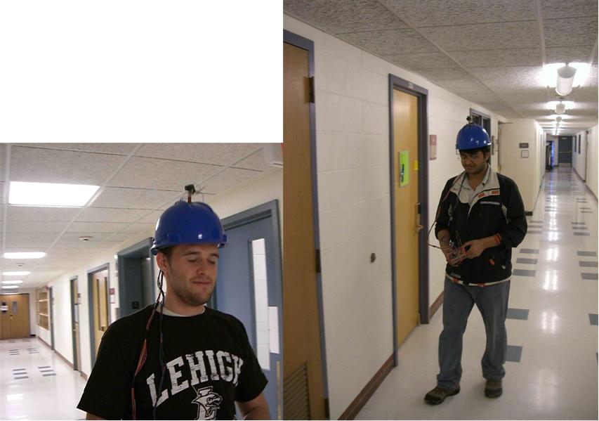
Testing 1 2 3. Testing THE ULTRASONIC HAPTIC VISION
Test Results
The result of the tests conducted above turned out to be quite satisfying. The vibrator motors smoothly changes vibration from one motor to another as a person rotates on the spot. We were able to transfer the vibration between the motors at one end to the other end with ease by rotating in place close to a wall. We also observed a smooth increase in vibration transition as a person approaches a wall and we set the motors to vibrate sufficiently hard when a person is about to hit a wall. However, some problems were experienced while observing the vibration transition of the motors. As mentioned before, we calculated erratic changes in range values from one rotation to the other which might be due to the noisy environment created by the stepper motor or might be due to the sensor itself. The sensor might be reading previously generated ultrasonic waves. Regardless of origin of error, the extreme changes in ranges would result in unexpected vibrations from the motor. Even after filtering the range values, the error in the ranges did not completely disappear.
For subsequent tests, we observed very good and accurate results. Several rounds of tests were conducted by both of us to ascertain whether a person could walk down a hallway blindfolded. We were both successfully able to navigate the hallway and avoid any major obstacles, even if a person were to suddenly stand in front of you. The sensor was able to detect the change in range due to the sudden appearance of the object during the sweep and provide the corresponding vibration at the angle.
The following is a sample plot that we obtained while running our tests:

Sample 2D User Range Plot
The 90 degree angle represents the forward angle of the angle user wearing the hat. As can be observed from the plot, there is an obstacle to the right and to the upper left of the user. These readings were consistent with the obstacles that we placed around the user during the test.
Speed of Execution
The ultrasonic haptic vision system was tested extensively and although it was not perfect it worked very well. The main limitation of this project was speed. The sensor could only output readings every 50ms (or at 20 Hz) and so the motor could only move that fast between every reading. Thus since the motor had a 7.5 degree step size we were able to update the sensory data by moving the motor every 25 ms and reading the range value for every other angle. This also raised some issues regarding the range readings that we obtained from the Ultrasonic sensor. Since the motor is moving faster than the sensor is able to output values, the range is obtained over a sweep and might not be consistent for a particular angle. Thus, we observed erratic spikes in the range readings around 2 adjacent points. To resolve this, we implemented an averaging filter to smoothen out the values and obtain a better reading.
Accuracy
High accuracy was not a major issue in this project. It was required that we get consistent and approximate values for the ranges and they increase and decrease with a smooth transition but we did not require the range to be accurate to the inch because an error of a couple of inches for a long range was not a big issue. The idea was to obtain a general location of the object at a distance and start vibrating the motors. Similarly, it was not important that we transmit the entire RF packet from the transmitter to the receiver. Since the RF data is generated on a real time basis and the Matlab polar plot represents the current location of the user wearing the hat, resending dropped packets would create a large delay in the execution of the program and lead to a delayed response in the representation of the user on the graph. Thus, we did not guarantee packet delivery to the receiver.
Safety
Safety is a major issue in this project because this project was designed with the intention that anyone could use it. We had no choice but to put the rotating sensor on top of the hat because of budgetary constraints, which was the only major safety problem. This is the first thing that would be removed in subsequent designs. Besides this, there is not much to be concerned with safety-wise. We made sure to tape all of the wires to the hat and have them come out in a taped strand to make the wiring as clean and safe as possible. Also, all of the electrical components other than batteries, which have to be frequently replaced, were kept inside a plastic case so that the user could not come in contact with any of the circuitry, making it very safe. The only problem with the plastic case design is that we had to have the L298 with attached homemade heatsink protruding from the top because it gets too hot to be contained in the case. Also, it would probably melt some of our circuitry if we kept it inside. This is another safety hazard which should be fixed in subsequent designs, most likely with a heatsink that would not cut someone.
Interference
There was plenty of interference in the lab in the 433MHz band as many groups were using the same RF transmitter and receiver chips as we did. This caused many lost packets which resulted in sparse updates to the matlab function running on the PC at times. There was no way around this because of all of the RF noise in the room. The other packets did not cause any data corruption or false data because we read only the ones we had sent from the transmitter as denoted by the session ID number in the packet. Unfortunately this noise was unavoidable and surely many groups found this as an issue.
Usability
Usability is the high point of this project. This design was intended for use by anyone barring safety concerns because of the rotating sensor on the top. This project was designed primarily for the vision impaired. We wanted to create a project specifically for people with special needs. The intention of this project was to be usable by anyone with minimal training if at all. The user should be able to intuitively feel objects around them by just putting the hat on, and letting the haptic interface do the rest.
Conclusions
Design Analysis | Applicable Standards | IP Considerations | Ethical Considerations | Legal Considerations
Design Analysis
The final design met and exceeded all of the expectations that were laid out before starting to construction of this project. The whole goal was to be able to navigate a hallway successfully without running into any walls while blindfolded as a demonstration that this idea was intuitive and feasible. Next time, barring any budgetary constraints we would have attached motors all around the hat in order to get as much sensory data through haptic feedback as possible with about 8 vibrating motors. Also, the rotating ultrasonic sensor atop the motor mounted on the hat is undesirable because it is best not to have a delicate rotating component for safety and aesthetic concerns. Two solutions to this would be to have different EZ1 sensors for each of the 8 vibrating motors which would enable them to be updated at 20Hz and thus a more effective filter could be used because of the fast measurements. Another option would be to have one ultrasonic transmitter that transmits radially, with 8 ultrasonic sensors that read the input from the transmitter to determine distances, but this option would have involved much more hardware because we would have had to generate the range value from the ultrasonic sensor ourselves as opposed to using the EZ1 to do all of the interpretation for you.

Life after 5 continuous weeks in lab. Working hard.
Applicable Standards
The only standard that we used in the project is the RS-232-C defined by the Electronics Industries Association (EIA) for RS-232 communication with between the receiver end of the system and the Matlab program on PC. We didnt implement this standard ourselves but merely used the UART which already utilizes this standard.
Intellectual Property Considerations
This project was based on an idea formulated by graduate students at the University of Tokyo. We credit them with the original idea but we did not copy their design, creating a unique design of our own and thus no intellectual property rights were infringed upon. We do not believe that this project brings to light any patent opportunities because it is far too bulky and awkward with the rotating motor on top to be of real use to consumers at such. This topic could be discussed on a serious level if this project was taken a step further and redesigned. There are most likely publishing opportunities for this project because it is a very interesting idea and the fact that the final product works so well.
Another topic where we had to consider intellectual property was during the use of the Wireless protocol by Meghan Desai. We credit her with coming up with the wireless protocol for synchronizing the transmission between the transmitter and receiver and for setting the sequence of bytes that were required to be transferred from the transmitter to the receiver. Thus, we used her intellectual property and modified it to execute efficiently on the ATMega644.
Ethical Considerations
We strongly followed a code of ethics in designing and creating this project. We followed no strict safety standards but tried as hard as possible to make this project as safe as possible for the potential user and all those around them. Obviously, since this is a prototype project and not intended to be marketed and sold to the public there are some parts which are not safe enough for public use. One such part is the rotating portion of the top of the hat. This creates some concerns as it can wrap something around it, can injure someone if the hat falls off because it is basically a small wood board protruding from the top. This is not recommended for general use at this time. We always maintained honesty when stating claims about our project and what it could do. Our goal was to be able to navigate a hallway blindfolded using only our project and we believe that this goal has been achieved after extensive testing which we back 100%. We also never claimed that our sensor was perfect as it actually gets some strange values at times turning vibrators on and off randomly which we were not able to totally filter out due to the nature of the design. Although this is intermittent, it limits the speed at which the user can move around because of some bogus outputs. The ultimate purpose of this project was to improve the understanding of technology in that we wanted to explore how this use of haptic feedback can be a very intuitive and user-friendly interface in linking human senses to technology in order to provide the user with information. At all times we accept and even encourage honest criticism of our work on this project. We understand its limitations and imperfections but tried our best on this work, so any honest criticisms would only teach us about any mistakes we may have made or things we may have overlooked which can only benefit us in the future. We always credit those for which credit is due with respect to any ideas or actual code or even hardware designs we used in this project. We have stated exactly what we borrowed and credited the owner(s) in the Program/Hardware design section. At all times we made sure not to disrupt or touch any other groups property that was left in the lab. It is also important to note that anytime we were requesting samples we did not lie about our project or the fact that we were students in order to get free parts because of ethical considerations. We always supported our classmates even though we are competing against them for this project grade. We enjoy seeing other projects and the interesting designs and ideas of other groups and went about this competition in an ethical and professional manner. One group who was using the same chip as in our design could not get it to work at some point and asked for our assistance because we had successfully used this chip already. We heartily agreed and helped this group to debug their problem even though it took away from our own time because we strongly support our colleges regardless of the situation. We are all just trying to survive this class and most importantly this final project.
Legal considerations
The only legal considerations that apply to this project are with respect to the transmission of RF packets at 433 MHz. The FCC rule is that the radiated power must be less than 1 watt for an unlicensed transmitter at this frequency. This circuit draws only 5mA at 5V which means it dissipates only 25mW and thus cannot transmit more than 25mW which is much less than the FCC requirement.
Appendix
Parts List | Task Allocations | References | Source Code | Schematics | Project Pictures
Budget and Parts List
The following is the parts list, detailing the parts that we used in our project. We are very grateful for the generous contribution of Maxbotix of providing us with a sample of their Ultrasonic Range Finder. Without their help, we would not have been able to complete our project, incorporating the extra features, and remain under budget.
Parts List:
|
Part Name |
Manufacturer |
Part Number |
Qty |
Unit Price |
Cost |
Acquire Method |
|
Ultrasonic Range Finder |
Maxbotix |
LV-EZ1 |
1 |
24.95 |
|
Sampled |
|
Maxim dual RS232 I/F |
Maxim |
MAX233CPP |
1 |
7.00 |
|
Sampled |
|
Mega644 microcontroller |
Atmel |
ATMEGA644 |
2 |
8.00 |
8.00 |
Sampled 1, Purchased 1 |
|
Vibrator Motors |
RadioShack |
273-107 |
5 |
0.99 |
4.95 |
Purchased |
|
Stepper Motor |
Jameco |
171601 |
1 |
2.95 |
2.95 |
Purchased |
|
9V Battery |
Duracell |
|
2 |
2.00 |
4.00 |
Purchased |
|
9V Battery Clip |
Keystone Elec |
84-6k-ND |
1 |
0.57 |
0.57 |
Lab Stock |
|
Small Solder Board |
|
|
3 |
1.00 |
3.00 |
Lab Stock |
|
Freescale Solder Board |
Freescale |
|
1 |
Free |
|
Sampled |
|
Freescale Power module |
Freescale |
|
1 |
Free |
|
Sampled |
|
Dual Full Bridge |
STMicroelec |
L298HN |
1 |
4.93 |
|
Sampled |
|
5V Reg - Higher Amps |
|
LM340-T5 |
1 |
1.00 |
1.00 |
Lab Stock |
|
Custom PC board |
|
|
2 |
4.00 |
8.00 |
Lab Stock |
|
DIP socket |
|
|
3 |
0.50 |
1.50 |
Lab Stock |
|
Header Pins |
|
|
24 |
0.05 |
1.20 |
Lab Stock |
|
RS232 DB9 Connector |
Tyco Elec |
A2100-ND |
1 |
2.00 |
2.00 |
Lab Stock |
|
RS232 Connector wire |
|
|
1 |
1.00 |
1.00 |
Lab Stock |
|
Power Supply |
|
|
1 |
5.00 |
5.00 |
Lab Stock |
|
RF Transmitter |
Radiotronix |
RCT - 433 |
1 |
4.00 |
4.00 |
Lab Stock |
|
RF Receiver |
Radiotronix |
RCR - 433 |
1 |
4.00 |
4.00 |
Lab Stock |
|
Machine Pins |
|
|
100 |
0.05 |
5.00 |
Lab Stock |
|
Blue Hard Hat |
|
|
|
|
|
Owned |
|
Materials for sensor mount |
|
|
|
|
|
Salvaged |
|
Transmitter Unit Box |
|
|
|
|
|
Salvaged |
|
Inverters |
|
MM74C04N |
2 |
1.00 |
2.00 |
Lab Stock |
|
Darlington Array |
T.I. |
ULN2803AN |
|
|
|
Sampled |
|
|
|
|
|
Total Price |
$ 58.17 |
|
Task Allocations
Software:
- MCU code for both mobile and base stations Rohan
- RF Encoding and Transmission Test Rohan
- Matlab Code on PC Jeff
Hardware:
- Schematic Design Jeff
- Logical Structure - Rohan
- Soldered MCU boards Both
- Soldered controller boards boards, wires, etc Both
- Constructed hat, mounted motors and wired it all up Both
- Mounted hardware in plastic case and wired it Both
- Made heatsink, vibrating motor casings Jeff
- RF Hardware Rohan
- Hardware Testing Both
Documentation & Parts:
- Ordering and Sampling Parts Both
- Final Lab Report Both
- Web Page - Rohan
References
Data sheets
- Ultrasonic Sensor - MaxBotix LV-EZ1
- Atmel Mega644 Microcontroller
- L289HN (Dual Full Bridge)
- ULN2803 (Darlington Array)
- RCT-433 (RF transmitter)
- RCR-433 (RF receiver)
- Protoboard for Mega644
Vendor Sites
Code/ Design Borrowed from others
- Wireless Protocol by Meghan Desai
- PC Control & Temperature Monitoring Project
- Design by Graduate Students in University of Tokyo
Source Code
Schematics
- Motor Driving Schematic
- Mobile/Hat/Transmitter End Schematic
- Base Station / Receiver End Schematic
- MCU Protoboard Schematic
Project Pictures