Touchpad/Infrared Music Synthesizer
"Generate music with your laptop touchpad!"
Wei-jiunn (Vic) JangKalina Jordanova
The Touchpad Infrared Music Synthesizer uses a laptop touchpad and an infrared distance sensor to control tone, volume and decay length of musical notes. Operating in one of six modes, this device offers a variety of options for generating musical tones. Operation is simple - a user can produce interesting music by as little as swiping a finger. The Touchpad Infrared Music Synthesizer was created to illustrate a fun approach for music generation.
High Level Design
Rationale
The initial concept of our project was to create a musical instrument, similar to the Theremin, which could control various sound characteristics through a three dimensional user interface. Initially, we liked the idea of creating an instrument that would have three axes of variability, so that we could control more parameters than just the pitch and volume controls of the Theremin. We decided to use a touchpad and a distance sensor to control music qualities. We believed that the touchpad, having output variability in two dimensions, could be especially useful in creating interesting ways to generate musical tones. We designated the distance sensor as the volume control.
Concept
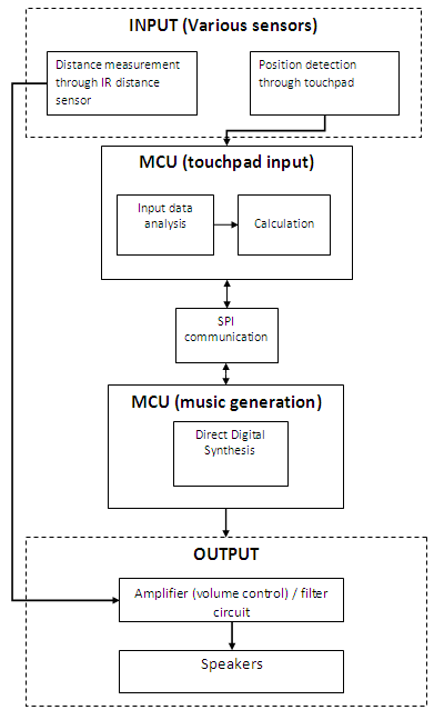
A laptop touchpad and a infrared distance sensor would be used to create music by a user. The touchpad would control different sound characteristics depending on which of six modes of play the instrument was currently in. Through an infrared sensor, the user also would have volume control over the sound being produced.
The six modes of play are: standard, chords, harmonics, double harmonics, decaying harmonics, and sinusoidal sound. Upon restart, the default mode of play is standard mode, which consists of four octaves of individual notes that can be played according to touchpad positioning. The user selects a new mode by quickly gliding their finger across the touchpad in either the x or y direction.
Two ATmega644 MCUs were used to control the sound generation and touchpad interfacing. The MCUs communicate with each other through SPI communication. To generate sound, DDS was used by outputting values to a DAC0808 with a variable input reference voltage from the distance sensor. The Karplus-Strong plucked string algorithm was used to generate notes in all modes except for the sinusoidal mode.
Background Math
To create sound, we alternated between using the Karplus-Strong plucked string algorithm and generating pure sine waves.
Karplus-Strong plucked string synthesis algorithm is a well-known method to synthesize plucked string sound. It requires very few computations and can be done even when the computation ability is limited. The string sound is excited by white noise (which is essentially the same as impulse in terms of phase), and the decay speed and frequency can be controlled easily through modifying the length of the white noise and the decay factor.
The Karplus-Strong Algorithm is actually a low pass filter implemented using moving average digital filtering. To do this, we use an array of random numbers (representing white noise) which we output to the DAC0808. Each entry of the white noise array is first outputted to produce sound, and then replaced by the average of itself and the next entry. At the end of the white noise sequence, the process is repeated from the beginning. A decay factor inside the algorithm will make the amplitude of the sound smaller and smaller as time goes by and eventually dies out (as in the case of a plucked string).
In our project, we implemented methods modifying both the frequency and the decay speed. The length of the white noise is actually identical to the number of samples. For example, if the sample rate was 50us/sample, a white noise array with length 200 would generate a sound with period of 10 milliseconds (100Hz). The frequency can be calculated using the following equation:
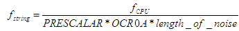
To generate the correct frequency, we first chose a set of values for the prescalar and OCR0A (prescalar=8 and OCR0A = 90), and did all of the calculations for the length of noise variable in excel for piano notes ranging from 2 octaves below middle C to 1 octave above middle C. These values were stored in data memory, which we could access in order to change the frequency of our note in real time, without doing additional computations. A detailed account of our Karplus-Strong implementation can be found in the Software section.
To generate sine waves, the value being output to the DAC was incremented through a stored sine table. Varying the frequency was achieved in either of two ways: by changing the increment of the sine table index, or by changing OCR0A (which controls the rate of the ISR). The frequencies of the sine waves being generated were calculated by:
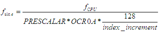
where fsine is the frequency of the sine wave, fCPU = 16MHz (for our crystal), PRESCALAR = 8, and OCR0A and the increment index were the parameters being changed by the user. For our sine wave mode implementation, the y-position was used to change the value of index_increment (from 1 to 15), and the x-position was used to increment OCR0A.
In order to ensure a reasonable sine wave, there must be at least 8 samples generated per period. For our sine generation, we decided to use a sine table array of length 128, thus, in order to generate the minimum of 8 samples per period, we were limited to an index increment value less than 16.
When sending information from the touchpad MCU to the sound generation MCU through SPI communication, we wanted to keep the number of bytes per packet to a minimum. Since the touchpad itself has x and y ranges up to 6000, we needed to scale the coordinates down when transmitting the information for sound generation.
Logical Structure
The core of our device is the touchpad interface. Initially, we wanted to use a touchpad produced by Adesso, but we found that the documentation was poor and decided to switch to a Synaptics device. We did not plan on using two MCUs, however we found that when using only one MCU the two intensive ISRs for sound generation and for reading the touchpad would override each other depending on which was executing faster at the time. Thus, we used two Mega644 with SPI communication to transmit information. Touchpad output was read through the first MCU, and sound was generated by the second MCU through a DAC and outputted to a set of speakers. Finally, the volume control was implemented purely in hardware, by a variable voltage output from the distance sensor.
Hardware/Software Tradeoffs
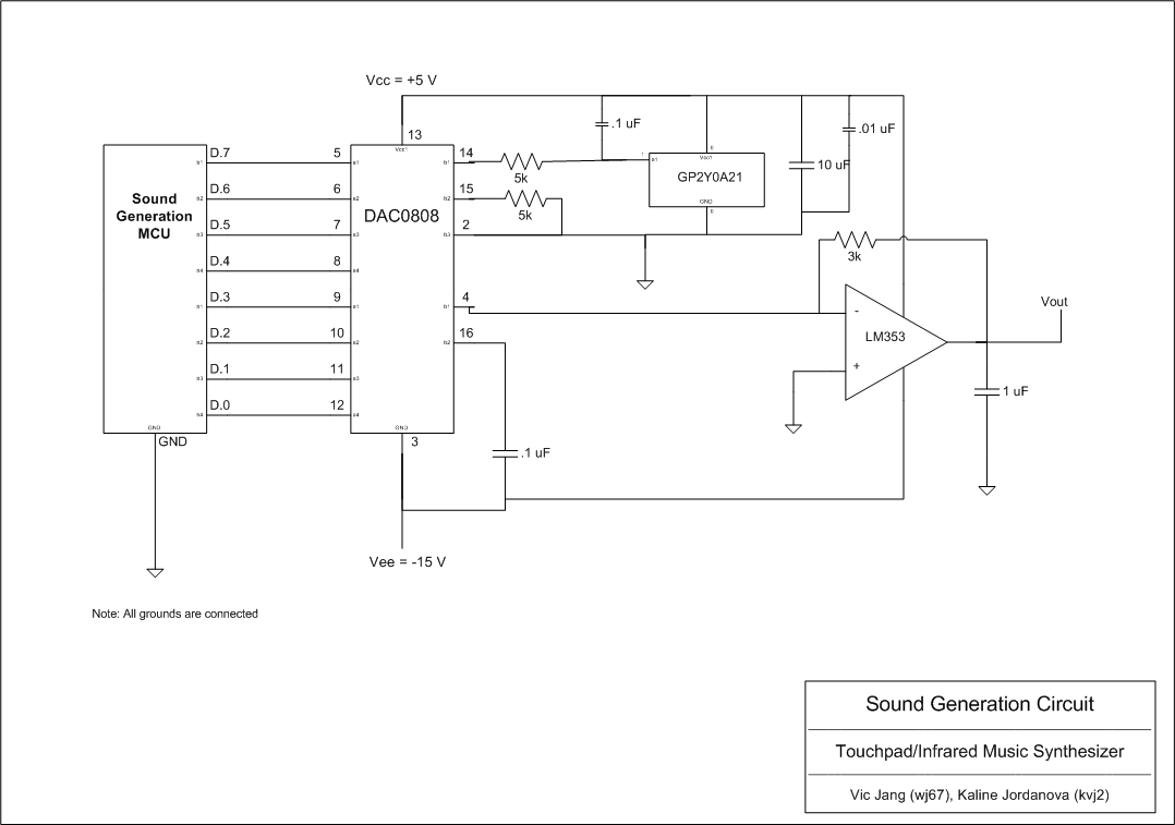
We decided to implement the distance sensor used for volume control solely through hardware. This saved us time for calculations in the sound generation MCU, which was already time-sensitive due to the sound ISR. We were able to do this hardware implementation fairly easily, since the sensor we used had a variable voltage output dependent on the distance being measured. With the sensors output voltage set as the reference voltage for a DAC0808 we were able to amplify the sound produced from the MCU based on the distance between the users hand and the sensor. Furthermore, the DAC0808 allowed us to control the maximum voltage of the sound wave through three resistor values of the circuit. Thus, based on the maximum output voltage from the distance sensor (~3V) and the resistors that were used, we were able to ensure that our output waveform would be no greater than 3 or 4 volts, thus ensuring that it would not clip.
Although implementing the volume control purely in hardware lessened some of the software processing, we found that the sensor generated a lot of noise when it was connected to the DAC0808 circuit. In order to keep the noise generated by the sensor low, we placed a couple of large capacitors (1 uF and 10 uF) to steady the output waveform.
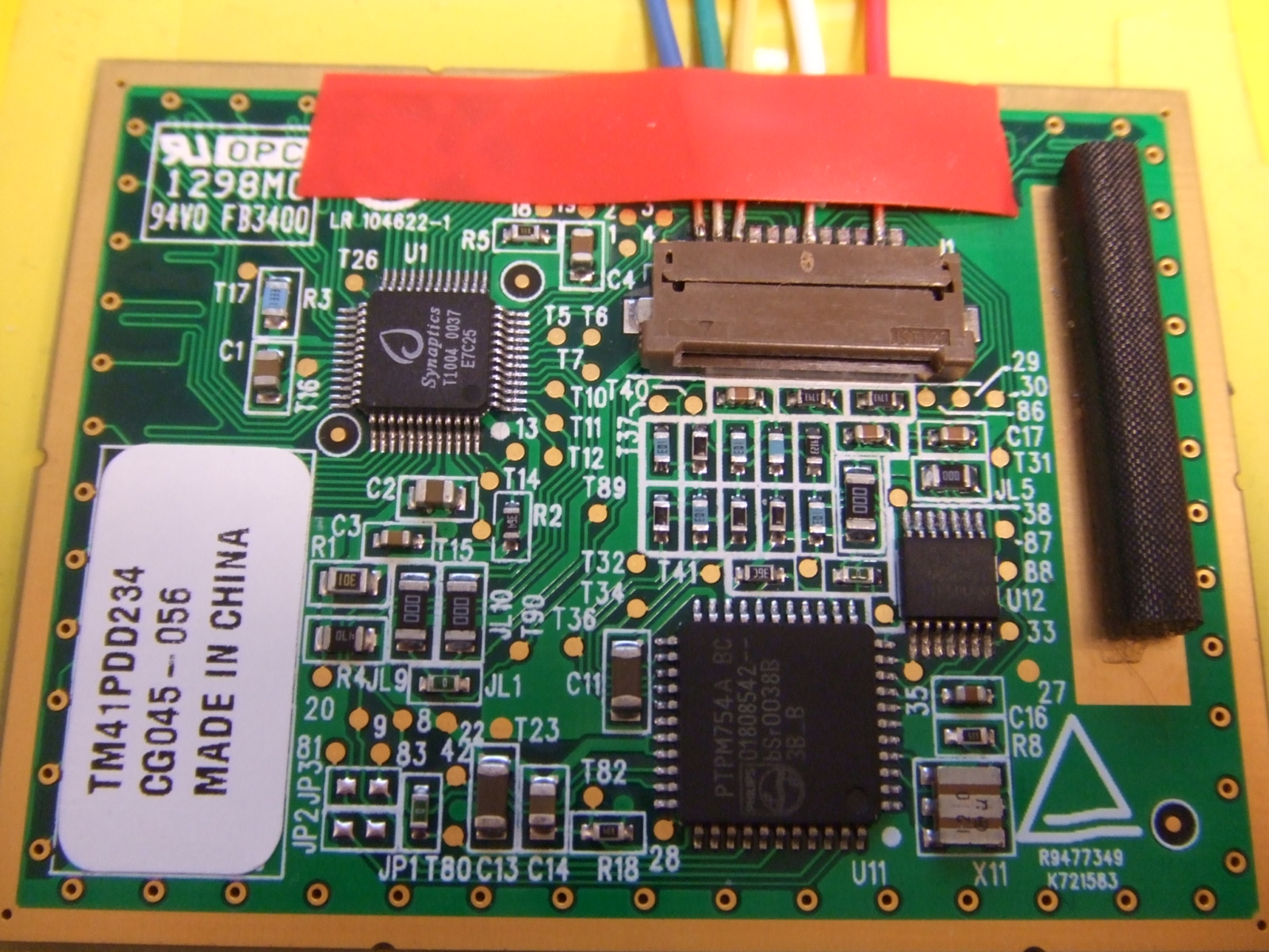
The PS/2 protocol indicates that PS/2 devices should have four input/output lines: Vcc, Gnd, Clock and Data. Since we found our touchpad in the junk box, we had to thoroughly examine the 12 output pins to determine which four were the ones important for data transmission. Once we had found the Vcc. Gnd, Data and Clock lines, we connected them as inputs to the CPUs. We also connected the lines through two npn BJTs such that we could pull them low or let them float high via two MCU output pins.
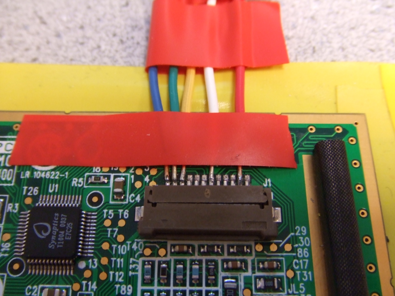
Green: DATA, Yellow: CLOCK, White: GND, Red: VCC, (Blue: not used)
Hardware Design
Hardware Details
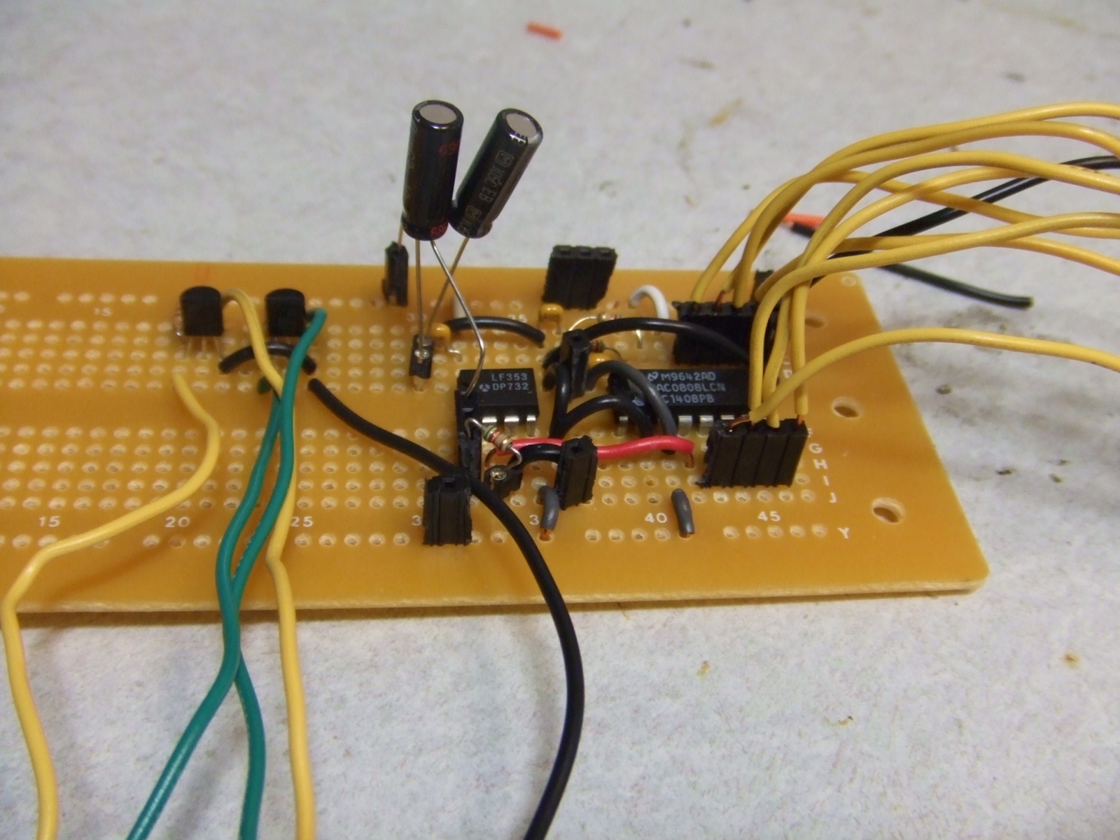
There were two basic circuit setups, one for each component of the project: the sound generation circuit and the touchpad circuit.
The sound amplification circuit uses a DAC0808 digital to analog converter and an LF353 op-amp sampled from the lab. In order to stabilize the circuitry, two large capacitors were added from the output to ground, and from Vcc to ground. The supply voltages on the DAC0808 were +5 V and -15 V, indicating that we needed to use an extra power supply for this circuit. We found that decreasing the supply voltage to -10 V caused clipping on the output waveform. Using 5K resistors throughout the circuit ensured that the output waveform's maximum amplitude did not exceed the maximum amplitude of the infrared sensor (measured to be about 3.1V at a distance of 4 cm).
Click for schematics
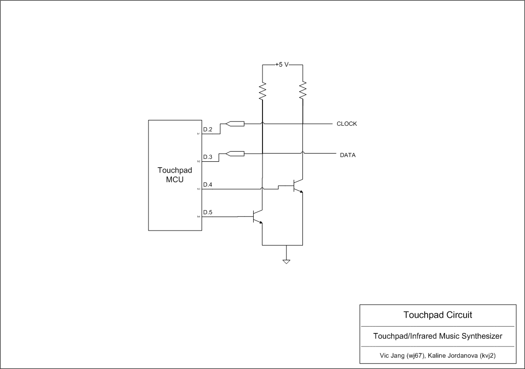
The Synaptics TM41PDD234 touchpad circuitry was straightforward once we figured out the pinout (through deductive logic and testing). Via two 2N 3904 npn BJTs and two 10k resistors, we were able to connect to the MCU through an input and an output port each, and could control and read data from the touchpad.
Click for schematics
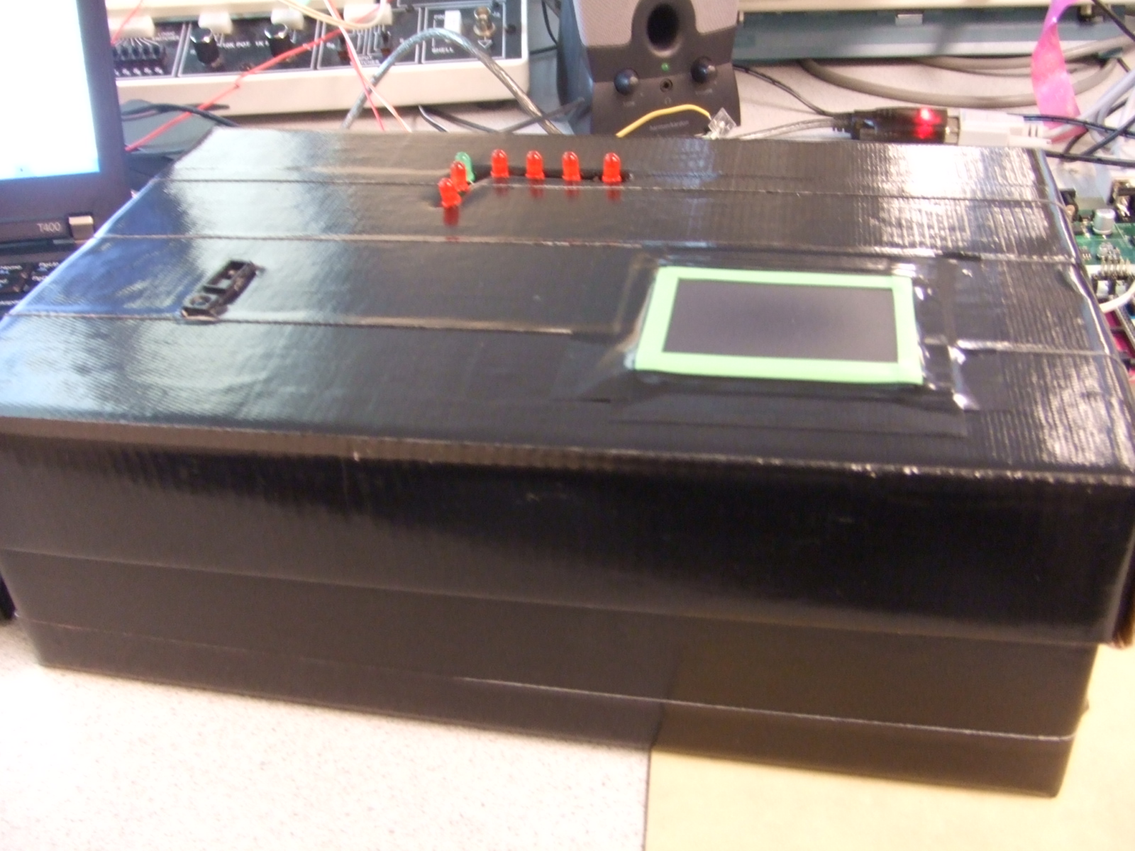
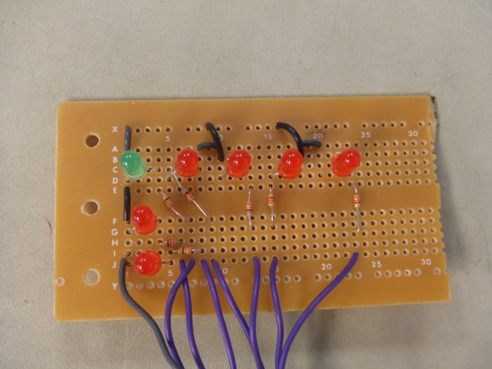
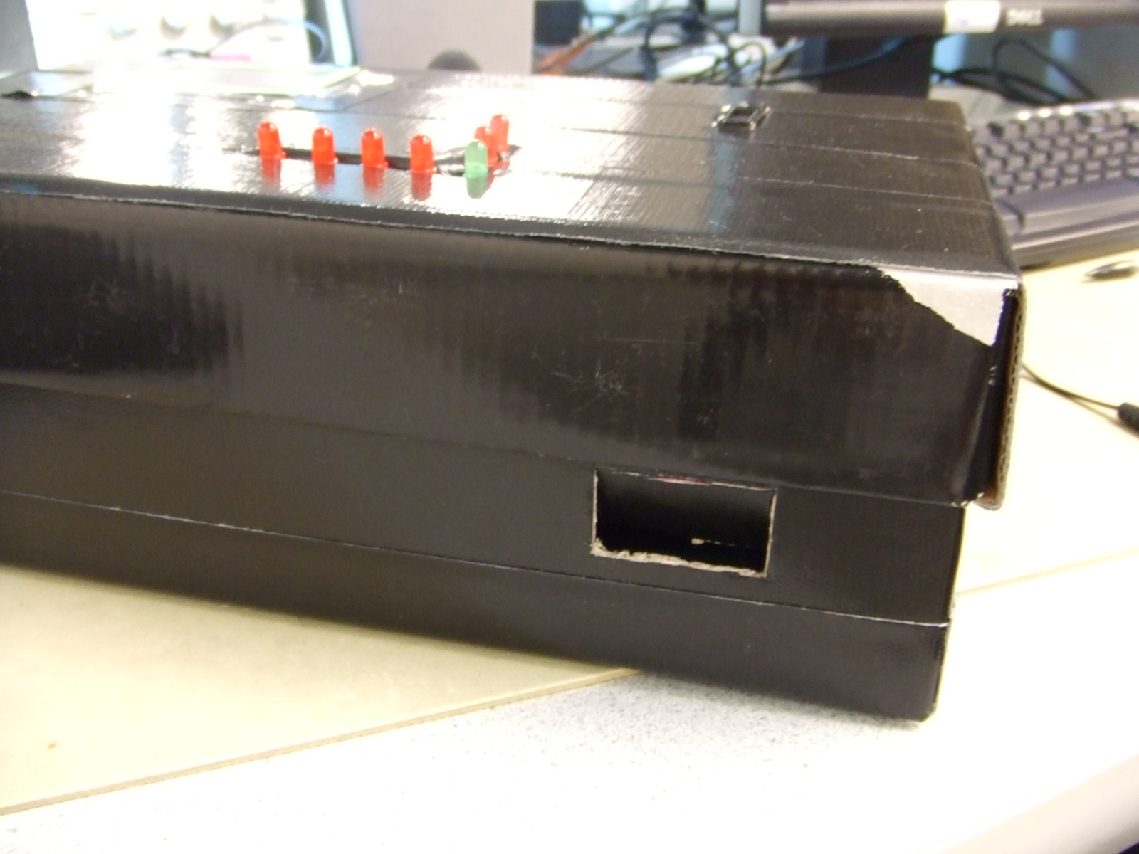
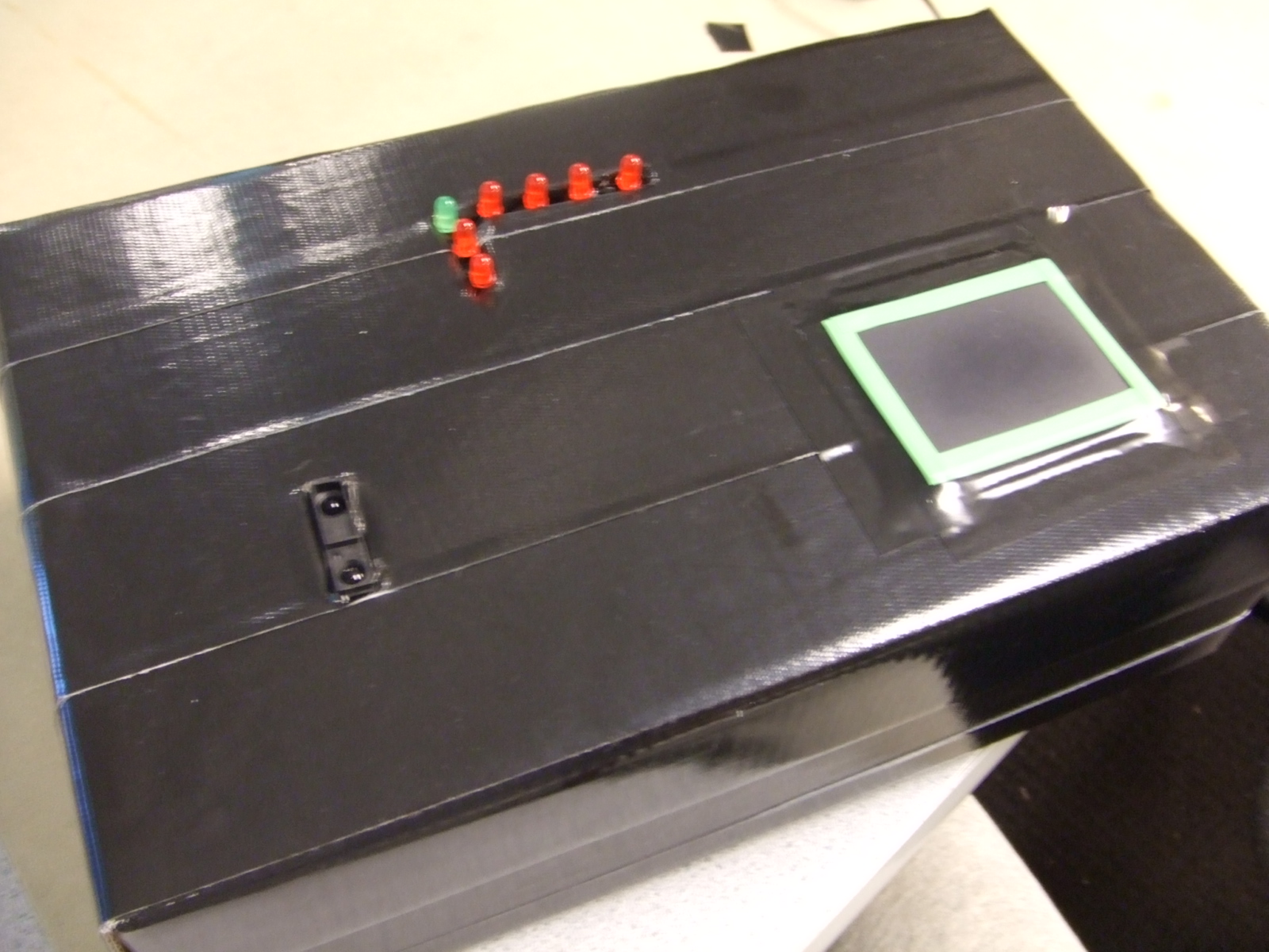
Finally, to display the mode we used a simple LED circuit. With seven LEDs, each connected to an output pin from the MCU through a 330 ohm resistor, the circuit was able to indicate the current mode, and whether we were in the standby period for changing modes.
Click for schematics
One very critical thing that we discovered was the importance of having noise-free SPI communication between devices. Initially, we were using two long blue jumper cables to connect the pins of PORTB of each MCU together (used for SPI). We did not get reliable communication, and eventually discovered it was due to noise on the cables. After changing the circuit to using only one, short cable, we were able to achieve SPI communication as expected.
Software Design
We have two .c files that we used to program each of the MCUs: sound-slave.c and touchpad-master.c.
- The sound generation file consists of:
- SPI communication through ISR
- Sound generation through ISR
- Updating wave generation
- The touchpad file consists of:
- Send to and Read from the touchpad through polling
- Read from the touchpad through ISR, with initialization and disabling
- Touchpad data update for SPI transmission
- SPI communication through polling
Touchpad
The PS/2 touchpad protocol specifies that a host device indicates its intent to send data by pulling the data line low. The touchpad will then pull the clock line low 11 times during which it is expected that the user will send a packet along the data line. If the touchpad wishes to transmit to an external device, it pulls the clock line low to signal the initial intent to transfer, and then 11 bits are transmitted. In order to implement this procedure, we used both polling and interrupts to synchronize the ATmega644 with the touchpad.
Upon initialization, a reset command was sent to the touchpad. In order to read absolute x- and y- coordinates along the touchpad, the device needed to be placed into absolute mode. Placing the touchpad in absolute mode also places it in streaming mode, with a default stream rate of 40 packets per second. In relative (remote) mode, sending data to and reading data from the touchpad can all be done through polling. However, in streaming mode, we found that setting up an interrupt was the best way to detect the initial clock pulse indicating the beginning of a transmission. Thus, for initialization and all commands we issue to the touchpad before we set it into absolute mode, we used the send() and read() polling functions. After setting the touchpad into absolute mode we used the interrupt to receive data.
In the basic absolute mode structure, the touchpad transmits six-byte data packets. To read these six-byte packets, an ISR is triggered at the beginning of the first byte. Once we have entered the ISR, we poll for the remaining bytes of the packet. We decided to implement the packet reading this way because we found that we could not rely on the ISR trigger for each data bit. Upon each data packet transmission, the program turns off the touchpad ISR, pulls the clock line of the touchpad low (inhibiting any further transfer attempts until the line is released) and enters a task which calculates the relevant x, y and z (for pressure) values depending on the current mode of the device. Then, these values, along with the mode that the touchpad is in, are sent to the sound generation MCU. After the data has been successfully received by the sound MCU the ISR is reset and touchpad data can be received.
To change the mode, a user presses down on the center of the touchpad for about 450 ms, after which an indicator LED will turn on, signifying that the mode is ready to be changed. Then, swiping a finger in either the x or y direction will result in a mode change whenever possible. Some x-modes permanently disable the y-mode, thus a swipe in the y-direction will not result in a change in the y-mode. To implement this procedure for mode changing in our code, we created a mode state machine. This state machine checks to see the length of the touchpad press, and whether it is in the right range for a mode change. If this is the case, and LED will turn on, and the touchpad will wait for motion from the user. When a new position is recorded, if the change in position is above a certain threshold (determined through trial and error), the mode will change depending on the direction of the motion.
Since many of our modes used the Karplus-Strong plucked string algorithm, we decided that each tap would result in only one note generation. Thus, we needed to debounce the touchpad to prevent any unnecessary data transmissions to the sound generation MCU.
The touchpad and SPI protocols were the trickiest elements to implement. Initially, we had a lot of trouble with the touchpad ISR, and found that it was being triggered one extra time after each data packet. In order to suppress the extra trigger, which inevitably resulted in incorrect data packets, we inhibited the touchpad after we had received one packet, and before we were ready to receive another. According to the PS/2 protocol, the last bit that was triggering the ISR was suppressed by inhibiting the touchpad, and we were always synchronized with the ISR when we returned into our idle mode.
We also had a lot of trouble implementing the SPI communication with the other MCU. Due to the time-sensitive nature of the sound generation, which was implemented using an interrupt, we found that we would miss data bytes whenever we tried to transmit more than one byte at a time. To remedy the problem, we instilled an error checking system. When sending two data bytes, the first bit of the first byte is designated as 0, and the first bit of the second byte is designated as 1. If the sound MCU does not receive the bytes in this order, it will discard the data and wait for a resend from the touchpad MCU. The touchpad MCU, on the other hand, checks to see if it received the correct return SPDR values from the sound MCU (designated as 0x01 for the first bit and 0x02 for the second bit). Upon an error, the master MCU would resend to the slave. When testing this algorithm, we set up LEDs to display the second byte being received by each MCU, and we did indeed see that there were often wrong bytes received, but the MCUs quickly corrected themselves.
Finally, we found that we had some trouble with UART while implementing the touchpad file. Printing indicators out to hypertrm while polling for data bits proved to be too time consuming for the nature of the touchpad data transfer, so we quickly resorted to solely using LEDs for debugging.
Sound Generation
We started creating this code from the MATLAB file given in ECE 4760 page and tried to figure out how the plucked string algorithm actually works. In the Karplus-Strong Algorithm, normally we had to keep track of 2 indices for the 2 entries we are taking average of. In order to use less instructions in the ISR, we came up with a way to use only one index to keep track of the 2 entries. After testing, we observed that it did improve the speed of ISR, which helped us get a better range of frequency.
As discussed previously, to change the frequency of the string sound being generated, we had to change the length of the white noise array. The white noise was stored in a long array of length 256, which was actually a significant amount of data memory. Therefore, instead of having several different arrays of different lengths, we only had one array stored in memory, but would only use part of it depending on our output frequency. For example, if we were to generate a sound with noise length 120, we would reset both counters back to 0 whenever they reached 120. Every time we were about to play a new sound, the white noise array would be reloaded to its initial state. Instead of generating a new random sequence, we stored a string of random numbers inside an array which we never changed after initialization. This array was initially put in data memory, but later changed to program memory in order to cut down on the usage of data memory in this program. To construct the array, we generated 256 random numbers in excel having the same range as the rand() function in C store them in program memory upon declaration.
The other thing that we had the ability to modify to change the output sound frequency is the speed of the ISR. Through changing the value of OCR0A and the prescalar, the goal can be easily achieved. However, there is actually a limit for this idea. The fastest rate of ISR is limited to the runtime of the ISR itself. If it takes 50us for the ISR to run, then it the sound generation could never run faster than once every 50us. This was our upper limit for frequency.
The other limit of our implementation was the length of array. To have a low frequency sound, we could either let ISR run slowly or have a longer noise length. The length of the array was limited because it is directly related to the size of memory it's using. Furthermore, we were playing 3 notes together (a chord) in one of our modes of the synthesizer, and since the data type of the arrays were LONG we did not have space to afford larger arrays. Therefore, when we were playing sound at lower frequency, we doubled OCR0A so that we could get the same frequency with half the length of noise.
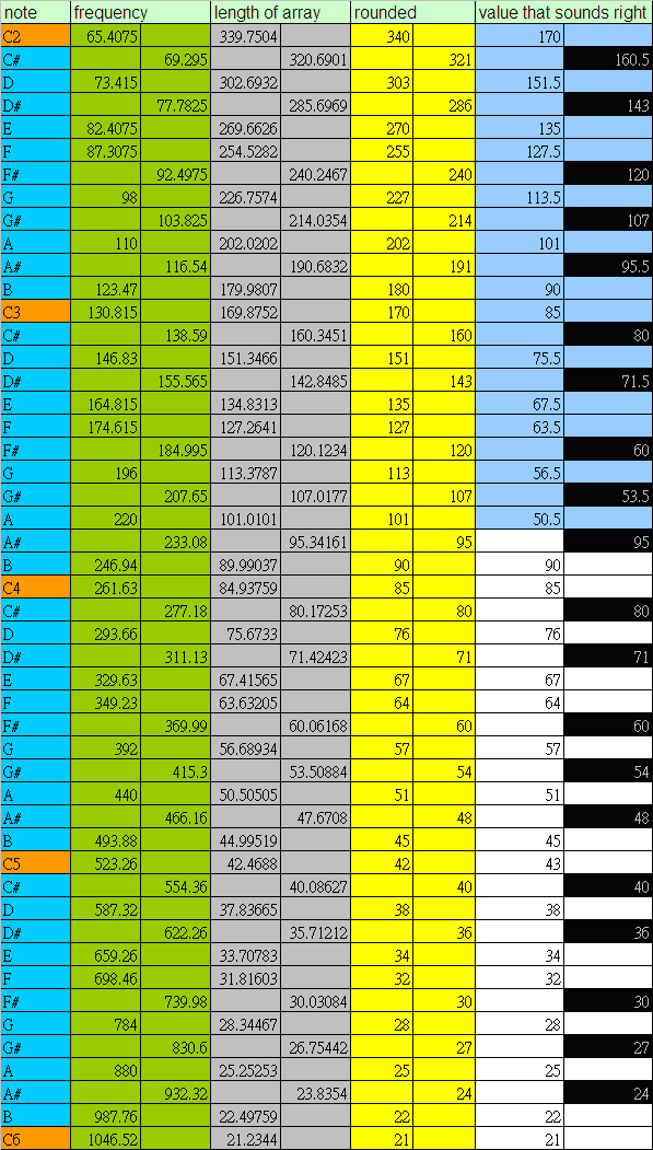
All the calculation for the length of noise and OCR0A were done in excel rather than in real time, the following table gives a rough idea of how we did it:
with OCR0A = 90 for the white part and OCR0A = 180 for the blue part.
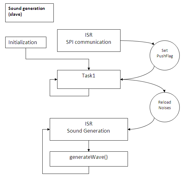
The logic flow of the sound generation slave program can be express as in the diagram above. The only trigger of the sound in this program is the ISR of SPI slave. When the ISR is triggered, it's equivalent to a button being pushed, so when this would happen we would set the flag PushFlag. Task1 is the only task in the main while(1) loop, which keeps scanning for the PushFlag == 1. Whenever PushFlag is equal to 1, it first stops the sound generation ISR, reloads the white noise, and then restarts the ISR. The sound generation ISR will then take over. Throughout the process, the SPI interrupt is never stopped so we are able to send a new message from master at any time.
- For sound generation, we implemented 6 different modes for the MCU to generate different kinds of sound:
- Mode 1: Standard notes
- Mode 2: Chords
- Mode 3-1: Single Harmonic
- Mode 3-2: Harmonic with decay
- Mode 3-3: Double Harmonics (x and y has independent note)
- Mode 4: Sine wave mode
In each mode, we generate different sound based on the message from the master (master defines the mode). In most of the modes, the slave analyzes the received data and chooses noise length accordingly. Most of the multiplication and division were done using the fixed point calculation concept. For example, if we wanted to multiply a variable by 0.496, we would multiply by 127 and shift right by 8 instead of doing the long multiplication.
For the sine wave mode, we also ramped up and down the sound at the beginning and the end of the sound to avoid having a clicking sound. The x-axis and y-axis both denoted a frequency change in the sine wave being generated, but in different ways. Moving the hand position in x-axis to the right would gradually increase the frequency because doing so actually decreased OCR0A. And changing the hand position in y-axis to the top changed the frequency discretely because it increased the increment index used when sampling from the sine table.
In the chords mode, we had to do three times as many calculations as we did in the other modes, which indeed pushed the sample rate to its limited. We were not able to add any more calculation at the given ISR speed (OCR0A=90 and prescalar = 8). If we were to play more notes at the same time or add anything more to the chords mode, we would need to reduce the speed of the ISR, which would have also resulted in a lower frequency being generated.
Results
We found that our device performed very well by the time we had completed the project. Initially, we had a lot of problems getting the SPI communication to work, and found that we would get trapped in one of the while loops of the touchpad MCU file. However, after adding the error checking to both files we found that we could confidently achieve transmission of two data bytes for each touchpad press.
Pitch accuracy
The string sound generated sounded pretty much like the sound of piano,even though the basic
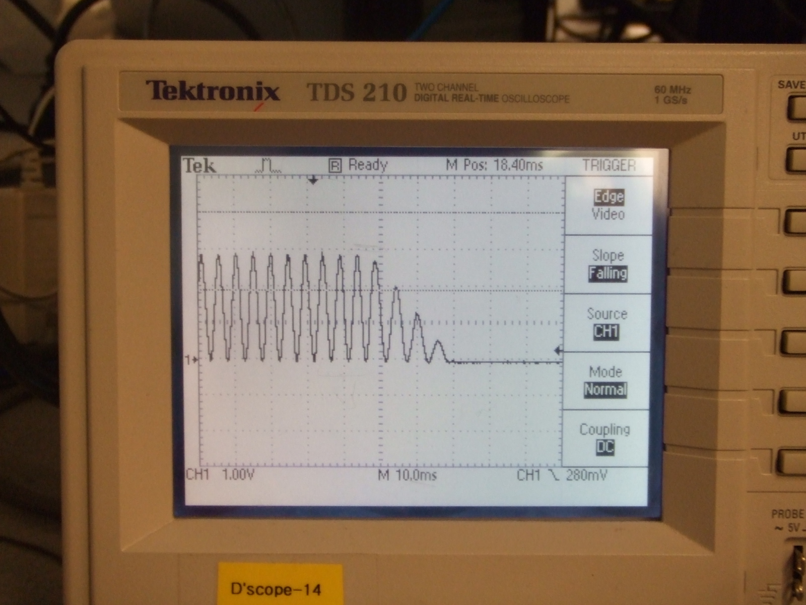
Karplus-Strong algorithm was originally used to produce plucked string sound. Compared to other groups using Karplus-Strong algorithm, we found that the length of the noise affect the sound characteristics. After some testing, generating the same frequency using different length of white noise does actually give different sounds with the same pitch. This might be the reason why the sounds we generated are similar to those of piano. Playing 2 and 3 notes together can be done simply by generating 2 or 3 sounds and taking the average of them (adding them up will have the effect but need to maintain the volume at the same level). The following picture shows the wave form of note C2 (2 octaves below middle C) generated by our synthesizer:
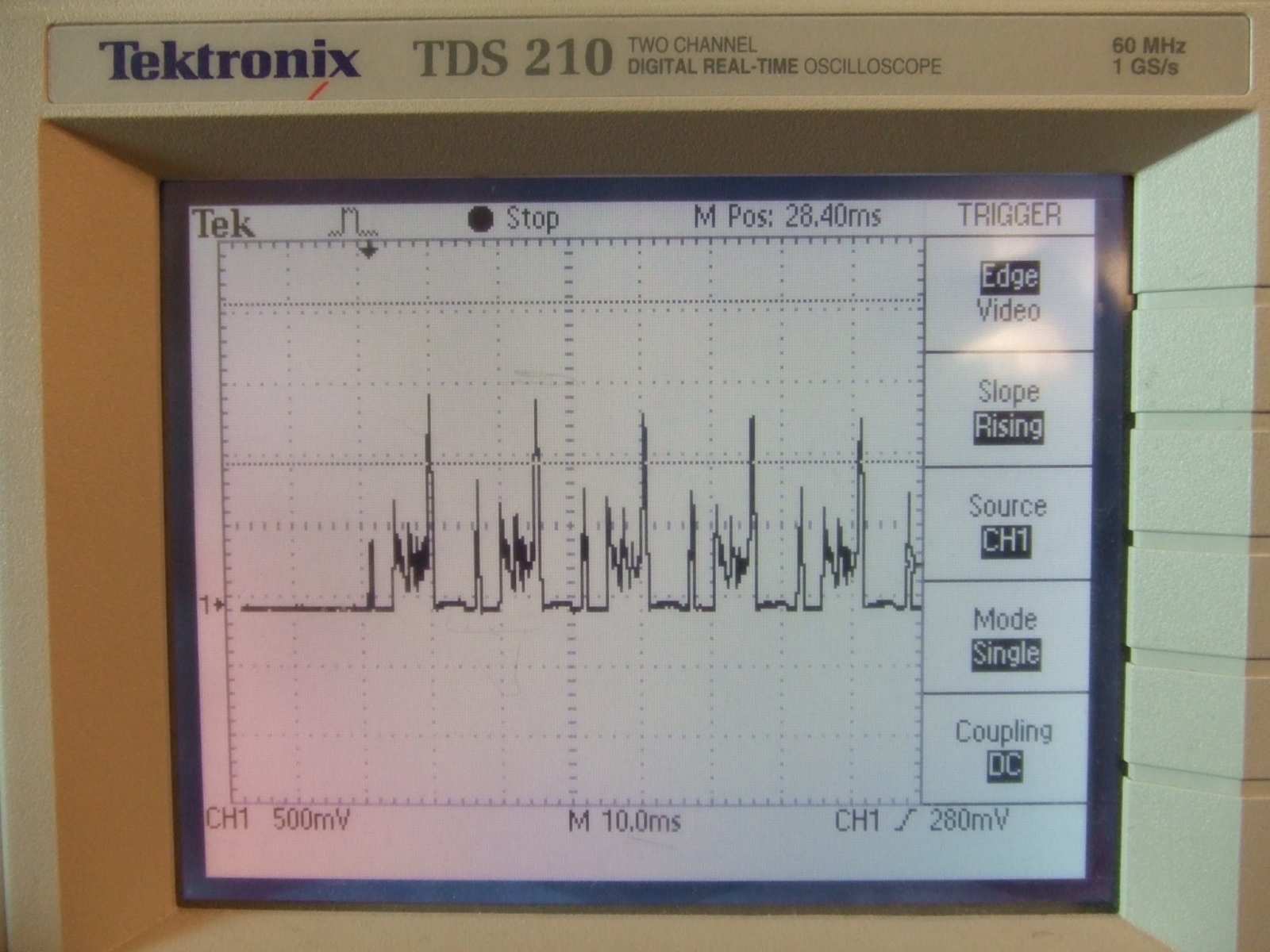
According to the readings on the scope, the period was around 15.3 milliseconds, which stood for 65.359Hz. The frequency of C2 is 65.4 Hz, and the difference resulted from the restriction that the length of noise can only take integer value, and we used a length of 170 with OCR0A = 180 and prescalar = 8 in this case. The sound generated was at 65.35 Hz, which is pretty accurate. Normal human (i.e Vic, Kalina, and people of some other groups) ears can barely distinguish the differences, so we are pretty happy about the result.
Sound decaying speed
One of the modes that we have is to change the decay speed of notes. We were able to play notes at the same frequency with 6 different decay speeds. The following pictures show the fastest decaying and the slowest decaying speed of the same note:
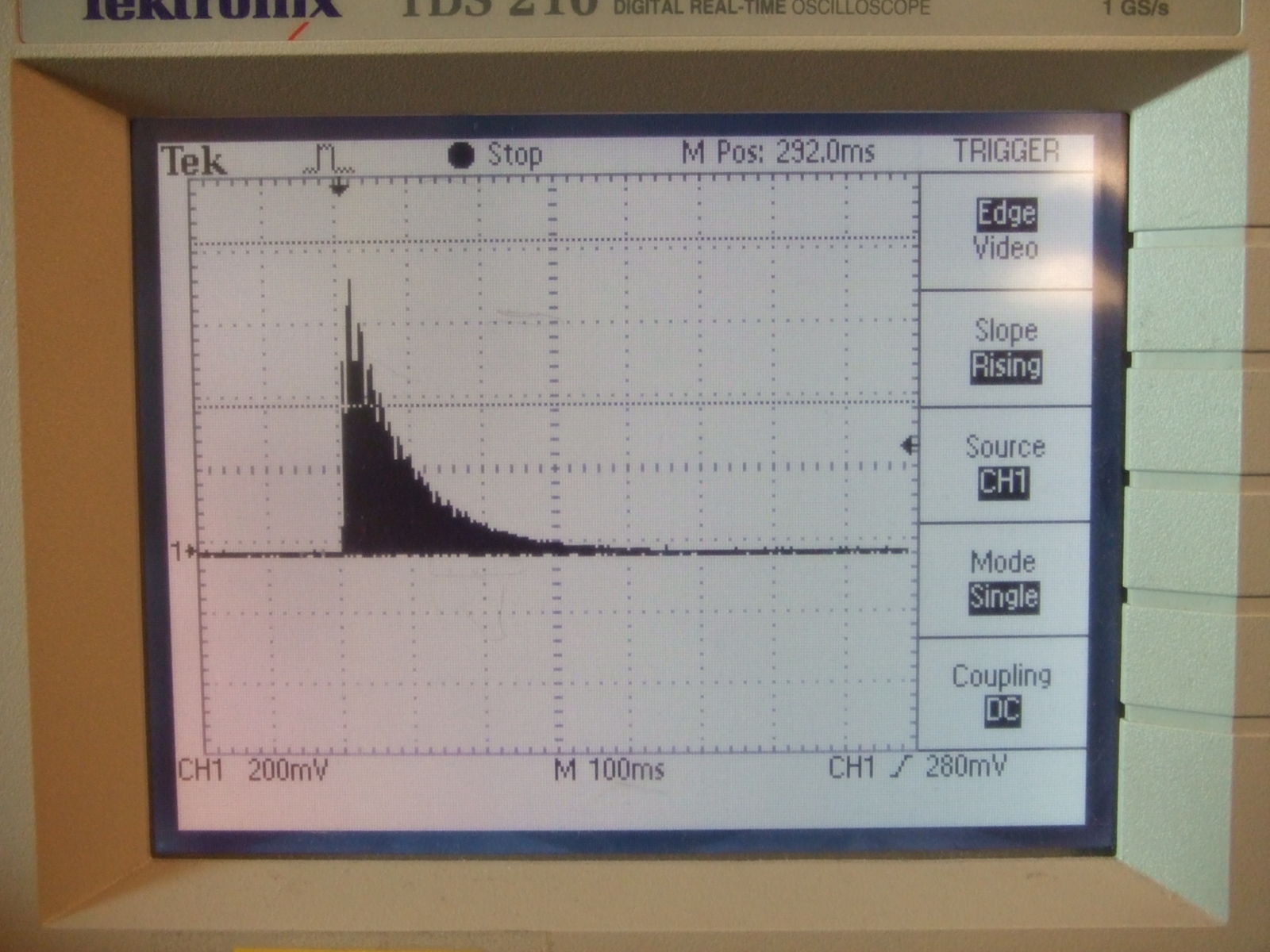
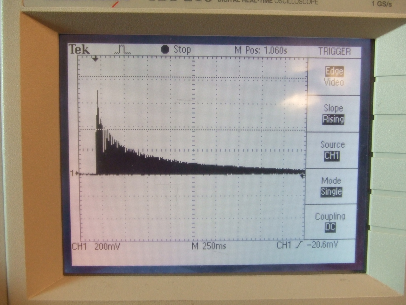
Starting from the same amplitude, the fast decaying one took only 200ms to reach 80mv and the slow one took about 1250ms.
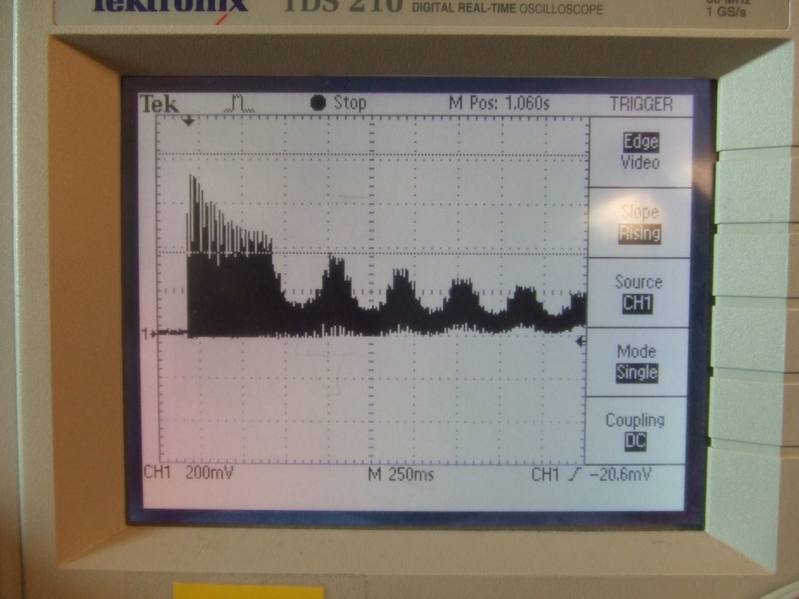
Volume control
The infrared distance sensor was used to change the volume of the sound generated. When the hand got closer to the sensor, the sound would become louder. The following pictures demonstrated the idea:
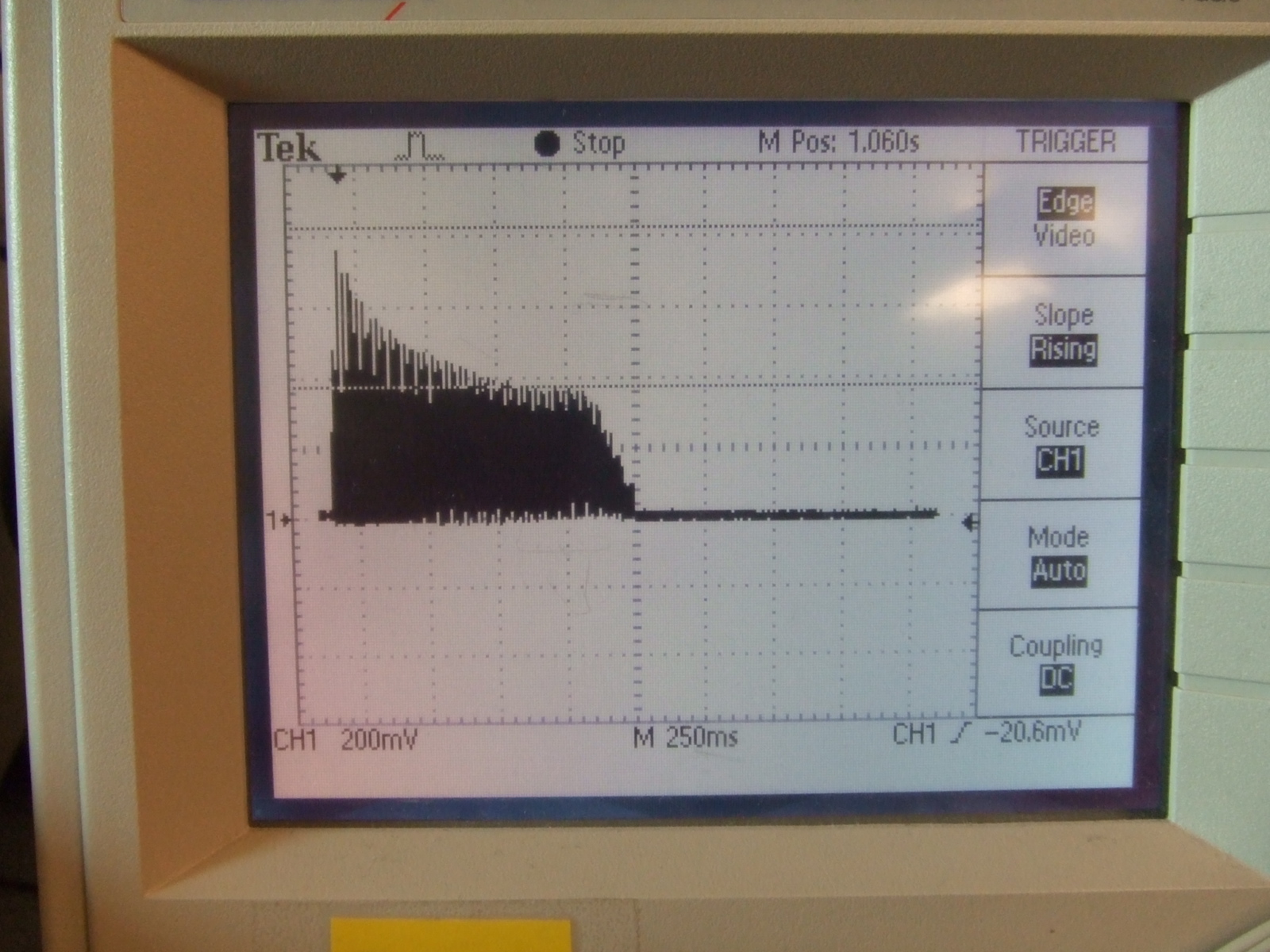
In the first picture, I moved away my hand about 800ms after the start of the sound, so the sound completely died within 250ms.
In the second picture, I moved my hand up and down when the sound was playing. The effect can be seen clearly from the plot.
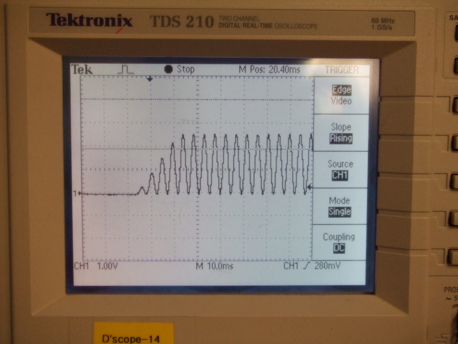
Sine wave generation
The sine wave generation turned out very well. We were able to produce accurate frequency sound, with a ramp up and ramp down at the beginning and end of each wave. Below are images of the ramp up and ramp down functionality of the sine wave mode. We were producing a frequency of about 200 Hz for this mode generation, and it's possible to see that this is in fact the frequency of the sound being generated.
When running our device there are some constraints on the speed at which you can play the touchpad. In the modes that take longer to execute the speed is limited more than in others, such as the chords mode in which three tones are generated simultaneously. If the user tries to play notes too quickly, some of them simply will not be played and the user will have to re-tap the touchpad to generate the sound. This is not a very big issue, as the time between notes is still relatively short and usually, while playing, it does not sound like there is a limiting timeframe.
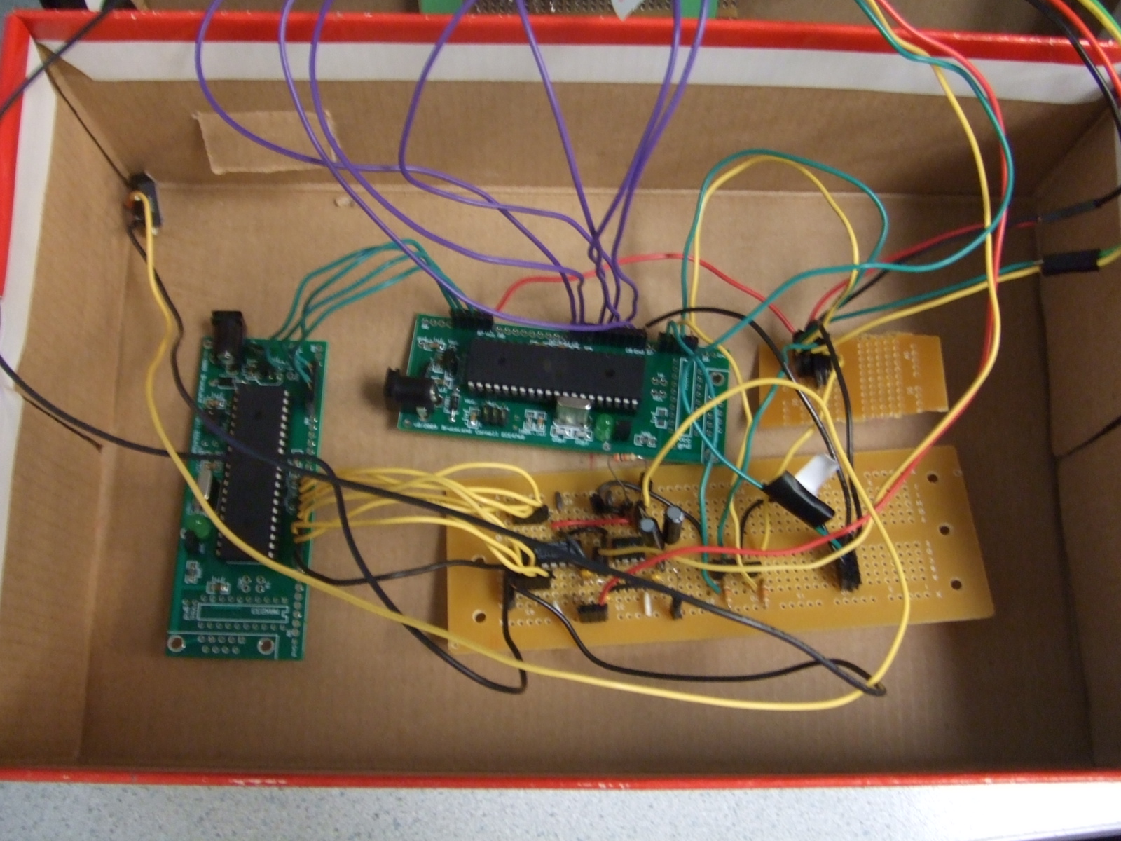
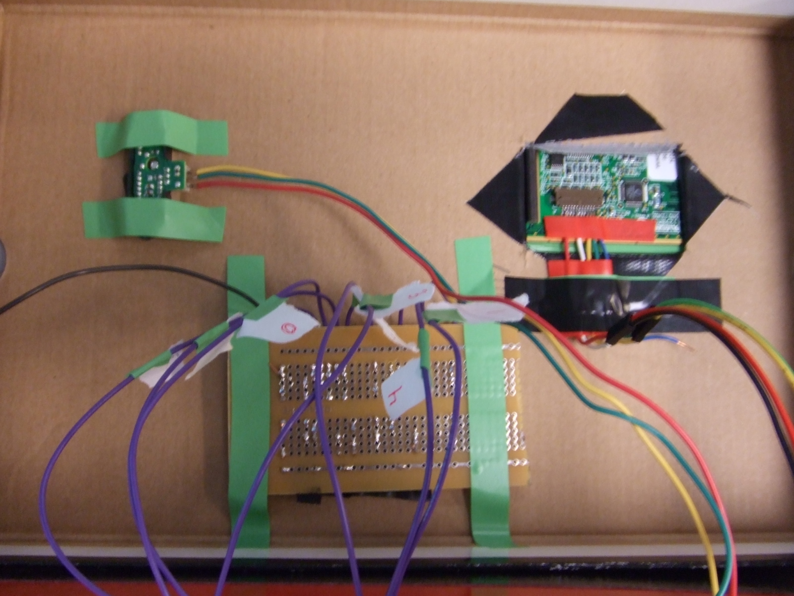
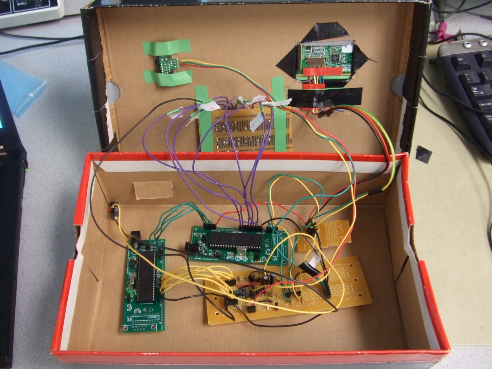
Our design has minimal user interaction; only one finger at a time physically interacts with the device. All of the power supplies and AC power adapters are located in one section of the back of the device, to isolate the possibly problematic power sources from the user. Furthermore, the entire circuit is placed inside a box so that no open circuitry could be potentially touched by the user. We are producing a low voltage sound wave, however, turning up the speaker volume too high could still potentially harm a user or others in the vicinity of the device.
The Touchpad/Infrared Music Synthesizer does not emit signals that will interfere with other projects.
This device can be used by individuals who are capable of blocking the distance sensor in some manner, and interfacing with the touchpad as one would with a laptop computer touchpad. The device has a simple design in order to ensure as much enjoyment out of its use as possible.
Things we tried which did not work
Initially, we wanted to use a very simple DAC for the sound generation through an R2R circuit. To amplify the signal, we were planning on implementing the variable voltage by constructing a voltage-controlled op-amp. To do this, we tried making a voltage-controlled resistor by using a transistor for a variable resistance. Unfortunately, since our voltage ranged from 0 to 3V, we could not use the transistor in the ohmic range, where it exemplifies a variable resistor. We resorted to using the DAC0808 which provided us with an easy implementation of a voltage controlled amplifier.
We had a lot of trouble finding a touchpad that we could interface with. The first touchpad we tried was not a Synaptics device, and without the data sheet we could not extract useful information from it. The second touchpad we tried proved to be missing connector pins, so we had to reject that one as well. Finally, we found an old laptop touchpad in the junk box and used it instead. Furthermore, we initially tried to forego the pull-down transistors for the touchpad data and clock lines; however we found that we were reading incorrect data when we were trying to set pins as inputs and outputs along the same line.
Another problem we ran into with the touchpad was the implementation of mode change. Initially, we planned on using a button to change the mode of the sound generation, however, we found that the ISR was taking over the state machine for the button detection. Thus, we decided to use the touchpad to control the mode. With this design, we would be using the ISR for mode selection and so would no longer have to worry about it blocking other parts of the program. Furthermore, it kept the design simple yet versatile.
Finally, we found that we could not generate as many Karplus-Strong plucked string waves as we had initially wanted to. Each note that we generated needed to index a long array of random numbers, and we found that we didn't have enough data memory to implement playing more than three notes at a time.
Conclusions
Expectations
We were able to successfully implement all of our six modes, and are pleased with the result. Initially, we were planning on using stretch resistors as the interface between the user and sound generation. After deciding on a touchpad, we realized that our design could change usability and functionality in a number of ways. For example, we integrated new modes of play from the touchpad data.
We were hoping to be able to do record, playback, and a beat generation mode initially. If we had more time, we would have liked to look into the implementation of all of these functionalities. The limitations on the data memory for the sound generation MCU may have proved to be an obstacle in tackling these challenges.
The touchpad sensor ended up working out better than we had expected. We initially thought that we would have to do some calculations through the MCU to control the volume of the sound we were producing. Having the volume control completely through hardware simplified our design and reinforced the importance of hardware design in a project that was mainly focused on software design development.
We found that the most difficult and time consuming part of the project was getting communication between the touchpad and between the two MCUs working. We lost invested a lot of time into the first touchpad we had purchased, and then essentially started over with the second one. Had we had more time, one thing we may have done differently is to explore other musical properties that we could manipulate with the DDS sound generation we were using. It would have been helpful had we done more research on music generation before tackling the project. Overall, we were happy with the outcome of our project.
Intellectual Property, Standards and Ethics
Our design conformed to the ISO 16:1975 music note standard. No code was used to generate our programs and no reverse engineering was performed. Furthermore, no non-disclosure agreements were signed. Our device does not contain an RF transmitter so it did not fall under FCC regulations. We did not develop this device to be produced commercially. If it were to be produced commercially, legal considerations need to be considered for product safety.
We adhered to the IEEE code of ethics throughout the design of our project. We made sure that at all times we were not endangering the students, TAs and others around the lab. For the SPI communication, when we were having trouble, we collaborated with other groups who had already achieved SPI communication, thereby fostering a constructive and welcoming work environment. We helped other teams when they were in need of it, and were open to ideas and suggestions from others about our project. We did not lie about our actions or give any form of false data from our device. We do not claim to have thought of a musical synthesizer through a touchpad ourselves, and were inspired by many other instruments throughout the design process, such as the piano and Theremin.
Appendix
Codes
Schematics
2N3904 (Touchpad)
resistors are 10k
Budget
| Part Name | Quantity | Unit Price | Total Price |
| ATMega644 | 2 | Sampled | - |
| Prototype Board | 2 | $4 | $8 |
| Power Supply | 3 | $5 | $15 |
| Solder Board | 2 | $2.5 | $5 |
| Sharp GP2D120XJ00F Infrared Sensor | 1 | $12.18 | $12.18 |
| Synaptics Touchpad (TM41PDD234) | 1 | Junk Box (broken laptop) | - |
| Header Plugs | 65 | $0.05 | $3.25 |
| LED's | 7 | Lab | - |
| Capacitors, Resistors | Several | Lab | - |
| DAC0808(DAC) | 1 | Lab | - |
| LF353(Op-amp) | 1 | Lab | - |
| 2N3904(Transistor) | 2 | Lab | - |
| 2-pin Flat Jumper Cable | 4 | $1 | $4 |
| DIP Socket | 2 | $0.5 | $1 |
| GRAND TOTAL | $48.43 |
Tasks
- Kalina Jordanova:
- Solder boards
- Touchpad interfacing coding
- Volume Controller circuit building
- Construction of final device
- Report
- Wei-jiunn (Vic) Jang:
- Prototype board
- Sound generation coding
- Sound Testing
- Website Building
- Report
Reference
- Vendor Sites
- Digikey
- Background Knowledge
- PS/2 Protocol (computer-engineering.org)
- Karplus-Strong Plucked String Algorithm (from ECE 4760)
- SPI code from ECE 4760 page and TA Ruibing Wang
- Frequencies of musical notes
- Datasheets
- Synaptics Touchpad Interfacing Guide (Google/Synaptics)
- Sharp GP2D120XJ00F Infrared Sensor (Digikey)
- LM353 (National)
- DAC0808 (National)