Flexicopter
Kayla DesPortes, ksd28
Jayashree Kumar, jk483
Zechariah Dzegede, zkd2
Introduction
The purpose of our project is to control a toy helicopter using flex sensors attached to a glove. The flex sensors are intended to replace the remote control that is generally used to fly the helicopter. Additionally we also created another mode which will allow us to use an accelerometer to control the forward and backward, and left and right movements, while using a flex sensor to control the throttle of the helicopter. We have two gloves each with three flex sensors attached to it. One of the gloves has an accelerometer attached to it.
High Level Design
1. Rationale
One of our group members Zack ordered a helicopter from eBay for his own personal use. Once we started playing with it, we thought it would be a cool idea to try to control the helicopter without the controller and fly it using one's own body movements. Our initial idea was to attach electrodes to our arm to detect the flexing of the muscles on the forearm. Using the signals from the electrodes we thought that we would be able to send these signals to the helicopter and control it. However, Professor Land informed us that it might be dangerous to conncet electrodes to our arm and additionally the signals received from the electrodes might too small to feasibly use. Instead we decided an alternative would be to attach flex sensors to the hand and by bending our fingers we would be able to control the movements of the helicopter. This was how the Flexicopter was born!
2. Background Information
Flex Sensors
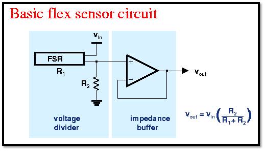
Flex sensors are basically variable resistors. As seen from the Figure 1 below, we will use a voltage divider circuit we to obtain the voltage across the flex sensor. As you bend the flex sensor, its resistance gets higher and hence the voltage across it gets higher. We will use the changing voltage to control the helicopter.
Figure 1: Flex Sensor Circuit
Accelerometer
An accelerometer measures how much you accelerate the device relative to the acceleration of free fall which is gravitational acceleration, g. Based on the relative acceleration of the device, it outputs a voltage. So as you move the accelerometer left, right, back and forward, the voltage changes. Similar to the flex sensors, we will use the varying voltage to control the helicopter.
Figure 2: Accelerometer
Helicopter
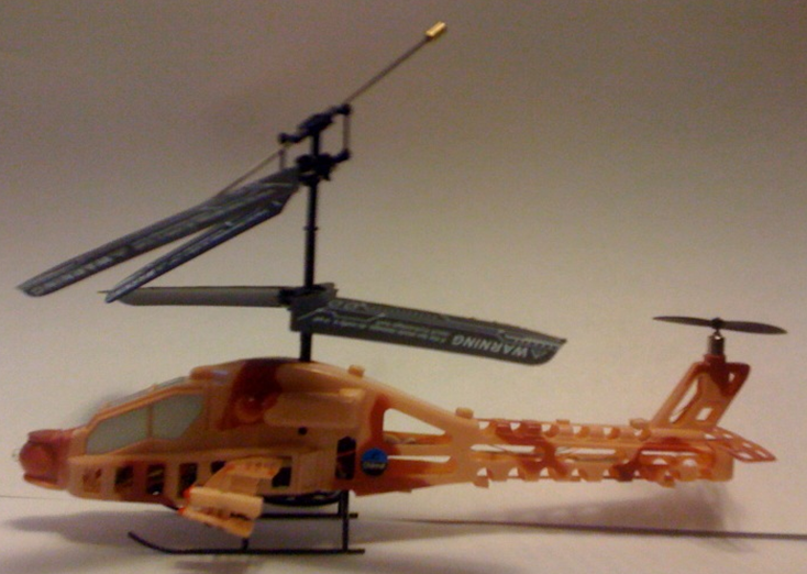
The way the helicopter works is that the Light Emitting Diode (LED) transmits bit streams repeatedly from the controller to the helicopter through RF waves. The receiver on the helicopter obtains these bit streams and moves the helicopter. Our setup mimicked this.
Figure 3: Helicopter
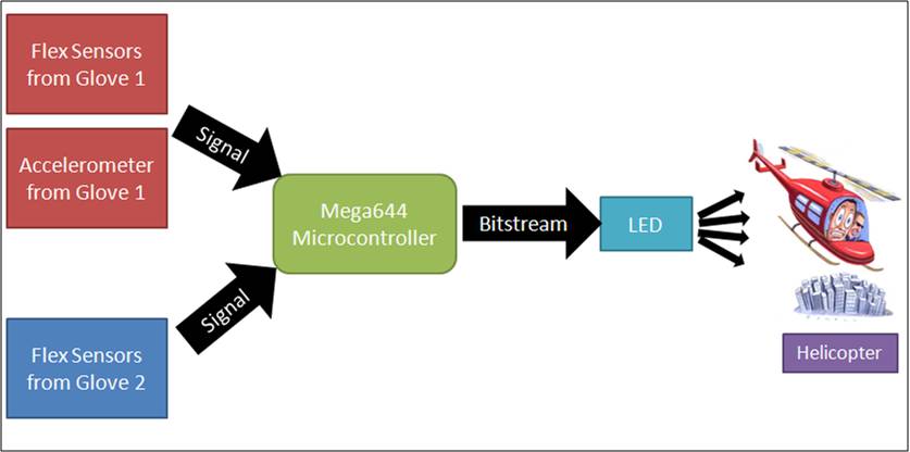
3. Logical Structure
Figure 4: Overall structure of our design
4. Hardware/Software TradeOffs
Our budget restricted the quality of helicopter we were able to use. We used a low quality fifteen dollar helicopter ordered from Hong Kong. This meant that we had no information about what kind of bit stream pattern the controller of the helicopter was using and we had to figure it out ourselves. Additionally, the low quality meant that the helicopter could easily be damaged. Our worst fears came true when our helicopter's stabilizer broke off two days before the final project was to be demoed because we had crashed it often when testing it. For the original helicopter, the bit stream pattern was too complicated for us to figure out any patterns they were following when we moved the helicopter backwards, forwards, left and right because there was some kind of error correction occurring and we could not figure out the algorithm. Hence we had to limit the motion of the helicopter to ten levels of throttle, and for each level of throttle we limited the helicopter to five levels of right,left, forward, backward, forward-right, forward-left, backward-right and backward-left. This still meant that we had to record 400 different bit streams, which included taking 400 pictures on the oscilloscope and translating them into a pattern that our code could translate send out. However, for the helicopter we ended up using after the original one broke, the bit stream patterns were much simpler and we were able to observe obvious patterns.
Software and Hardware Design
1. Hardware Design
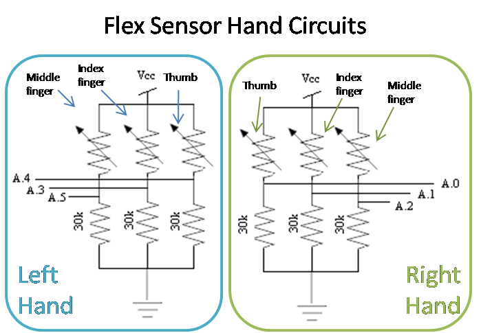
As mentioned in our introduction, we allow the helicopter to be controlled in two modes. The first mode is the flex sensor mode, where only the flex sensors control the movement. In this mode, on the right hand, the flex sensor on the thumb controls the throttle, the flex sensor on the index finger controls the 'left' movement, the flex sensor on the middle finger controls the 'right' movement. On the left hand, the flex sensor on the index finger controls 'forward' motion while the flex sensor on the middle finger controls the 'backward' motion. The second mode is the accelerator mode, where the accelerator combined with on flex sensor controls the movement of the helicopter. Tilting the accelerator on the right hand up, down, to the left and to the right moves the helicopter forward, backward, left and right respectively. The flex sensor on the thumb of the left hand controls the throttle of the helicopter. These are summarized in Figure 5 shown below.
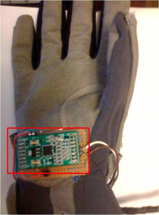
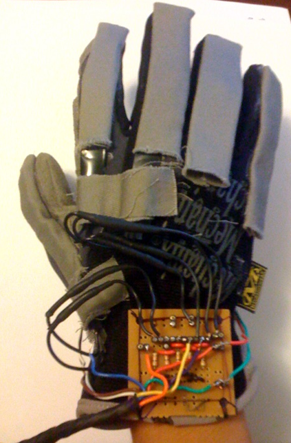
You can see the following components of the glove from Figure 6 below. We sewed rectangular pockets of cloth on each individual finger of the glove in order to insert the flex sensors. A voltage divider circuit was built on a protoboard, which was then sewn on to the lower portion of the glove. Output wires from the protoboard are then connected to the microcontroller as inputs.
Figure 6: The Right Glove
The voltage divider circuit constructed on the protoboard is shown below in Figure 7.
Figure7: Flex Sensor Circuits on the hands
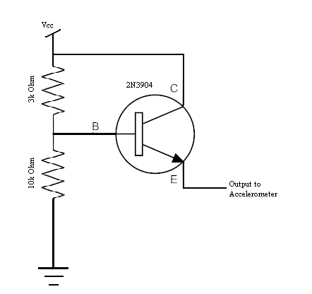
The accelerometer and its associated circuit was placed on another protoboard and this was sewn onto the back of glove, on the palm of the hand as shown in Figure 2. We had to add additional circuitry to the accelerometer because the maximum voltage it could take was 3.6V and the VCC that we were sending to it from the microcontroller was 5V. Hence we needed a circuit that would step down the voltage from 5V to about 3V. We knew that the transistor posed a certain amount of impedence and we also knew that we had to have a voltage less than 3.6V at the emitter of the transistor which was then connected to the VCC input of the accelerometer. Instead of using theoretical equations to determine the resistances on the voltage divider circuit, we used trial and error and determined that we needed 10 kiloOhms and 3 kiloOhms resistors. As shown below in Figure 8, the voltage at the base of the transistor will be about 3.84V. This gives us approximately 3.1V at the emitter of the transistor and this gets sent to the VCC of the accelerometer.
Figure 8: AccelerometerCircuit
Since we did not want to make use of the STK500 board, we used a prototype board for the Mega644 and attached the Mega644 chip on it. We soldered all the diffferent components necessary onto the prototype board and then sewed it onto a piece of cloth which we then fashioned to wrap around our arm as shown in Figure 9. This way all the hardware necessary is on our body and nothing is detached.
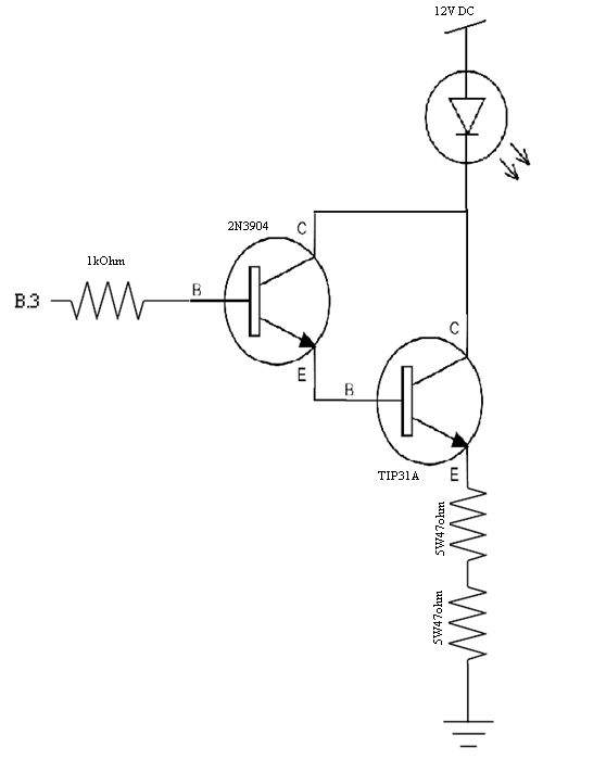
We also have the circuit which takes the bit stream pattern that has been indicated by the code based on which flex sensors we have bent and how much they have been bent, and sends it to the LED. Since we need the signal to be sent to the helicopter to be strong, we have to amplify the current going through the LED. The port pins limit the amount of current drawn to about 30 Milliamperes. We need at least 150 Milliamperes to be sent through the LED in order for the signal to be strong enough. The circuit we constructed is shown below in Figure 10. The basic idea of this circuit is that the current will be drawn from the 12 V voltage source that is connected to the LED.
Figure 9: LED Circuit
2. Software design
The code is set up to operate in two modes: one which is controlled solely by the flex sensors and one which is controlled by the accelerometer and one flex sensor for throttle. To choose between the two modes a digital input is read off of PORTC0, if the input is high the code operates in the accelerometer mode, when the input is low to this port the code operates in the flex sensor mode. The code breaks down into two main sections for both modes: a section which chooses what signal to be sent, and a section that actually creates and sends the signal. The signal to the helicopter consisted of high portions and low portions, of which, the high portions oscillate at a 37kHz rate. After checking several bit streams, it became apparent that the signal was separated into six segments: start bits, 8-bits representing throttle, 4-bits representing right/left motion, 4-bits representing forward/backward motion, 2-bits representing channel a,b, or c, and the last three bits representing trim. The start bits were a high signal, lasting 3280us and a low signal lasting 2120us. These bits were consistent over all ranges of motion. The next 8-bits in the signal were determined to be throttle. The throttle increased linearly from 0x00 to 0xC9 based on how much the throttle was increased. The four bits following that determined right and left motion. If the controller was signalling maximum right, the bits would be 0x0 and if it was maximum left the bits would be 0xF. The forward and back, which are the next four bits, work in a similar manner; when the controller was signaling maximum forward the bits were 0x0 and when it was maximum backward the signal was 0xF. The two bits following that signify which channel the helicopter is operating on. If the pattern was 0b00 then it meant channel a, 0b01 was channel b, and 0b10 was channel c. Of the three trim bits the third to last bit was always a 0 and the second to last turned to one when left trim was pressed, and the last bit turned to one when the right trim was pressed. To compile the signal from the inputs of the flex sensors and accelerometer, the flex sensors and accelerometer were tested and the maximum and minimum voltages were set in the code. We set a linear relationship between the voltage coming in and the intensity of the throttle, right-left, and forward-back motion. The flexData() and accellData() functions were called on according to the mode select, and these functions acquired the analog data from all the input ports which applied. The input data was then used in the functions accelSignal() and flexSignal(), which actually compiled the signal to be sent in an array. These functions were called on 100 times a second giving the system a signal to output.
The function signalSender() combined with a compare match ISR on timer 0 were used to send the signal to the helicopter. The ISR triggered at 74kHz, which is twice as fast as the 37kHz we were sending out. so we could set it up to toggle on match. The signalSender() function goes through the 41 bit signal composed by accelSignal() or flexSignal(), sending the 37kHz signal when a high value was being sent and a zero when a low value was being sent. When the full signal has finished sending it sends a low value for 10000 ticks to mimic the signal sent from the controller of the helicopter. Only when this has completed does it start over, sending a new signal.
3. Things tried that did not work out
The main problem that we had was that we broke our first helicopter. This helicopter had a very complicated bit stream that had some sort of error correction code that was too difficult to figure out because we could not even tell what was representative of one's and zero's in the code. Because of this issue we took 400 screen shots on the oscilloscope and then translated them into a bit stream that we compiled and sent out in our code. The 400 hundred values consisted of doing 11 throttle values (no throttle to maximum throttle) and then within each of these ten throttles (zero throttle was the same for everything because it was off) we had 10 values going from forward to back, 10 values from right to left, 10 values from forward-left to back-right, and 10 values from forward-right to back-left. Because we were already at 400 we were not able to go into changing the trim, which is an offset for the helicopter for spinning right or left. The code was set up to choose out of a matrix the values based on the inputs from the flex sensors and the accelerometer. We had this design set up and working with the flex sensors and accelerometer, however the helicopter was offset with a spin and we could not correct this with our set up due to the lack of trim settings. This spinning made it almost uncontrollable in the forward-back and left-right directions, although the throttle was easily controllable. We did check the signal we were sending out on the oscilloscope against the pictures we had taken, and we were sending the correct signals out for the hand motions we were making. Unfortunately, two days before we checked off our project the helicopter we were using crashed and the stabilizer broke off, completely inhibiting any control. Luckily we were able to get another helicopter and decode its bit stream, which was significantly more simple than the previous helicopter's.
Results of Design
We compared the performance of flying our helicopter with the flex sensors and accelerometer with how the helicopter flies when we control it using the remote controller. It works almost exactly the same way. Our flex sensors are able to attain the maximum throttle speed as the controller does. While flexing our thumb does not provide as much range in the different levels of throttle as the controller does, we are still able to raise the helicopter up and down easily. When we use the controller to move the helicopter left or right, it mostly spins in the left-direction or right-direction and slowly moves to the left and right respectively. Our flex sensors display the same functionality. The flex sensors are able to move the helicopter forward and backwards visibly. When comparing the functionality of the accelerometer and the flex sensors, the flex sensors are able to control the helicopter better than the accelerometer. However, we feel that using the accelerometer is more intuitive than using the flex sensors, since tilting the accelerometer left and right moves the helicopter left and right, and tilting it up and down moves the helicopter forward and backward. The biggest difference between controlling the helicopter using the flex sensors and controlling it using the remote control would have to be distance that we are able to control the helicopter. We can only control the helicopter within a limited distance from the LED with our circuit. A more distinct disadvantage using our circuit is that we can only start the helicopter if the LED can be seen visibly from the helicopter. This means for example we cannot have the starting position of the helicopter to be from the floor unless the LED is on the floor as well. We assumed that this was probably due to some additional changes in the bit stream patterns that we were not able to detect using the oscilloscope.
Here is a video one of the team members Zack flying the helicopter using the flex sensors:
Conclusions
1. Expectations vs. Actual Results
We did not meet our expectations that were previously set out at the beginning of this project. We had assumed that we would be able to decode the bit stream quickly, however, with our first helicopter this was not the case. We spent hours acquiring the different bit streams, only to have them prove useless when we broke the helicopter. Our code ended up becoming a lot less complicated when the new helicopter was included in the project. We were able to still utilize both an accelerometer mode and a flex sensor mode, and allow the user to choose between them by setting PORTC0 to zero (for flex sensor mode) and one (for accelerometer mode). It was more difficult to control than originally anticipated because it takes a lot of concentration to keep the motions of your fingers separate.
One of the biggest problems we encountered was because of the flex sensors. When we initially used them in our circuit, based on their resistances, they gave us a voltage range of ~0-3V. However, over the course of the project, mostly at very unexpected times, flex sensors would lose their ability to change over the same range. Our voltage ranges usually changed to ~0.4-0.6V making them practically unusable for our application. One of the flex sensors ended up randomly working, but apart from that it was a very cumbersome problem. Since we decided to only use six flex sensors it turned out fine in the end, since we ended up having about three flex sensors that no longer worked properly. Our code was set up to allow for quick changes in calibration values depending on what flex sensor we are using. We developed some code that was able to calibrate the flex sensors however we had to rewrite a lot of our code to make up for the fact that towards the last 3 days of our project several unfortunate events happened causing us to have to redo several aspects of the hardware and code. We ended up leaving the calibration to be a pre-compile set up.
2. Usability
We feel that our flexicopter can be used by most people with good hand coordination. It takes a while to get used to controlling the helicopter using the flex sensors and accelerometer. It is a steep learning curve, but we feel that once that curve has been overcome, users will thoroughly enjoy the feeling of controlling a helicopter using their own hands!
3. Appendix
Code
#include <avr/pgmspace.h>
#include <stdio.h>
#include <stdlib.h>
#include <string.h>
#include <stdint.h>
#include <inttypes.h>
#include <avr/io.h>
#include <avr/interrupt.h>
#include <math.h>
#include <util/delay.h>
#include <avr/sleep.h>
//I like these...me too
#define begin {
#define end }
//The various sensors
unsigned char sensor1,sensor2,sensor3,sensor4,sensor5,sensor6,sensor7,sensor8;
//The pointers to the sensors
char *throttleP, *forwardP, *backP, *leftP, *rightP, *throttleAccelP, *rightleftP, *forwardbackP; //P for pointer
//Increment for which sensor to pick
char sensorCounter;
volatile unsigned int count;
unsigned int signalPointer; //pointer to count through one signal
char bitType;
char bitSent, turnSel;
//volatile unsigned int inputCount; //count for signalSender to be called
//accelerometer declarations
#define accelSampTime 768
volatile unsigned int accelCount;
//Declaration of variables for flex sensors high and low values
unsigned int throttleHighAccel, throttleLowAccel; //Throttle accelerometer high/low
unsigned int throttleHighFlex, throttleLowFlex; //Throttle flexsensor high/low
unsigned int leftHigh, leftLow; //Left high/low
unsigned int rightHigh, rightLow; //Right high/low
unsigned int forwardHigh, forwardLow; //Forward high/low
unsigned int backwardHigh, backwardLow; //Back high/low
unsigned int leftHighAccel, leftLowAccel; //Left high/low for accelerometer
unsigned int rightHighAccel, rightLowAccel; //Right high/low for accelerometer
unsigned int forwardHighAccel, forwardLowAccel; //Forward high/low for accelerometer
unsigned int backwardHighAccel, backwardLowAccel; //Back high/low for accelerometer
//Bits within the bit stream decode
#define sm0 3 //Small 0 bit
#define sm1 0 //Small 1 bit
#define bg1 1 //Big 1 bit
#define bit1 5 //first 1 bit
#define bit2 6 //second bit 0 bit
//Bit lengths in half periods of 37.0kHz
#define sm0len 37 //~520us
#define sm1len 61 //~860us
#define bg1len 123 //~1720us
#define OneBit 234 //~3280us for first bit 1
#define TwoBit 151 //~2120us for second bit 0
//Define Time between sampling flex sensors
//#define flexSampTime 3840 //allows for the data to be read 20times/sec using timer0
//#define flexSampTime 1536 //allows for the data to be read 50times/sec using timer0
#define flexSampTime 768 //allows for the data to be read 100times/sec using timer0
//Time count down to trigger reading the values from the flex sensors 20times/sec
volatile unsigned int flexCount;
char allBits[41] = {5,6,0,3,0,3,0,3,0,3,0,3,0,3,0,3,0,3,1,3,0,3,0,3,0,3,1,3,0,3,0,3,0,3,1,3,0,3,0,3,0};
//***********************************************************
//Singnal Sender sends the signal to the IR emitter
void signalSender(void)
begin
//When the signalPointer is not 20 then we are transmitting a bit stream
if (signalPointer < 41)
begin
//If you finished sending the last bit you can move on
if (bitSent)
begin
bitType = allBits[signalPointer];
bitSent = 0; //Mark the bit as unsent
if ((bitType == sm0) || (bitType == bit2)) //if its zero or
begin
TCCR0A = 0b00000010; // turn off OC0A and clear-on-match because sending a low value
PORTB = 0x00;
end
else
begin
TCCR0A = 0b01000010; // turn on toggle and clear-on-match because sending a high value
end
end
//check if bit has completed
else if (((bitType == sm0) && (count == sm0len)) ||
((bitType == sm1) && (count == sm1len)) ||
((bitType == bg1) && (count == bg1len)) ||
((bitType == bit1) && (count == OneBit)) ||
((bitType == bit2) && (count == TwoBit)))
begin
count = 0; //reset count
bitSent = 1; //update bitSent to true
signalPointer++;
end // if bit complete
end // if signalPointer less than 41
else //if signalPointer 41
begin
if (count >= 10000)//8646)
begin
signalPointer = 0;
count = 0;
TCCR0A = 0b01000010; // turn on toggle and clear-on-match because we have held the signal low for 10000
end
else
begin
TCCR0A = 0b00000010; // turn off OC0A and clear-on-match because sending low signal for 10000
PORTB = 0x00; //turn off output between signals
end
end
end
//***********************************************************
//timer 0 comare match ISR for the signalSender
ISR (TIMER0_COMPA_vect)
begin
//Count how many half periods the 37kHz signal has gone through
count++;
signalSender();
flexCount--; //Decrement flexCount each time
accelCount--;
end
//***********************************************************
//***********************************************************
void flexSignal()
begin
///////////////////
////THROTTLE///////
///////////////////
double throttlTemp1,throttleTemp2;
int integerThrottle;
integerThrottle = ((201/(throttleHighFlex - throttleLowFlex)) * (*throttleP)) + (201 - ((201/(throttleHighFlex - throttleLowFlex))*throttleHighFlex));
if (*throttleP < throttleLowFlex)
begin
allBits[2] = 0;
allBits[4] = 0;
allBits[6] = 0;
allBits[8] = 0;
allBits[10] = 0;
allBits[12] = 0;
allBits[14] = 0;
allBits[16] = 0;
end
else
begin
allBits[2] = (integerThrottle & 0b10000000) >> 7;
allBits[4] = (integerThrottle & 0b01000000) >> 6;
allBits[6] = (integerThrottle & 0b00100000) >> 5;
allBits[8] = (integerThrottle & 0b00010000) >> 4;
allBits[10] = (integerThrottle & 0b00001000) >> 3;
allBits[12] = (integerThrottle & 0b00000100) >> 2;
allBits[14] = (integerThrottle & 0b00000010) >> 1;
allBits[16] = (integerThrottle & 0b00000001);
end
//////////////////
////LFT-RT////////
//////////////////
char offRightLeft;
int integerRightLeft;
int integerLeft = (((200/(leftHigh - leftLow)) * (*leftP)) >> 5) + 8;
int integerRight = ((200/(rightHigh - rightLow)) * (*rightP)) >> 5 ;
//Choosing which result to use for right-left motion
if ((integerLeft - 8) > integerRight)
begin
integerRightLeft = integerLeft;
offRightLeft = (*leftP < leftLow);
// PORTD = PORTD ^ 0x02;
end
else
begin
integerRightLeft = integerRight;
offRightLeft = (*rightP < rightLow);
// PORTD = PORTD ^ 0x04;
end
if (offRightLeft)
begin
allBits[18] = 1;
allBits[20] = 0;
allBits[22] = 0;
allBits[24] = 0;
// PORTD = PORTD ^ 0x01;
end
else
begin
allBits[18] = (integerRightLeft & 0b1000) >> 3;
allBits[20] = (integerRightLeft & 0b0100) >> 2;
allBits[22] = (integerRightLeft & 0b0010) >> 1;
allBits[24] = (integerRightLeft & 0b0001);
end
////////////////////
////FWD-BACK////////
////////////////////
int result3, result4;
char offForwardBack;
int integerForwardBack;
int integerForward = (((200/(forwardHigh - forwardLow)) * (*forwardP)) >> 5) + 8;
int integerBack = ((200/(backwardHigh - backwardLow)) * (*backP)) >> 5 ;
//Choosing which result to use for right-left motion
if ((integerForward - 8) > integerBack)
begin
integerForwardBack = integerForward;
offForwardBack = (*forwardP < forwardLow);
// PORTD = PORTD ^ 0x02;
end
else
begin
integerForwardBack = integerBack;
offForwardBack = (*backP < backwardLow);
// PORTD = PORTD ^ 0x04;
end
if (offForwardBack)
begin
allBits[26] = 1;
allBits[28] = 0;
allBits[30] = 0;
allBits[32] = 0;
// PORTD = PORTD ^ 0x01;
end
else
begin
allBits[26] = (integerForwardBack & 0b1000) >> 3;
allBits[28] = (integerForwardBack & 0b0100) >> 2;
allBits[30] = (integerForwardBack & 0b0010) >> 1;
allBits[32] = (integerForwardBack & 0b0001);
end
end
//***********************************************************
//***********************************************************
//Task for getting ADC data from flex sensors
void flexData(void)
begin
flexCount = flexSampTime;
//Grab analog data off flex sensors PORTA0-4
if (sensorCounter == 0x00)
begin
sensor1 = ADCH;
ADMUX = (1 << REFS1) | (1 << REFS0) | (1<<ADLAR) + 0b00001;
ADCSRA |= (1<<ADSC);
sensorCounter = 0x01;
end
else if (sensorCounter == 0x01)
begin
sensor2 = ADCH;
ADMUX = (1 << REFS1) | (1 << REFS0) | (1<<ADLAR) + 0b00010;
ADCSRA |= (1<<ADSC);
sensorCounter = 0x02;
end
else if (sensorCounter == 0x02)
begin
sensor3 = ADCH;
ADMUX = (1 << REFS1) | (1 << REFS0) | (1<<ADLAR) + 0b00011;
ADCSRA |= (1<<ADSC);
sensorCounter = 0x03;
end
else if (sensorCounter == 0x03)
begin
sensor4 = ADCH;
ADMUX = (1 << REFS1) | (1 << REFS0) | (1<<ADLAR) + 0b00100;
ADCSRA |= (1<<ADSC);
sensorCounter = 0x04;
end
else
begin
sensor5 = ADCH;
ADMUX = (1 << REFS1) | (1 << REFS0) | (1<<ADLAR) + 0b00000;
ADCSRA |= (1<<ADSC);
sensorCounter = 0x00;
end
//When we have read from all the flexsensors update signal being sent
if (sensorCounter == 0x00)
begin
flexSignal();
end
end
//***********************************************************
//***********************************************************
void accelSignal(void)
begin
allBits[38] = (PINC & 0x02) >> 1; //trim left
allBits[40] = (PINC & 0x04) >> 2; //trim right
PORTD = allBits[40];
////////////////////
////THROTTLE////////
////////////////////
int integerThrottle;
integerThrottle = ((201/(throttleHighAccel - throttleLowAccel)) * (*throttleAccelP)) + (201 - ((201/(throttleHighAccel - throttleLowAccel))*throttleHighAccel)) +24;
//PORTD = ~(integerThrottle);
if (*throttleAccelP < throttleLowAccel)
begin
//PORTD = (PORTD ^ 0x01);
allBits[2] = 0;
allBits[4] = 0;
allBits[6] = 0;
allBits[8] = 0;
allBits[10] = 0;
allBits[12] = 0;
allBits[14] = 0;
allBits[16] = 0;
end
else
begin
//PORTD = (PORTD ^ 0x02);
allBits[2] = (integerThrottle & 0b10000000) >> 7;
allBits[4] = (integerThrottle & 0b01000000) >> 6;
allBits[6] = (integerThrottle & 0b00100000) >> 5;
allBits[8] = (integerThrottle & 0b00010000) >> 4;
allBits[10] = (integerThrottle & 0b00001000) >> 3;
allBits[12] = (integerThrottle & 0b00000100) >> 2;
allBits[14] = (integerThrottle & 0b00000010) >> 1;
allBits[16] = (integerThrottle & 0b00000001);
end
////////////////////
////LEFT-RIGHT////////
////////////////////
int integerLeftAccel;
int integerRightAccel;
integerLeftAccel = (((200/(rightLowAccel - rightHighAccel)) * (*rightleftP)) >> 5) - 2 ;
//PORTD = ~(integerLeftAccel);
allBits[18] = (integerLeftAccel & 0b1000) >> 3;
allBits[20] = (integerLeftAccel & 0b0100) >> 2;
allBits[22] = (integerLeftAccel & 0b0010) >> 1;
allBits[24] = (integerLeftAccel & 0b0001);
////////////////////
////FORWARD-BACK////////
////////////////////
int integerForwardAccel;
int integerBackAccel;
integerBackAccel =~( (((200/(backwardLowAccel - backwardHighAccel)) * (*forwardbackP)) >> 5) - 3 );
//PORTD = ~(integerBackAccel);
allBits[26] = (integerBackAccel & 0b1000) >> 3;
allBits[28] = (integerBackAccel & 0b0100) >> 2;
allBits[30] = (integerBackAccel & 0b0010) >> 1;
allBits[32] = (integerBackAccel & 0b0001);
end
//***********************************************************
//***********************************************************
//Task for getting ADC data from accelerometer and flex sensor
void accelData(void)
begin
accelCount = accelSampTime;
if (sensorCounter == 0x00)
begin
sensor6 = ADCH;
ADMUX = (1 << REFS1) | (1 << REFS0) | (1<<ADLAR) + 0b00110;
ADCSRA |= (1<<ADSC);
sensorCounter = 0x01;
end
else if (sensorCounter == 0x01)
begin
sensor7 = ADCH;
ADMUX = (1 << REFS1) | (1 << REFS0) | (1<<ADLAR) + 0b00111;
ADCSRA |= (1<<ADSC);
sensorCounter = 0x02;
end
else if (sensorCounter == 0x02)
begin
sensor8 = ADCH;
ADMUX = (1 << REFS1) | (1 << REFS0) | (1<<ADLAR) + 0b00101;
ADCSRA |= (1<<ADSC);
sensorCounter = 0x00;
end
//When we have read from accelerometer and throttle flexsensor update signal being sent
if (sensorCounter == 0x00)
begin
accelSignal();
end
end
//***********************************************************
//***********************************************************
//Main loop
int main(void)
begin
/******************************************************************************************************/
/********************************* MCU INITIALIZATIONS BEGIN*******************************************/
/******************************************************************************************************/
//Port B.3 gives the output to the IR emitter
DDRB = 0x08;
PORTB = 0x08;
//Port C.0 for switch mode select
DDRC = 0x00;
PORTC = 0xff;
//LED D.0-D.7
DDRD = 0xff;
PORTD = 0xff;
//Turn on Timer 0 to control the signal to the IR emitter
TIMSK0 = 2; //turn on timer 0 cmp match ISR
TCCR0A = 0b01000010; // turn on toggle and clear-on-match
TCCR0B = 0b00000001; // no clock prescalar and turn on counter
OCR0A = 216; //set the compare reg to 216 time ticks for 37.0kHz square wave pulse
//********ADC*************
//init the A to D converter
//channel zero/ left adj /EXTERNAL Aref
//!!!CONNECT Aref jumper!!!!
ADMUX = (1 << REFS1) | (1 << REFS0) | (1<<ADLAR) + 0b00000;
//enable ADC and set prescaler to 1/128*16MHz=125,000
//and clear interupt enable
//and start a conversion
ADCSRA = (1<<ADEN) | ((1<<ADSC) + 7) ;
/*********************************** MCU INITIALIZATIONS END*******************************************/
/******************************************************************************************************/
/******************************************************************************************************/
/**************************** VARIABLE INITIALIZATIONS BEGIN*******************************************/
/******************************************************************************************************/
//Initialize values
bitSent = 1;
signalPointer = 0;
count = 0;
flexCount = flexSampTime;
accelCount = accelSampTime;
sensorCounter = 0x00;
//Sensor definitions
throttleP = &sensor1;
leftP = &sensor2;
rightP = &sensor3;
forwardP = &sensor4;
backP = &sensor5;
throttleAccelP = &sensor6;
rightleftP = &sensor7;
forwardbackP = &sensor8;
//range for throttle, left-right and forward backward for flex sensors
throttleLowFlex = 15;
throttleHighFlex = 90;
leftHigh = 180;
leftLow = 70;
rightHigh = 255;
rightLow = 15;
forwardHigh = 200;
forwardLow = 90;
backwardHigh = 200;
backwardLow = 90;
//range for throttle, left-right and forward backward for accelerometer
throttleLowAccel = 15;
throttleHighAccel = 90;
leftHighAccel = 200;
leftLowAccel = 165;
rightLowAccel = 134;
rightHighAccel = 95;
forwardHighAccel = 200;
forwardLowAccel = 150;
backwardLowAccel = 130;
backwardHighAccel = 94;
/****************************** VARIABLE INITIALIZATIONS END*******************************************/
/******************************************************************************************************/
//crank up the ISRs
sei();
//main task scheduler loop
while(1)
begin
//If the flexCount is zero read the values from the flexsensors
if (flexCount == 0)
begin
if ((PINC & 0x01) == 0x00)
begin
flexData();
// allBits[39] = (PORTC & 0x02) >> 1; //trim left
// allBits[40] = (PORTC & 0x04) >> 2; //trim right
end
end
if (accelCount == 0)
begin
if ((PINC & 0x01) == 0x01)
begin
accelData();
end
end
end
end
//***********************************************************
Cost Details
|
Parts
|
Unit Price
|
Quantity
|
Total Price
|
|
Mega644 MCU
|
$8
|
1
|
$8
|
|
Custom PC Board
|
$4
|
1
|
$4
|
|
Helicopter
|
$17.50
|
1
|
$17.50
|
|
Header Socket
|
$0.05
|
115
|
$5.75
|
|
Flex Sensors*
|
$10
|
10
|
Free
|
|
Accelerometer
|
$20
|
1
|
$20
|
|
Pair of Gloves
|
$11.68
|
1
|
$11.68
|
|
Cloth
|
$3.77
|
1
|
$3.77
|
|
|
|
Total: $70.70
|
4. References
Data Sheets
Accelerometer (A7260): http://www.freescale.com/files/sensors/doc/data_sheet/MMA7260QT.pdf
Vendors
imagesco.com
Acknowledgements
We would like to thank Professor Bruce Land for his invaluable advice and guidance and amazing brain! We would also like to thank all the TAs as well especially our TA John Wang for helping us out. We would also like to acknowledge Images Scientific Instruments for donating 10 flex sensors to us. We would not have been able to even start our project without your contribution.