
Introduction
The purpose of the project is to present a new approach on the design of security systems by using a touch sensitive device. Security is a permanent concern in a variety of environments ranging from physical access restriction in home and industrial settings to information security in digital systems. Numeric passwords, fingerprint recognition, and many other techniques have been extensively implemented in the past but they present certain drawbacks. The proposed technique makes use of a touch device to recognize symbols as passwords and takes time into account to add a new dimension and prevent password theft.
We implemented a prototype that demonstrates the capabilities of the proposed security approach by showing one direct application in physical access restriction systems.
High Level Design
Rationale
Currently, many security systems suffer from a set of drawbacks that make them prone to password theft. More specifically, personal passwords usually consist of a finite set of alphanumeric characters that are easily identifiable by seeing or hearing them. Furthermore, without the appropriate encryption, automated systems can iterate through many combinations and decipher the information. We believe in the idea that passwords should not be based on combinations that can be written, or pronounced, but they should rather be abstract elements that are not easily definable but can be understood on a personal basis.
With this idea in mind, we propose a new definition of password that consists of time-based symbols. Using a touch-sensitive device, a user enters a combination of symbols by using a finger. The dimensions used to represent the password are the shape of each symbol, and the time taken when doing each of the traces. Using this representation, the user is forced to think of and memorize passwords in a more qualitative manner, and is also prevented from using bad habits such as storing passwords in text files.
Previous Work
Gesture based systems are becoming more popular nowadays with the spread of touch-enabled devices. However, little work has been done in the area of security. Some implementations can be found but they fail to provide a secure password representation that is not easily stolen. One popular example is the lock-screen gesture passwords implemented for mobile devices that use the Android operating system. The functionality consists of using your finger to enter a pattern into a grid. While the approach seems similar to our proposed system, it has one serious problem: the finger leaves marks on the phone screen, and those marks are easy to identify and reproduce. Our solution to this type of problem is the addition of the time dimension with which the recognition of the shapes is not sufficient for copying the password.
Logical Structure
Our project is divided into four self-contained entities that are in charge of providing each of the required functionalities of the device. Figure 1 presents the high-level organization and illustrates the interaction between the entities.
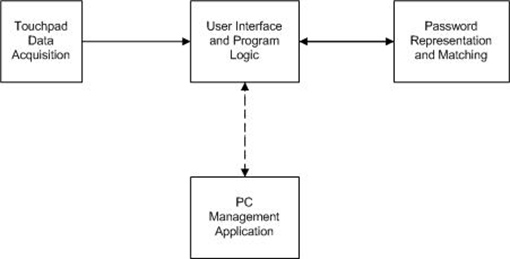
Figure 1. High Level Structure
The program logic entity is in charge of keeping the state of the system, managing the interaction with the user, instantiating the different entities, and controlling the interaction between them. The touchpad data acquisition unit is in charge of retrieving the finger position and pressure data in a raw format and transmitting it to the main program logic. The gesture representation and matching entity has the purpose of converting the raw data obtained from the touchpad into a logic representation and providing the comparison and matching between different gestures. Finally, the PC management entity provides the administrator with an easy tool to manage the device and look at the system events in real time.
System Specification
From a user point of view, the prototype is composed of a touchpad, two push buttons, two LEDs, and a USB connection. The following figure shows each component in the physical device:
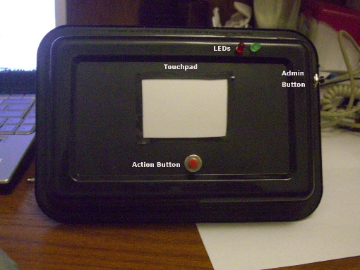
Figure 2. Prototype
To enter a password, the user must press the action button, then enter one or more symbols in the touchpad, and then press the action button again to finish the password.
The device can be used by two types of users: a regular user and an administrator. For the regular user, the password entering system is the only visible functionality. Once the user enters a password, the green LED flashes if the password was accepted, or the red one does if the password was rejected. For the administrator, the admin button is also visible and it enables him or her to actually set the password of the device. After pressing the admin button, the administrator is provided with administrator rights, and the next time a password is entered (again, using the action button), it is going to be recorded as the device password. Moreover, the administrator also has access to the usb connection with which the system can be monitored from a computer. Every action in the device, i.e. acceptance or rejection of users, is constantly sent and can be seen in a computer if the connection is enabled. Finally, if the device is connected via USB, the administrator also has the ability to set the password from the computer application, and look at the acceptance/rejection counts.
Hardware/Software Tradeoffs
The device uses only digital hardware elements and therefore the main tasks consist of handling each element with software implementations. All the program logic is implemented in software, and hardware elements are only used for data acquisition, signaling and communication.
In one specific case, however, we decided to use a hardware implementation of a functionality that could have been implemented in software. The functionality is the USB implementation for communicating to the PC application. We could have chosen to implement the USB protocol in the microcontroller and connect it directly to a computer. However, this decision would have increased the development time significantly without adding any extra value to the product. Instead, we decided to use a hardware chip that converts RS232 data into USB, and provides a driver to emulate a COM port in the PC. This way, development efficiency is increased because we are able to implement an easier serial communication on both the microcontroller and the PC side while still using the convenient USB interface in the middle.
We also considered using an LCD in the device to show interface messages such as "Enter password" and "Password accepted". From the software-implementation perspective, it did not represent any significant change. The tradeoff, in this case, was between cost and usability. Nevertheless, we considered that the device was easy enough so that after using it the first time the user should not need any extra help, and thus the LCD becomes redundant. For this reason, we simply used a couple of LEDs that indicate when passwords are accepted and rejected and saved some costs.
Standards
PS/2
Communication protocol used by certain types of peripheral devices such as mouse devices and keyboards. It's being replaced by USB but there are still multiple devices that use it nowadays. The Synaptics touchpad we chose uses the PS/2 protocol and therefore we needed to implement it in order to be able to communicate with the touchpad.
USB
Universal Serial Bus. One of the most popular protocols to establish communication between peripherals and host controllers, which are usually computers. In the project, we used USB as an intermediate link between the device and a computer.
Hardware
The following figure illustrates the high-level hardware distribution of the device.
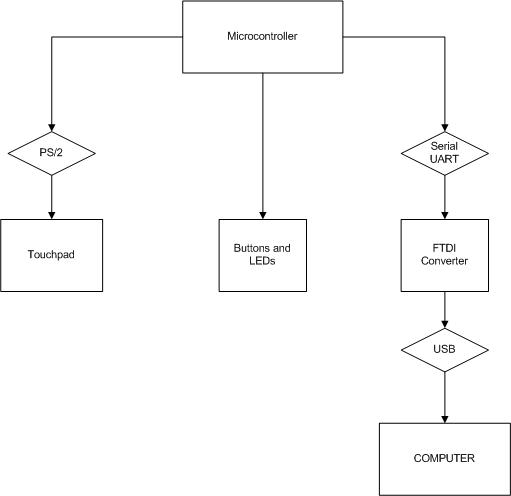
Figure 3. Hardware Distribution
Custom prototype board
We used one AVR Atmega644 microcontroller. For connecting to the microcontroller, we used a custom USB prototype board. The board is meant to be used for next year’s class, and an early version was obtained from Nathan Chun for use by our group. The PCB layout is shown in figure 4, and a schematic is shown in figure 5. The schematic lacks specific details on the USB converter chip and connector because they were unavailable. The board receives power from a wall plug which goes into a 5V regulator, the LM340LAZ-5.0. A switch on the side is used to turn the board on and off, and the microcontroller sits on a socket, from which its pins go out to header pins across the top of the board. A 16MHz crystal generates the clock, and a 1N4001 diode protects the regulator from reverse bias. The UART pins (D.0 and D.1) go to a FT232R USB converter chip, which then goes to a USB connector. The board we used was fully populated with all components, including capacitors, resistors, and all header pins.
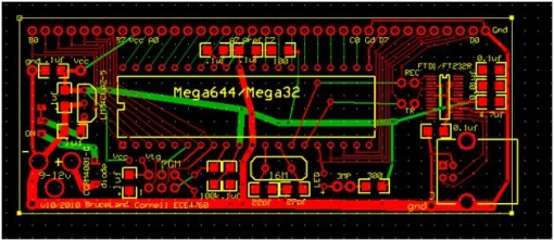
Figure 4.1 PCB Layout for the prototype board
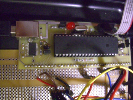
Figure 4.2 Full view of the USB prototype board
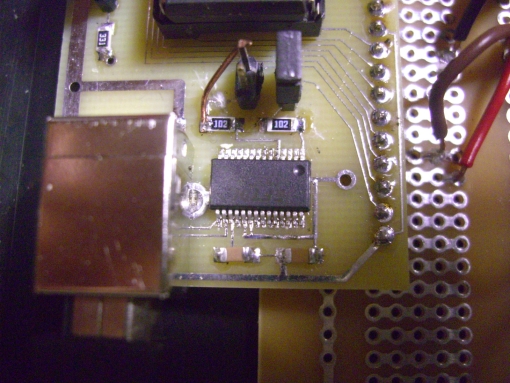
Figure 4.3 Close up of the FTDI Chip and USB Connector for prototype board
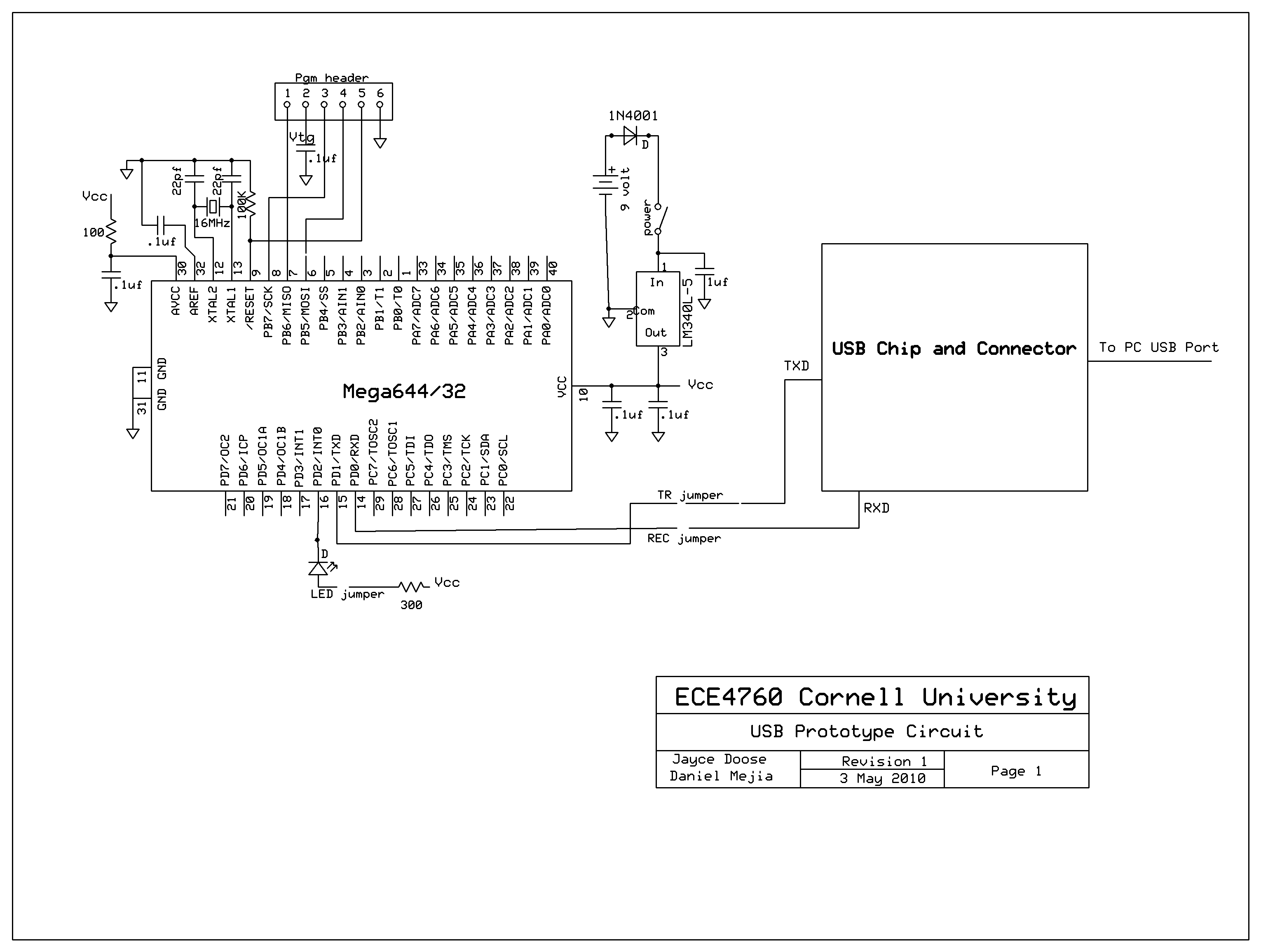
Figure 5. Prototype board schematic
Touchpad
We used a Synaptics touchpad whose specific reference is TM41PUM1311-2. At the selection stage, we found that Synaptics provided organized documentation for its older touchpads which could be very beneficial for communicating with the device and thus we chose to look for touchpads with their brand. We found a very cheap touchpad online that had been removed from a Dell laptop, and even though Synaptics did not have specific documentation for that reference, most of the specifications were very general, so we took the chance to try to make it work.
In terms of hardware configuration, the tricky part was to obtain the pinout of the device. The touchpad had a connector mounted to it, however it was determined that an appropriate adaptor for the connector would not arrive soon enough for testing purposes, and it was too small to solder wires directly on it. Instead, the touchpad was connected by soldering to a number of test points on the device, which were determined to be directly connected to the appropriate pins on the PS/2 connector. In the Synaptics documentation, there are a number of pinouts for various touchpad model types, but there was no inclusion of this model. By finding a resource that had already determined the 5V, data, and clock pins on the touchpad chip, we were able to confirm that the pinout corresponded to an existing touchpad in the documentation, and connect appropriately (fig. 6, 7).
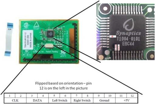
Figure 6. Touchpad Pinout
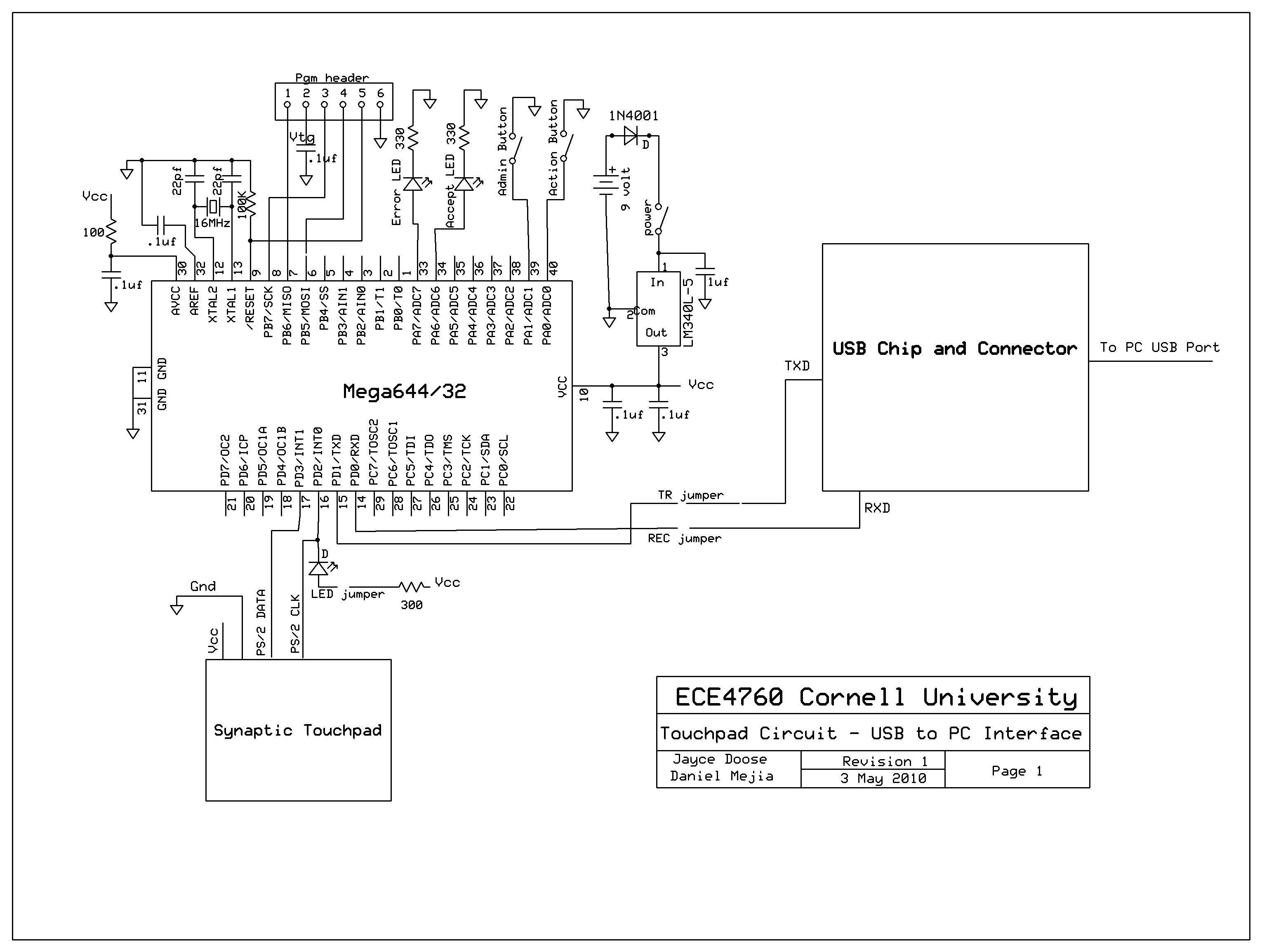
Figure 7. Touchpad - USB Interface Schematic
FTDI Converter
FTDI is a company specialized in USB technologies. It is well known for the implementation of RS232 and TTL serial transmissions to USB. We used a chip from FTDI whose reference is FT232R
The FT232R is an integrated circuit that provides a USB to serial UART interface. It handles the entire USB protocol on hardware, which completely releases the microcontroller from this task. This functionality enables an easy-to-implement communication with a computer. As mentioned before, this was one hardware/software tradeoffs in which we chose a hardware implementation to reduce code complexity and increase development efficiency. The chip was integrated with the prototype board we used, and hence we needed no extra hardware implementation to use it. The FTDI chip was, in fact, the reason for which we chose to use this specific board.
WIFI Module
One feature that we tried to implement was wifi communication between the device and a PC. Such a feature would prove extremely useful if there were a network of touchpad devices (perhaps each at a different door), all of which could be configured wirelessly by an administrator sitting at a PC, over the 2.4GHz band, which is freely available for use and would likely already be in use in many companies. Unfortunately this feature was not able to be made a functional part of our security device, due in part to it not functioning properly, and also because of its unreliability. However, it will be fully documented in this section and remains an area of future expansion for the device.
After extensive research on existing wifi modules on the market, and taking our budget into account, a WIZNET wifi module was chosen for the project, the WIZ610wi. Aside from being reasonably priced ($46 for the module and the antenna) the module promised plug and play functionality, in that it was optimized to provide easy wifi access from serial devices to PC’s. The device also featured impressive security options (supporting WEP, WPA, and WPA2 encryption), and could be configured as an access point, an Ethernet gateway, or a client.
Based on the recommendations made in the documentation, the module was configured as a client to our PC, and also configured such that if it received any data across the serial port, it would immediately send it to the PC, whose IP address was encoded as the permanent server connection for the module. Because our PC’s wireless card could not be reconfigured as an access point for the wifi module, a Netgear wireless router was used as an access point instead, and connected by Ethernet cable to the PC.
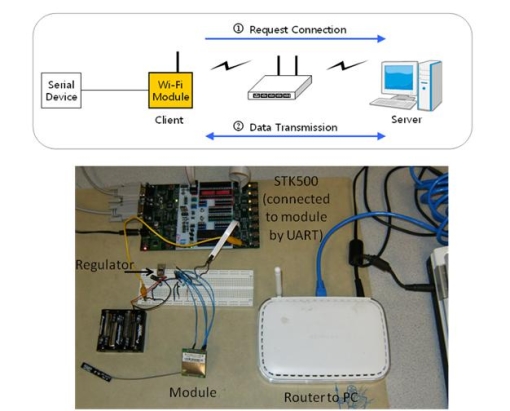
Figure 8. WIFI module connections
The module featured a 1.27mm connector that was originally soldered to, but which proved to be unstable. Thus, small pitch jumper cables were used instead. The only connections the module required to be able to transmit and receive serial data was power (3.3V), ground, and Sin and Sout (which are the receive and transmit of the UART serial communication) (fig. 9). Because the microcontroller runs at 5V, and because the module can draw up to 500mA or more of current, a 3.3V, 1A regulator (the AP1117) was used with four AA batteries in order to power the device. 10 µf and 47µf electrolytic capacitors were used in the regulator circuit in order to prevent voltage spikes. Similarly, because data coming from the microcontroller could have been 5V, and potentially damaged the wifi module, the input from the ATMEGA644 was voltage divided using a 100 ohm and 200 ohm resistor in order to limit the maximum voltage to 3.3V.
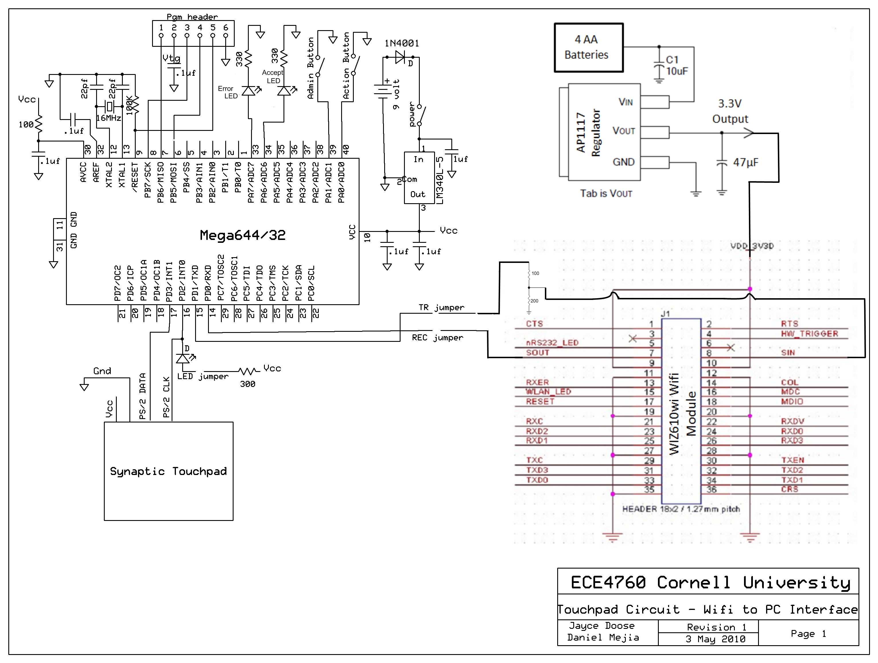
Figure 9. Schematic with WIFI module included
Although, according to the documentation, this was the required hardware and software configuration required for our application of the device, numerous problems were encountered. Although a reliable TCP socket connection could be made with the device, as evidenced by the wifi module’s MAC Address appearing on the “attached devices” menu of the wireless router (fig. 10), and by being able to access the module’s configuration page by pointing the PC’s browser to its IP address (192.168.1.254)
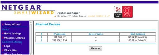
Figure 10. Router Configuration Page
Next, in order to see whether or not any data could be transmitted, a simple test program provided by Prof. Land in the first lab, wherein the microcontroller constantly outputs some timer information to the UART (TimersGCC644.c), was programmed to the microcontroller. Another program using the Java.net API, which allows for the programming of servers and establishing TCP socket connections, was created in order to read and print any data coming from the wifi module, and then send a simple string to the module. After running this program (TCPserver.java), this is the output:
Server has connected!
java.io.BufferedReader@addbf1
Sending string: 'Toobie ornaught toobie'
which established that the program had connected to the module, and sent and received information. That the string was sent was confirmed by using the packet sniffer program Wireshark, which clearly showed the packets being sent back and forth between the PC and module. The problem was that there were no data packets being sent to the PC from the module, even though the microcontroller was clearly sending data across the UART (as confirmed by oscilloscope and a HyperTerminal check).
A number of different debugging attempts were made, which included sending extensive setting documentation to WIZNET, the makers of the module, but from which they could not see that there were any immediate or obvious problems. Ultimately though it was discovered that one could telnet into the module, and that it ran LinuxNET4.0 on it as an operating system (fig 9). Thus, telnetting into the module allowed for direct observation of what was going across it’s serial interface, since this was believed to be where the problem lied. By executing the command: Cat /dev/ttyS0
Cat /dev/ttyS0
which represents the serial interface device for the module, then the entire contents of what was passing across the interface could be observed. In this file, when the MCU was running its timer program, the correct information did appear in the file.
Despite these advances in getting the module to function, two-way communication is still not operational at this moment, which is one of the reasons that it was not included in the project. Another reason is that the module is very unreliable – sometimes it will start up and immediately connect, and other times it will not connect after multiple attempts. Sometimes it is a power problem, and the batteries are too low for the module to function, but sometimes it will not connect to the router, despite fresh batteries, no shorts, and the module not having moved at all from when it was working just minutes before. Thus it was decided that the behavior of the module was too erratic and unstable to be included in the device, and that the USB interface would offer greater reliability.
Software
We believe in the importance of organized, self-contained, reusable code. Consequently, at the initial stages when designing the software structure, we tried to separate each functionality into independent modules that can be reused in other applications. For this purpose, we used the recommended programming practice in the C language of implementing APIs with well-defined interfaces that are specified in .h files, and provide the user with all the public functionalities while abstracting the implementation details contained in the .c files.
The software structure is illustrated in the following diagram:
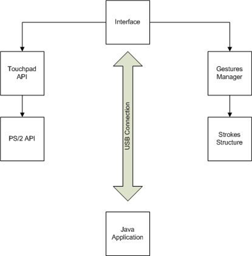
Figure 11. Software Structure
All the code for the microcontroller was implemented in C whereas the PC application was implemented using Java. Every microcontroller entity in the diagram corresponds to a pair of .c .h files, except for the interface entity which is implements the main logic and uses the functionalities provided by the rest of the modules. As we can see, the software organization matches very closely the high-level design shown in figure 1 which was our goal in terms of modularity.
PS/2 and Touchpad APIs
The touchpad uses the PS/2 protocol to communicate with a host. For modularity purposes, we chose to implement two separate APIs for PS/2 and the touchpad. The PS/2 API provides only the most basic transmission and reception functions whereas the touchpad API implements touchpad-specific functionalities that use the PS/2 protocol underneath. Some examples of these functionalities are touch information transmission, information queries, and configurations sequences. Furthermore, we implemented a structure that represents the absolute data packet provided by the touchpad, and included a function to parse the received bytes into this representation.
The touchpad API provides the access to the touchpad device, but it does not contain the actual touchpad handling we used for this project. This is placed in the interface file instead.
Interface
The file interface.c is the core software element of the device. It uses the functionalities provided by the APIs to create an interface for the user, and keeps track of the state of the system. It is also in charge of transmitting information to the PC management application, and recognizes asynchronous requests.
The main finite state machine implemented in interface.c can be seen in the following figure:
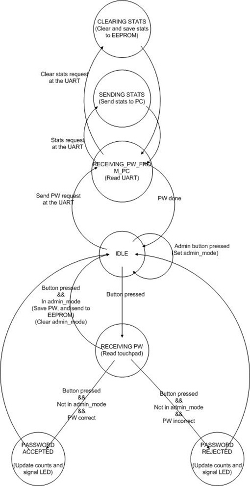
Figure 12. Main State Machine
As shown in the figure, the state machine shows a perfect fit with the specification provided in the high level design section. The convention used for the state machine is that routines called at a certain state or at certain transition are shown inside parenthesis. The device is by default in an idle state. While in the idle state, the touchpad is disabled from sending data, and the microcontroller constantly checks for any button-action received from the user. The only actions that cause a change of state are the user pressing a button, or a request received from the pc, through an UART interrupt. If the admin button is pressed, the program enters admin mode. If the action button is pressed, the touchpad is enabled, and the incoming data is periodically sampled. After the button is pressed again, one of two things happens: if the program is in admin mode, the device password is set to the entered password, and it is also sent to the EEPROM; if the program is not in admin mode, the password is compared to the current device password using the gestures manager, and the match or mismatch is shown by the LEDs. Also the admission/rejection counts are updated and saved to EEPROM.
At the UART, three types of commands can be received: SEND_PW, REQUEST_STATS, CLEAR_STATS. Depending on which command is received the program acts accordingly. For the SEND_PW command, the programs start receiving the password from the computer. With the REQUEST_STATS, the microcontroller sends the admission/rejection counts to the PC. Finally, with the CLEAR_STATS commands, the counts are cleared and saved to EEPROM.
In the interface implementation, another state machine was used for denouncing the buttons but its implementation is straightforward so its explanation was omitted. For implementation details, see the interface code.
The central interface file is also in charge of using the touchpad API to configure and obtain information from the touchpad. We configure the touchpad in absolute mode, which means that the touchpad sends absolute x and y positions as opposed to delta movements. Also, we used stream mode which means that the touchpad continuously sends data while it is enabled and it does not wait for a request-to-send packet. When receiving a password, the touchpad is enabled, and then an external interrupt is triggered after the touchpad pulls the clock line down. Then, the whole packet is received and the touchpad is inhibited until the data is processed. After recording the data (which happens at every sample period), the touchpad is re-enabled and another absolute packet is received. Note that the way to inhibit the touchpad is implemented in the touchpad and PS/2 APIs, and it consists of pulling the clock down.
Gestures and Strokes
The gestures unit only provides two relevant functions. The first one is intended to convert the data from the touchpad representation of the absolute packet to the actual data used in the matching process. The second function receives two gestures and returns if there is a match.
In order to accomplish a simple and effective matching algorithm, a data structure that represents the touchpad data in a more efficient and intuitive manner was implemented. This data structure is called stroke. A stroke represents each of the traces entered by the user without raising his or her finger. The stroke structure contains fields for the initial position of the stroke, a dynamic list of delta movements for x and y, and the wait time after the stroke, i.e. time until touching the touchpad again for a new stroke. To make the data more usable, we transform the received coordinates into a finite set of values that fits into a grid. The reasoning behind the decision is that the user cannot easily have precision for distances below the finger width, and therefore it does not make sense to take these differences into account when matching. Another advantage of this discretization is that we are able to change the 13 bit coordinate representation provided by the touchpad (which can only be fit into a 16-bit integer) into values that fit in byte variables (chars in C). Furthermore, the grid size we use is 32 by 24 and it gave good results. With these sizes, masking techniques can be used to save even more space in memory. Since we are sampling the touchpad data every 50ms, a good amount of data is involved and space saving techniques are important.
With this data structure, passwords are easily represented as arrays of strokes. More complicated techniques such as invariant moments were not applicable in this case, because we needed to capture both shapes and timing, and we were not interested in translation, rotation, or scale invariance. Also, we did not use absolute positions to represent the movement, because the error gets accumulated and provides a wrong intuition on the shapes involved.
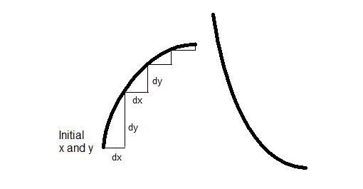
Figure 13. Strokes Representation
Since the stroke structure was created with matching as the main goal, the implementation of the match function is reduced to a comparison of the values in the stroke structure for each password. The distance for each stroke element between the two passwords is calculated and according to certain ranges it may pass or fail to me matched. The intuition is that as long as, for each stroke, the initial position is close enough, the movements are close enough, and the wait time is close enough, the password is accepted. These tolerance ranges are used as parameters that can be tuned for having a balance between security of the passwords, and usability of the system (the user being able to repeat his or her own password without great difficulties).
PC Management Application
The PC application provides the administrator with the three functionalities explained before. Looking at what's happening in the device in real time, setting the password, and reading the admission/rejection stats. Since the driver provided by FTDI for the USB converter emulates a serial port in the computer, before starting the application, we read the available serial ports from Java and present them for the user to choose.
Screenshots with the different functionalities of the application are presented next:
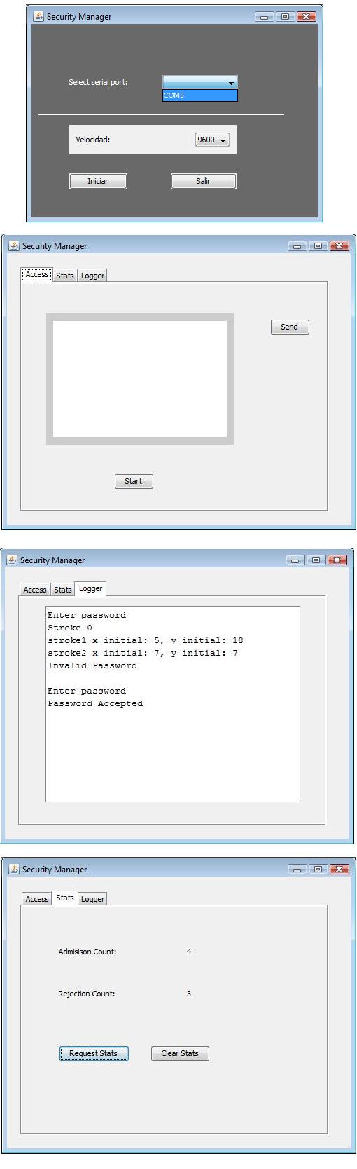
Figure 14. Management Application
As said before, we used Java to implement the application because of its multiplatform qualities, and our familiarity with the language. One thing to notice is that Sun does not provide support for the serial communications API in the windows operating system. Therefore, we needed to add an extra driver called win32comm.dll to the Sytem32 folder in windows.
The application comes ready to use at any computer and the installation instructions for Windows are the following:
- Install the Java virtual machine. Download the application here
- Place win32com.dll in the Java\jre(version)\bin and in the System32 folder
- Place comm.jar in the Java\jre(version)\lib\ext folder
- Place javax.comm.properties in the Java\jre(version)\lib folder
- Run IndacticSystem.jar which is in the dist folder
The application is not a final version. However, it is ready to use, and anyone can install it and monitor the device directly.
Results
The prototype we implemented can successfully receive passwords, store them, process them and compare them. We asked some friends to try it, and we obtained some very good feedback because everyone was able to create passwords and then repeat them in a way that was accepted by the system. Below are some videos demonstrating how the system works. The first shows a demo of just the touchpad device, while the second one focuses on the Java application.
As mentioned
earlier, we faced
a tradeoff between usability and accuracy of the passwords. We needed
to make our system secure enough so that passwords are not easily
stolen, but at the same time we need to provide a usable device that
would not frustrate users by making it too difficult to match a
password.
The obtained results after the testing process indicated that everyone was able to match a password. The first attempts could fail, especially until the user realizes that the position in which the symbol is traced, and the times used to enter it matter. Without counting the initial attempts, we had an efficiency of 93%, i.e. roughly 9 of 10 attempts to match a previously defined passwords were successful. The numbers were obtained by averaging the data taken from three friends using the device. They created a passwords, and then tried to match it 10 times.
We also tested how easy it was for other people to copy your passwords. If the other person only knows a description of the passwords, e.g. a square, the percentage of successful passwords copies was 0%. This means that a description of the passwords is not by any means sufficient to reproduce it. Finally, we tried letting someone see the password created by another person. Then we asked him to try to reproduce it, and with 10 attempts he was not able to do it. Then we let the person see the passwords again, and only at the 6th attempt it was able to input a correct password. We feel very satisfied with the results but even more parameter tuning can be done.
Conclusions
The implemented device satisfied each of our initial goals. We were able to implement a usable prototype that demonstrates the capabilities of the new security system approach we propose. The system works exactly as specified in the specification. Passwords are created, stored and matched, and we obtained positive feedback from the people who actually used the device and were able to match their own passwords.
We tried to add the additional feature of the WIFI connection, but for serious problems with the module, we were not able to implement the functionality. If we were to have the experience of re-implementing the device, we would do extensive analyses on the available options for WIFI functionality. We chose the module based on its price benefits and it apparent good and simple documentation. However, we did not consider the importance of company support. Unfortunately, the support provided for this module was minimal, and if were to buy another module we would sacrifice price in order to have a better customer service.
Nevertheless, we did implement the extra feature to monitor the device, and set the passwords from a computer. The only difference is that instead of using the wifi connection, we simply used the USB connection. The management functionalities are fully presented with the USB connection, and in the future the device could be extended to use them through a WIFI connection.
In terms of conformation to standards, we did not implement USB ourselves in the microcontroller. We used the FTDI chip, and they claim to comply with the USB standards.
As for the PS/2 protocol, we do not claim to have implemented a standard version of the protocol. Nevertheless, the API we used is functional, implements the basic data transmission functions, and anyone can reuse it by simply adding the files and including the ps2.h in the main c file.
Intellectual Property
We did not use someone else's code in our project. We implemented the code for every functionality in the project by ourselves. We did use the sample code in the touchpad documentation as a base to implement the PS/2 and touchpad APIs. Also, we implemented the serial port identification and selection by looking at the examples provided by Sun. Nevertheless both of these sources are public, so we do not have any intellectual property issues in this respect. Moreover, we did not reverse-engineered any design. We used the Synaptics touchpad according to the provided specifications.
In terms of publishing opportunities, we believe that we propose solid, and interesting ideas that can be explained in a paper and sent for publication. We need to do more research about which publishing entities are appropriate.
Finally, with the research we have done so far, we have not found specific implementations or proposals of gesture-based security systems that take timing into account. There are multiple patents for inputting symbols using touch devices, but none of the ones we have found uses the time dimension to implement a security system. Consequently, we could explore further and consider patent opportunities.
Ethical Considerations
This project does not pose any ethical problems, and all decisions were made in accordance with the IEEE code of ethics. This device does not pose any safety threats to its users. It is completely enclosed within a non-conducting plastic case and care has been made to ensure that the only items the user will interact with are the touchpad, pushbuttons, power plug, and USB plug, all of which are secure. There are no conflicts of interest associated with this project, since it is a class project for ECE 4760, and serves as a learning tool. The information stated within this report is honest. Some features were abandoned because they were unable to be fixed or debugged in time for the deadline, and our performance metrics for the touchpad’s level of gesture recognition are similarly honest in that there is not precise speed detection, and there is also a certain level of variability allowed for the password gestures to be recognized. Neither of us have encountered any form of bribery during this project, and would not accept bribes if offered.
In the course of this project, we have sought to improve the understanding of technology, it’s appropriate application, and potential consequences. The touchpad is an existing technology that is present on most laptops today, and through the application of this device as a security tool, rather than just a mouse replacement, we are seeking to further extend its normal application, which may have positive effects on individual’s security. We also acknowledge our limitations as engineers still in college, and do not claim to be experts in touchpad technology or password systems, but instead are willing to continue to improve our technical competence by taking on projects that extend our knowledge of existing technologies. In this process we have acknowledged and corrected the mistakes we’ve made, and been accepting of honest criticism of our design and our ideas. Similarly, we have properly acknowledged and referenced all those sources who have helped us in the course of this project. Our design does not discriminate toward any particular race, religion, gender, age group, or nationality. While those with certain types of disabilities may find this device difficult to use, they are not being discriminate against, it’s just the way that a person interfaces with the technology. For example, the blind, or those who have lost their hands - for them perhaps a voice-based password recognition system would be more appropriate. We have not sought to injure others or damage others projects by false or malicious actions, and we have always been glad to help fellow classmates whenever they have questions about our project or need to share a certain resource.
Legal Considerations
We ended up not using any transmitter devices in this project, thus there are no FCC regulations that apply. If the wifi module had worked, the 2.4GHz band is freely available for use, and there would not have been any FCC violations. The only other piece of hardware that requires legal consideration is the touchpad itself, since it is owned by Synaptics. On their website, Synaptics states that, “Customer agrees that it shall not reverse compile, disassemble or otherwise reverse engineer Synaptics' products.” In this case, because we are using the Synaptics published guide in order to understand how to use the touchpad for a particular application, we are not reverse engineering the device in any way, but instead using it as a Synaptics product. The determination of the pinout was also not a problem because the pinout was already published in the Synaptics touchpad documentation, just associated with a different model number. Thus, there are no legal problems with our project.
Project Information
This project was designed and implemented as the final assignment for the class ECE 4760 at Cornell University.