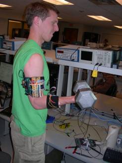
A wearable device that give the user tactile feedback to guide them through the proper execution of a bicep curl.
Michael Lyons – mpl56
Greg Meess – gdm26

Introduction
The goal of this project was to assist the user in learning the proper technique for a physical exercise, in our case a dumbbell bicep curl. As our understanding of biology and anatomy improves, the design of physical exercises is improved by the application of scientific principals and experimental results. For each exercise there is a known pace and kinematic pattern that yields optimal results. In practice however, it is often difficult to follow the prescribed motions. Thus our project was to create a wearable sleeve that coaches the user through the correct motion of a bicep curl. There is significantpotential impact of such a device on the world of bodybuilding or physical rehabilitation, because it will allow people to efficiently train in order to get the most out of their effort, instead of using excessive amounts of weight and poor form. More motivation for this project stems from the high cost of personal trainers who teach proper form and difficulty of maintaining the ideal pace of each exercise. The concept of a “haptic exercise coach” could fill a niche in the fitness market for self-paced learning ofexercises. Another exciting application is for physical therapy, where such devices could be particularly useful if the functionality was extended to capture and track data on the repetitions and range of motion achieved.
Rationale
The idea behind this project is through the user of sensors to guide a human into performing a bicep curl with the best form possible. The muscle group to be targeted by our device isthe bicep brachii.Our device will be tuned to check the form on one of the many variations on the dumbbell bicep curl.The sources for this idea were from videos seen describing the form of a dumbbell bicep curl on ehow.com, articles on form on bodybuilding.com, and finally details of the physics seen in Kinesiology of exercises from exrx.net. The reason for wanting to create a bicep curl guiding device is that when lifting weights it is important to maintain good form because it allows on to maximize the force being applied to a muscle group. In the case of the bicep curl especially, the form is crucial and frequently done wrong. The challenge with the bicep curl is that there are quite a few ways in which the curl can be performed incorrectly. On top of the large number of ways in which the bicep curl could be performed incorrectly there are also a large number of variations to the bicep curl. The first common mistake is for the person will bring the weight too high and too rapidly, which does not maximize the force on the actual bicep muscle. Bringing the weight past a one hundred degree angle of inclination will reduce the work load on the bicep curl, which defeats the purpose of the bicep curl in the first place. Another error to consider is the rate or pace in which the exercise is performed. If the bicep curl is performed too quickly it does not allow for enough contraction of the bicep muscle to work it appropriately. The next error often made during a bicep curl is that the wrist will change orientation. This change in orientation will cause other muscles, such as the brachiallis, to be used instead. Unless the wrist is oriented close to perpendicular, the force on the bicep brachiiis not maximized.
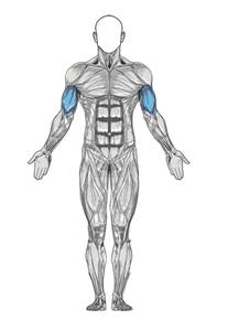
Figure 1: Target muscle group.
On top of the range of motion and wrist orientation, the orientation of your elbow is also of great importance. The elbow must remain stationary during the curl, because it is the pivot point on which all the force is applied from the weight in your hand to the bicep brachii muscle group. If the elbow were to move forward the force of the weight being held in your hand is not maximized on the bicep. The force in this case is not maximized because the force of gravity working on the weight is being shifted to reduce the amount of force on the bicep. This elbow movement usually occurs because the weight is too heavy for the maximum load capacity of the bicep muscle. Although intuitively it is best to lift the heaviest weight possible, when it causes poor form it is counter to the point of the exercise. The final errorthat is most often seen in the dumbbell bicep curl exercise is shifting the shoulder. The shoulder often moves up or down during the curl. The major problem with moving the shoulder around is that it shifts the entire apparatus used to perform the bicep curl, which can again reduce the load on the bicep muscle. The counterintuitive nature in this case stems from the use of momentum to move the weight to its maximum location. Another issue that can stem from shoulder motion is that one could shift each shoulder a different amount, which can lead to imbalances between the left and right sides of the body. Imbalance are a big issue because they place strain on your skeletal system and muscle in ways that lead to joint and muscle problems later in life. Imbalance in general should be avoided.
The overall goal of this project is to avoid the potential errors inlifting technique,and therefore maximize force for the best bicep curls. This is a much sought after device for those interested in bodybuilding because it will make the bicep muscle work harder allowing one to achieve a much better “pump” when they work out. The form correction will take the form of wrist, elbow, and shoulder orientation and position monitoring, which will also prevent muscle size and strength imbalances between the left and right side of the body with consistent form on both sides. Imbalances are not however, addressed to any great extent in this project because the budget would not allow for a sleeve on both arms.The optimization of the exercise will also occur through speed monitoring, which will force the user to have a long, slow contraction of the muscle in the region of largest load on the bicep muscle.
Form and load maximization will be achieved through a feedback system involving accelerometers and vibrator motors. An accelerometer is placed on the lower section of the arm. The purpose of this accelerometer on the wrist is to make sure that the user is notmoving the weight too quickly so that the contraction on the bicep is elongated. Also the accelerometer is going to make sure the user does not go too far past the point of maximum load on the bicep muscle. This accelerometer achieves these goals through feedback that is processed and then sent to three vibrator motors also placed on the lower arm. The vibrator motor on the top of the lower arm will notify the user when the rate of the bicep curl is too much, when the movement is at full extension, and just past the point of load maximization on the bicep muscle.The rate at which the bicep curl is to be performed is checked against a rate of about 1.7 radians per second which is the movement of the weight from full extension to one hundred degrees in just one second. The point defined as just past the point of load maximization is around one hundred to one hundred and ten degrees. The point of maximum load is at ninety degrees where the torque of the weight is maximized because torque is a function of sine.The rate checking of the bicep curl is done through a change in angle calculation in order to maintain a sufficiently low angular velocity. The two vibrator motors on the bottom of the lower arm will notify the user as to whether they are using correct form with respect to their wrists. If the wrist were to deviate in rotation too much in either direction the vibrator motors will go off notifying the user that they are not maximizing the load on the bicep brachii muscle and are using other muscles on the arm, such as the brachialis, instead. The rate and angle calculation are done in the software of the microcontroller. If the rate and angle results deviate too much from the ideal values the vibrator motor corresponding to that deviation will be activated.
The second accelerometer was placed on the upper arm to check the elbow and shoulder movement. This second accelerometer is also paired off with three vibrator motors. Each of these three vibrator motors correspond to a different direction in which the elbow could shift reducing the load maximization on the bicep brachii muscle. The three directions the elbow could move is first the forward direction toward the wrist, which will allow the user to use more momentum to move the weight up and down. The second direction in which the elbow could move is backwards away from the wrist which will reduce the range of motion of the bicep curl as well as the load maximization on the bicep brachii muscle. The final direction the elbow could move is in a sideways direction away from the body of the user. This final direction is the most important because the user is capable of bending the entire lower arm in the opposite direction which use move momentum and circumvent the use of the bicep muscle in order to move the weight up and down. Shifting the elbow in any one of these direction will be kept track of by the software on the microcontroller. In the microcontroller software feedback loop any deviation from the idea value from the accelerometer will result in the activation of the vibrator motor corresponding to the axis/direction of elbow shift.
There were not that many tradeoffs between the software and the hardware that we had to deal with in this project. The first tradeoff we had to deal with was the accuracy of the analog input. In order to get fairly linearly changing value we wanted to average a number of value recorded from the accelerometer which slowed down the software considerably. The averaging of the analog input takes over half the fifty millisecond period that the main loop of the program is allowed for execution. Another hardware/software tradeoff which was eventually worked out, was the eight bit versus the sixteen bit timers. The sixteen bit timer one needed to be set to simulate a fast eight bit timer in order to line up the PWM channel outputs between all six different vibrator motors. If this had not been done the vibrator motors on the PWM channels of timer one would vibrator with significantly less force than the other vibrator motors.
Sources:
Good video on the proper form of dumbbell bicep curl:
http://www.ehow.com/video_2359873_dumbbell-weight-lifting-exercise-beginners.html
Dumbbell bicep curl form description:
http://www.bodybuilding.com/exercises/detail/view/name/dumbbell-bicep-curl
Physics of weight training:
http://www.bodybuilding.com/fun/becker2.htm
How weight lifting has everything to do with physics:
http://www.scoobysworkshop.com/physics.htm
Precise bicep curl form description:
http://www.stumptuous.com/biceps-curl
Kinesiology of a bicep curl:
http://www.exrx.net/Kinesiology/AnglePull.html
Program/Hardware Design
The high level design of the software was to first initialize the microcontroller to setup six different analog inputs, all six pulse width modulator channels, the uart for debugging statements, and enabling the timer zero overflow vector. After the microcontroller components were initialized the timer zero overflow vector continually decrements the variable called the accumulator to zero. The accumulator is set to a high value of twelve which results in a running period of roughly forty nine to fifty micro-seconds which is the time base under which all our calculations are done. While the accumulator is being decremented the program enters its main loop and checks to see if the time based time period is up. If the time base period is up then the program reads in its analog inputs and stores their values as characters in universal variables. The program then execution its feedback control where it checks all the important parameters of the upper arm and the lower arm which are a number of different angles, and speed of exercise execution. Each parameters value is checked against base values that are calculated by from the ideal rates and degrees of freedom we thought were appropriate. Depending on where the analog input value lands the pulse width modulator period is adjusted to cause the corresponding vibrator motor to vibrate at increasingly high speed to indicate how far the user is deviating from the ideal form of the bicep curl.
The overall system architecture of our device is relatively straightforward. As shown in the figure 2 below, there are only two interfaces between the hardware and software, an input and an output. After initializing, the code enters a continuous loop. On each iteration of the loop, the software reads the analog voltages from the accelerometers, then calculates and sets the appropriate motor speeds to provide user feedback. This whole process takes place at 20 Hz, which is fast enough to provide seamless operation from a human viewpoint.
Figure 2: System Architecture
The software was
setup similar to that used in the labs for the ece476 class where the correct
Mega32 chip was selected and the clock speed was set to 16 MHz.The code was
written mainly in C in the CodeVisionAVR IDE.
Included Files:
#include
<inttypes.h>
This was included
for the purpose of using the printf() function for debugging the code.
#include
<avr/io.h>
This was included
for input and output enabling for the microcontroller.
#include
<avr/interrupt.h>
This was included
so that interrupt service routine could be used.
#include
<stdio.h>
This was included
for the purpose of a few important functions for the purpose of debugging the
program.
#include
"uart.h"
This was included so
that the print output of the function could be place into the hyper terminal.
#include
<math.h>
This was included
because some math functions, such as atan, were important in the calculation
needed for the feedback loop.
Function
declaration:
void initialize(void)
This function was
used to setup the microcontroller so that all the ports, timers, interrupt
service routines, and pulse width modulators.
voidreadAccel(void)
This function was
used to read in the all six analog inputs from the accelerometers and average
them to be used in calculations used in the feedback loop.
voidmotorControl(void)
This function was
used to take the calculations of the necessary parameters of the arm and use
them to change the output of the corresponding PWM channel.
To see how the
code works in great detail we need to follow the execution of the software. Execution
begins at the top of the main function where the initialize function is run.
The structure of the initialize function is shown below in figure 3. To start
off the initialize function port A is set to an input which is done by setting
up the analog input on the port. The analog input is enabled by setting the ADC
left adjust result bit to one of the ADMUX register. Also the MUX0 bit of the
ADMUX register is set to one to set the gain of the analog input. Next the
analog input is enabled by setting the ADEN bit of the ADC control and status
register. Also the ADC start conversion bit is set to one to start the analog
conversion. After the analog inputs on port A is enabled the uart is enabled so
that during testing we could debug the code by reading appropriate parameters
to the hyperterminal. A printf statement is then used to show that the program
is executing. Next the data direction registers are set for the PWM channel
outputs. The pin set to outputs are B.3, B.4, D.6, D.7, D.4, and D.5. Next the
prescalars, through timer counter control register B, for timers zero and one
are set to four which corresponds to a division of the clock speed by 1024. The
timer counter control register for timers one is setup differently here because
we need to set the timer to run in fast 8-bit mode. Running in fast 8-bit mode
is necessary because the output of the PWM channel would have a different
magnitude going with our time base of ~50 ms.The prescalar of timer one is also
set to 1024. Next the timer zero overflow interrupt service routine is enabled.
The accumulator variables used in the timer zero overflow ISR is initialized
and the ISRs are cranked up.

Figure 3: "initialize" function outline
Next in the main
function the main loop is begun and we wait for the appropriate time base to
complete before we continue program execution. The time based is established by
using the timer zero overflow interrupt service routine which requires twelve
cycles of 4.1 milliseconds to complete before the program is run again. This
allows for synchronous and easy calculations of the arm position and change in
angle. After checking the time base the readAccel() function is called which
reads in all six analog inputs from the accelerometers into their corresponding
global variables.
The readAccel()
function, displays in figure 4, sets the
ADMUX registerand ADC control and status register which starts the conversion
on all six analog inputs. The program then waits till the conversion is
complete and reads the value into a char with the appropriate name of the axis
being measured on the upper or lower arm. Ten of these analog inputs are
recorded and then they are averaged for very accurate and smoothed results for
good feedback purposes. The average values are then scaled based on a
calibration function developed from data taken on each accelerometer’s angle
sensitivity with respect to each axis. Then the relevant angles are calculated
using an arctangent function and stored in global variables. The angles we care
about on the upper arm are the angle between the x and y axis, and the z and y
axis. For the lower arm we care about the angles between the z and x axis, and
the z and y axis. These angles are calculation based on the forces in the g
field measured by the accelerometers.

Figure 4: "readAccel" function outline.
The program then
returns to the main loop where it enters the motorControl() function, which is
displayed in figure 5. Here the control is separated between the upper arm and
lower arm vibrator motor outputs. For the upper arm the angle between the z and
y axis is checked in the negative range. If the angle exceeds negative thirty
degree then the output of the PWM channel to side of the upper arm is set to
full. If the angle is between negative fifteen and thirty there is a linear
scaling function of increasing magnitude to notify the user of incorrect
position of the elbow. This guarantees that the user is not swinging and using
momentum to lift the weight.Next the angle between the x and y axis is checked
and if it exceed positive thirty then the output to the front of the upper arm
is set to full. If the angle is between thirty and zero then a linear scaling
function is used to run the pager motor. This guarantees that the user is
keeping the force load maximized on the bicep muscle. Finally on the upper arm
the angle between the x and y axis is checked to see if it exceeds negative
forty degrees the PWM channel is set to the maximum value. If the angle is
between negative twenty and forty then a linear scaling function is used for
the output to the pager motor. This section of code makes sure that the elbow
and shoulder are not shifting outward to keep the pivot point of the weight
stationary which allows for the force produced by the weight through gravity to
be counter acted entirely by the bicep brachii muscle.
The next section
of the motorControl() function keeps track of the movement and positioning of
the lower arm. Here a calculation of the change in the angle between the z and
y axis is needed so that the rate of the bicep curl can be kept track of. The
first condition checked at this point in the angle between the z and x axis. If
the angle is greater than negative seventy and less than negative fifty degrees
then a linear scaling function is used for the output to the pager motor. If
the angle exceeds negative fifty degrees the output to the pager motor is set
to its maximum value. This purpose of this vibrator motor is to make sure that
the wrist is remaining perpendicular to the forearm. Any rotation in the wrist
changes the positioning of the muscles in the arm. This change in position can
result in other muscles, such as the brachialis to be used instead of the bicep
brachii muscle which deviate from the dumbbell bicep curl variation that we are
testing. Next the same angle is checked but the variation in the opposite
direction. The angle in the opposite direction is less likely to go awry
because it is difficult for most people to move their wrist too far in this
direction but the condition should be checked for complete form analysis. In
this case if the angle is less than forty then the pager motor output is set to
full. If the angle is between forty and sixty then a linear scaling function
for the output is used. The final condition checked in this low arm section is
the change in angle between the z and y axis which is the angle on which the
movement of the weight is executed. Here if the change in angle per fifty
millisecond time divisions is greater than five degrees and less than twelve
degrees a linear scaling function is used to the output of the pager motor on
the top of the lower arm. If the change in angle exceeds twelve then the output
to the pager motor is set to full. The negative version of these change in
angle is also checked with the same methodology. This part of the lower arm
code is not display in figure 2.
Once the
motorControl() program completes the time base is run out and the next cycle of
analog inputs and motor outputs are set allowing for a slow and perfect
execution of the dumbbell bicep curl to maximize the load on the bicep brachii
muscle.
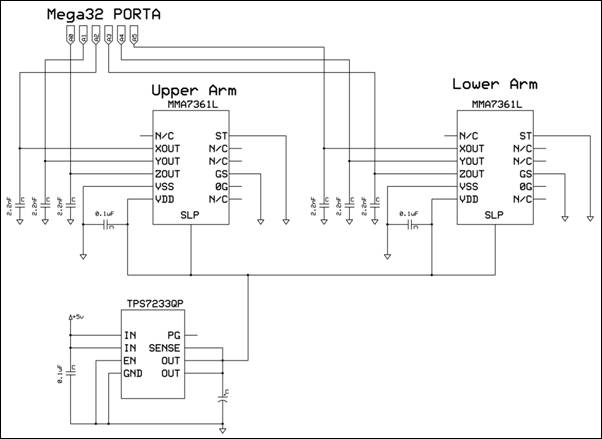
To look more in detail at the hardware we used a microcontroller, accelerometers, pager motors, voltage regulators, 1k resistors, BUZ73 CMOS, and diodes.The accelerometer circuit used in our project is shown below in figure 5. In the accelerometer interface six ports on the microcontroller were initialized to take in six analog inputs and were then used by the software to guide the feedback system. The analog inputs used port A.0 through A.5 where ports A.1, A.3, and A.5 were used for the accelerometer readings from upper arm and the remaining ports A.0, A.2, and A.4 were used for the accelerometer readings from the lower arm. These ports outline the interface between the microcontroller and the outputs from the accelerometers but powering the accelerometers involved a little extra hardware. The extra hardware needed was a voltage regulator circuit. The circuit used was for the Texas instruments TPS7233QP power regulator which powers the accelerometers at 3.3 V. Additionally in order to run this power regulator the circuit shown in figure 7 from the data sheet for this chip was setup.
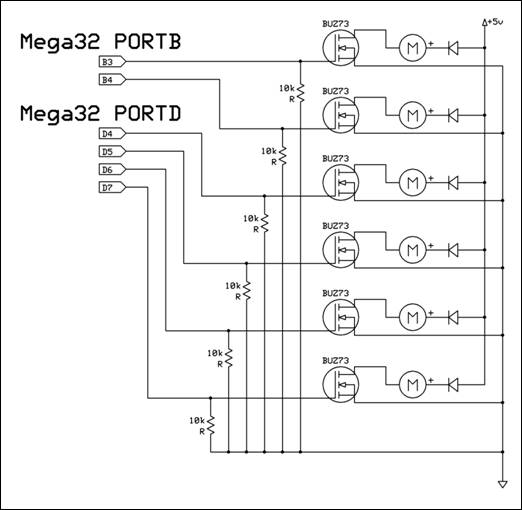
The next part of the hardware we will discuss is the pager motor circuit used for feedback to the user of our device. This section of the hardware, as shown above in figure 2, is separated by the interface to the software from the accelerometer hardware. The pager motors were chosen to be powered by the six PWM channel outputs from the microcontroller. Each timer on the microcontroller has two PWM channels. The output of the PWM channel is dependent on the analog inputs from the accelerometer hardware outputs and calculations done by the software. The PWM channel output is outputted on either pin B.3, B.4, D.4, D.5, D.6, or D.7 depending on the location of the pager motor on the arm. In order to power these motor directly without causing them to overheat we created a circuit which is shown below in figure 6. From the pin the output of the PWM channel is put through a one kilo-ohm resistor to ground and to the gate of a CMOS BUZ73 chip. Depending on the output of the PWM channel the BUZ73 allows the Vcc voltage to flow through the diode and then through the pager motor to ground. The higher the period of the PWM channel the more voltage will pass through the pager motor increasing the amount of force felt by the user. The voltage from the vibrator motor flow through the BUZ73 from drain to source and the source is then connected to ground. The maximum voltage, and thus the maximum force provided by the motor, allowed by the vibrator motor is 4.5 V which is slightly less than Vcc of five volts. We tested the pager motors at this higher voltage range and the temperature of the pager motor became fairly hot and thus the circuit was implemented in order to maintain safe operating temperatures to protect the user. The circuit allowed for a maximum voltage of 4.1 V which satisfies safe operating range for the user.

Figure 5: Accelerometer interface.
Accelerometer Connections:
ST
self test
0 V
GSEL g select
0 V
OGD 0 g detect NC
SLP sleep mode 3.3
V
XOUT x-acceleration Pin A.1
YOUT y-acceleration Pin A.3
ZOUT
z-acceleration Pin A.5
GND ground
0 V
VCC voltage supply 3.3 V
Figure 6: Motor driver circuit.
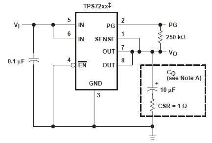
Figure 7: Power Regulator circuit
Results
During testing and debugging, an obvious flaw in the physical sleeve became apparent; despite being nearly too big for Greg, it was too small to fit around Michael’s arm. A final product would need a stretchier material or adjustable strap to make it one-size-fits-all. Otherwise, the neoprene worked well as a base for the electronics. It provided good protection for the user, both from electrical shocks and from irritation by the sharp features on the underside of the circuit boards. The potential risk of electric shock and uncomfortable temperatures were avoided through the use of insulating materials. The thread used to hold some of the circuit pieces to the neoprene sleeve was not durable enough and broke several times. Also jumpers to connect the vibrator motors to their outputs on the microcontroller needed to be reinforced with solder so that they would remain connected during extensive workouts. The interface for this device is fairly intuitive to follow;you undergo the dumbbell bicep curl and avoid setting the vibrator motor from going off. By interpreting vibration as a gentle push, it quickly began to feel like a real push. Even if you knew nothing about the exercise beforehand you could figure out the form from using the sleeve over a period of time. Interference was not a problem in the use of this device because all connections are wired directly to each other, so no wireless interference was experienced. Finally the speed of execution was roughly every fifty milliseconds,which allowed for sufficiently accurate calculation of angles and angular velocity. The accuracy and conditions for the feedback loop did need to be relaxed for the final design because human motion is prone to undergo quite a few slight changes but general form feedback was achieved with proficiency.
Conclusions
The goals for our project were achieved; a self-contained unit that performed as we had hoped.
Although our arrangement was adequate for our prototype, which coached a single exercise, the concept could be expanded to a total-body system. With sensors on both legs and both arms, it would be possible for the device to coach almost any exercise. It would be cumbersome and perhaps even hazardous for the user to have wires running all over their body; however, it would be possible to use tiny, short-range RF receivers and transmitters to eliminate the connections between the different locations, and allow the bulk of the processing to take place on a separate device. This would allow for much greater storage space for different exercises, as well as more sophisticated feedback algorithms.
This concept has potential for positive societal impact. Beyond the appeal for athletes and bodybuilder, patients undergoing physical rehabilitation could be greatly aided by such a device. Given that improper technique often leads to reinjuries, and the expense of full-time attention from personal trainers, a haptic feedback device such as ours could fill a currently unmet market. Also, given the popularity of video games such as Dance Dance Revolution and Guitar Hero, adding a similar element of physically matching a specified pattern may encourage more people to partake in physical exercise. Electronic feedback systems exist for Olympic weightlifters, but use visual feedback and only monitor tilt in one direction. As such, we believe a more polished version of our prototype device would fill a currently unmet need, and it may be worth pursuing a patent.
This project used some code from previous labs in ece476. The code sections that were either reused or influenced by were the analog input and the pulse width modulator outputs. This code was modified to a good extent to meet our needs but was influenced by the labs in ece476. No code was used from a public domain. Reverse engineering was not used in the development of this project. The devices we used all came with data sheets that appropriately explained features and parameters of each device we used. No apparent legal or ethical considerations were found with this project.
Appendix
Schematics
Accelerometer Circuit Schematic
Pager Motor Circuit Schematic
Purchased Parts List
|
Description |
Part
Number |
Source |
Qty. |
Cost
(unit) |
Cost
(total) |
|
Triple-Axis
Accelerometer & Breakout |
SEN-09652 |
Sparkfun |
2 |
$19.95 |
$39.90 |
|
Pager
Motor |
DCM-371 |
All
Electronics |
6 |
$1.25 |
$7.50 |
|
9V
Battery |
- |
Radioshack |
1 |
$0.69 |
$0.69 |
|
Elbow
Brace |
- |
Wegmans |
1 |
$7.95 |
$7.95 |
|
Mega644 |
- |
Lab |
1 |
$8.00 |
$8.00 |
|
Custom
PC Board & Components |
- |
Lab |
1 |
$4.00 |
$4.00 |
|
Barrel
Plug |
- |
Lab |
1 |
$1.00 |
$1.00 |
|
RS232
Connector |
- |
Lab |
1 |
$1.00 |
$1.00 |
|
Solder
Board (6") |
- |
Lab |
1 |
$2.50 |
$2.50 |
|
Total: |
$72.54 |
Scrounged Parts List
|
Description |
Qty. |
|
BUZ72 |
6 |
|
10k
Resistor |
6 |
|
TPS7233QP
Voltage Regulator |
1 |
|
10
μF Capacitor |
1 |
|
0.1
μF Capacitor |
1 |
|
Wire |
- |
|
Black
Thread |
- |
|
Ribbon
Cable |
- |
Calibration Data and graphs for Accelerometers:
|
Accelerometer
Tests - 2.56 Comparator Voltage |
||||
|
Theta |
g |
Vx |
Vy |
Vz |
|
0 |
1.000 |
247 |
250 |
236 |
|
10 |
0.985 |
246 |
248 |
235 |
|
20 |
0.940 |
243 |
244 |
230 |
|
30 |
0.866 |
237 |
238 |
223 |
|
40 |
0.766 |
229 |
234 |
216 |
|
50 |
0.643 |
221 |
223 |
206 |
|
60 |
0.500 |
209 |
209 |
194 |
|
70 |
0.342 |
195 |
199 |
184 |
|
80 |
0.174 |
181 |
188 |
171 |
|
90 |
0.000 |
168 |
172 |
156 |
|
100 |
-0.174 |
153 |
156 |
144 |
|
110 |
-0.342 |
134 |
141 |
131 |
|
120 |
-0.500 |
123 |
128 |
119 |
|
130 |
-0.643 |
111 |
117 |
109 |
|
140 |
-0.766 |
105 |
106 |
95 |
|
150 |
-0.866 |
98 |
99 |
89 |
|
160 |
-0.940 |
92 |
92 |
83 |
|
170 |
-0.985 |
88 |
90 |
80 |
|
180 |
-1.000 |
86 |
89 |
76 |

Work Division
Greg Meess –physical construction, design
Michael Lyons – design, code
Software Listing
/************************************************************
HAPTIC EXCERCISE COACH
Michael Lyons
Greg Meess
This program is for testing
the upper arm part of the
bicep curl machine. This
program is a combination of the
accerlerometer and vibrator
motor test program. Information
about both of these program
is given below.
Accelerometer test program
This program acquires all
three the analog outputs from the
accerlerometer.
Vibrator Test program
This program sets up six channels
worth of PWM outputs to run
each of the six vibrator
motors separatly at different levels.
************************************************************/
#include <inttypes.h>
#include <avr/io.h>
#include
<avr/interrupt.h>
#include <stdio.h>
#include "uart.h"
#include <math.h>
// UART file descriptor
// putchar and getchar are
in uart.c
FILE uart_str =
FDEV_SETUP_STREAM(uart_putchar, uart_getchar, _FDEV_SETUP_RW);
//I like these definitions
#define begin {
#define end }
#define PI 3.14159265
//A to D inputs from
accerlerometers
volatile char
UXin,UYin,UZin,LXin,LYin,LZin; //raw
A to D number
//A to D inputs average
variables
volatile float
UXavg,UYavg,UZavg,LXavg,LYavg,LZavg;
//calculation of g force on
each axis
floatUXg,UYg,UZg,LXg,LYg,LZg;
//angles needed to keep
track of form
volatile float
UXYangle,UZYangle,LXYangle,LZYangle, LZXangle;
//storage variables to tell
the rate at which the bicep curl is being executed
volatile float lastLZXangle,
lastLZYangle;
//rate at which the bicep
curl is being done
volatile float deltaZXangle,
deltaZYangle;
//for loop counter variable
int i;
//accumulator variable
volatileint accumulator = 0;
//function initalization
void initialize(void);
voidreadAccel(void);
voidmotorControl(void);
//===========================================================================
//**********************************************************
// timer 0 capture ISR
ISR (TIMER0_OVF_vect)
begin
if(accumulator > 0) begin
--accumulator;
end
end
//**********************************************************
int main(void){
//initialize the
microcontroller
initialize();
//zero angles
lastLZXangle = 0;
lastLZYangle = 0;
deltaZXangle = 0;
deltaZYangle = 0;
while (1){
if (accumulator == 0) begin
//analog inputs are read
readAccel();
//adjusts the amount of
vibration each motor outputs
motorControl();
//variables used for change
in angle calculations
lastLZXangle = LZXangle;
lastLZYangle = LZYangle;
//reset the time base
accumulator = 12;
end
}
}
//===========================================================================
void initialize(void){
//init the A to D converter
//channel zero/ left adj /EXTERNAL Aref
//!!!CONNECT Aref jumper!!!!
ADMUX =
(1<<ADLAR)|(1<<MUX0);
//enable ADC and set prescaler to
1/128*16MHz=125,000
//and clear interupt enable
//and start a conversion
ADCSRA = (1<<ADEN) | ((1<<ADSC)
+ 7);
// init the UART -- uart_init() is in uart.c
uart_init();
stdout = stdin = stderr =
&uart_str;
fprintf(stdout,"Starting
ADC demo...\n\r");
//create outputs
// make B.2-7 outputs
DDRB =
(1<<PINB3)|(1<<PINB4);//|(1<<PINB2)|(1<<PINB4)|(1<<PINB5)|(1<<PINB6)|(1<<PINB7);
DDRD = (1<<PIND6) | (1<<PIND7) |
(1<<PIND4) | (1<<PIND5);
//set up INT0
//EIMSK = 1<<INT0 ; //
turn on int0
//EICRA = 63 ; // rising edge
// turn on timer 2 to be
read in int0 ISR
TCCR2B = 4; // divide by
1024
TCCR0B = 4;
TCCR1B = (1<<CS12) |
(1<<WGM12);
// turn on timer 2 overflow
ISR for double precision time
//timer count register
TCNT0 = 255;
TCNT1 = 255;
TCNT2 = 255;
// turns on PWM
TCCR0A = (1<<COM0A1) |
(1<<COM0B1) | (1<<WGM00) | (1<<WGM01);
TCCR1A = (1<<COM1A1) |
(1<<COM1B1) | (1<<WGM10);//(1<<WGM11) | ;
TCCR2A = (1<<COM2A1) |
(1<<COM2B1) | (1<<WGM21) | (1<<WGM20);
//turn on timer 0 overflow
ISR
TIMSK0 = (1<<TOIE0) ;
//accumulator
accumulator = 0;
//crank up the ISRs
sei();
}
//===========================================================================
voidreadAccel(void){
//reinitialize local average
for sampling
UXavg = 0;
UYavg = 0;
UZavg = 0;
LXavg = 0;
LYavg = 0;
LZavg = 0;
for(i=0;i<10;i++){
//analog inputs from port A
ADMUX =
(1<<ADLAR)|(1<<REFS0)|(1<<REFS1);
ADCSRA |= (1<<ADSC);
while((ADCSRA &
(1<<ADSC)) != 0){};
UZin = ADCH;
ADMUX = (1<<ADLAR)|(1<<MUX0)|(1<<REFS0)|(1<<REFS1);
ADCSRA |= (1<<ADSC);
while((ADCSRA &
(1<<ADSC)) != 0){};
UYin = ADCH;
ADMUX =
(1<<ADLAR)|(1<<MUX1)|(1<<REFS0)|(1<<REFS1);
ADCSRA |= (1<<ADSC);
while((ADCSRA &
(1<<ADSC)) != 0){};
UXin = ADCH;
ADMUX = (1<<ADLAR)|(1<<MUX0)|(1<<MUX1)|(1<<REFS0)|(1<<REFS1);
ADCSRA |= (1<<ADSC);
while((ADCSRA &
(1<<ADSC)) != 0){};
LZin = ADCH;
ADMUX =
(1<<ADLAR)|(1<<MUX2)|(1<<REFS0)|(1<<REFS1);
ADCSRA |= (1<<ADSC);
while((ADCSRA &
(1<<ADSC)) != 0){};
LYin = ADCH;
ADMUX =
(1<<ADLAR)|(1<<MUX2)|(1<<MUX0)|(1<<REFS0)|(1<<REFS1);
ADCSRA |= (1<<ADSC);
while((ADCSRA &
(1<<ADSC)) != 0){};
LXin = ADCH;
//sample averager
UXavg += UXin/10.0;
UYavg += UYin/10.0;
UZavg += UZin/10.0;
LXavg += LXin/10.0;
LYavg += LYin/10.0;
LZavg += LZin/10.0;
}
//g force scaling and
calculation for upper arm
UXg =
100.0*(UXavg*0.0127-2.1131);
UYg =
100.0*(UYavg*0.0123-2.0932);
UZg =
100.0*(UZavg*0.0124-1.9967);
UXYangle =
atan(UXg/UYg)*180/PI;
UZYangle =
-atan(UZg/UYg)*180/PI;
//g force scaling and
calculation for lower arm
LXg =
100.0*(LXavg*0.0127-2.1131);
LYg =
100.0*(LYavg*0.0123-2.0932);
LZg =
100.0*(LZavg*0.0124-1.9967);
//calculates necessary angle
for bicep curl based on g
//force calculated above
LZXangle = atan(LZg/LXg)*180/PI;
LZYangle =
-atan(LZg/LYg)*180/PI;
}
//===========================================================================
voidmotorControl(void){
//Upper Arm Adjustment code
// Upper Arm - Side angle
check
if(UZYangle> -15.0){
OCR1A = 0;
}else if(UZYangle<
-30.0){
OCR1A = 255;
}else{
OCR1A =
(int)(UZYangle*255.0/30.0);
}
// Upper Arm - Front angle
check
if(UXYangle< 0.0){
OCR2B = 0;
}else if(UXYangle> 30.0){
OCR2B = 255;
}else{
OCR2B =
(int)(UXYangle*255.0/30.0);
}
// Upper Arm - Back angle
check
if(UXYangle> -20.0){
OCR1B = 0;
}else if(UXYangle<
-40.0){
OCR1B = 255;
}else{
OCR1B =
(int)(-UXYangle*255.0/30.0);
}
//Lower Arm Adjustment code
deltaZYangle = LZYangle -
lastLZYangle;
//lower arm YAW check
if(LZXangle< 0.0)begin
if (LZXangle< -70.0)
begin
OCR0B = 0;
end
else if (LZXangle< -50.0
&&LZXangle> -70.0) begin
OCR0B = (int)
((-1.0)*LZXangle*255.0/20.0);
end
else begin
OCR0B = 255;
end
end
if(LZXangle>0.0)begin
if (LZXangle> 60.0) begin
OCR2A = 0;
end
else if (LZXangle>40.0
&&LZXangle< 60.0) begin
OCR2A = (int)
(LZXangle*255.0/20.0);
end
else begin
OCR2A = 255;
end
end
//lower arm rate of curl
check
if (deltaZYangle> 5.0
&&deltaZYangle< 12.0) begin
OCR0A = (int) (deltaZYangle
* 255.0 / 5.0);
end
else if (deltaZYangle>
12) begin
OCR0A = 255;
end
else begin
OCR0A = 0;
end
if (deltaZYangle< -5.0
&&deltaZYangle> -12.0) begin
OCR0A = (int)
((-1.0)*deltaZYangle * 255.0 / 5.0);
end
else if (deltaZYangle<
-12.0) begin
OCR0A = 255;
end
else begin
OCR0A = 0;
end
}