
Introduction
Mister Gloves is a wireless USB gesture input system that enables a person to use a computer by performing intuitive hand and finger motions in the air. While wearing a glove controller on the right hand, the user can move the cursor by forming a pointing gesture and click by curling the index finger or thumb. Other right hand gestures enable scrolling and provide access to various keyboard shortcuts. Wearing a glove device on the left hand allows the user to type different keys through a combination of tilting the hand and touching different portions of the palm and fingers with the thumb. The left and right controllers are attached to each other but communicate to the computer wirelessly through a base station. Mister Gloves uses a low-speed USB 1.1 interface and does not require the installation of additional drivers.
Our gesture input system can be conveniently used by anyone who wishes not to be tied down to a desk when using a computer, making it perfect for giving presentations or web surfing from the couch. The intuitive hand motion controls also allow it to serve as an alternative video game controller. Additionally, since our input system does not exert pressure on the median nerve at the wrist while in use, it may prevent the development of carpal tunnel syndrome and other repetitive stress injuries.
High Level Design
Rationale | Feature Set | Logical Structure | Tradeoffs | Standards
Rationale and Sources
The motivation for our project was to create an intuitive input system that would be easy and fun to use for computer applications that are not particularly keystroke-intensive, such as surfing the web and playing (certain) video games.
We were particularly inspired by a few commercial products, hobby projects, and past ECE 4760 final projects:
Clove and Peregrine are both glove controllers that rely on various finger, thumb, and palm touch actions. We decided to improve upon this concept by incorporating accelerometers to detect the tilt of the hand as well, thus permitting wrist movements to control the keystroke input in combination with the touch actions. This also allows for a comparable assortment of possible keystrokes with a reduced number of touch or contact sensors, which in turn enables us to define larger contact zones to allow easier activation.
The ECE 4760 Cornell University Airmouse Initiative is a glove controller that controls the cursor through up/down right hand movement and rotation of the wrist. We incorporated this feature and implemented mouse smoothing and additional gesture-sensing elements to provide a higher degree of control for the user.
Additionally, the ECE 4760 USB Magnetic Mouse project gave us confidence about the feasibility and reliability of using software USB.
Feature Set
Input Mapping:
We first list the gestures that can be captured by our system as well as the corresponding keyboard/mouse inputs. Pictures here are shown with bare hands since the current controller hardware is somewhat bulky (this is a prototype/proof-of-concept, after all) and may obscure anatomical parts.
There are four starting points for a right hand gesture, each giving different input possibilities. In the right hand “finger gun” position, curling the index finger performs a left click while thumbing down performs a right click. The wrist can be rotated left and right to move the cursor horizontally, and the hand can be tilted up or down to move the cursor vertically.
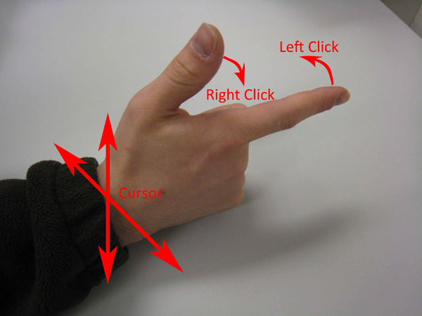
Right hand "finger gun"
In the right hand “downward fist” position, moving the hand upwards scrolls up and moving the hand downwards scrolls down.
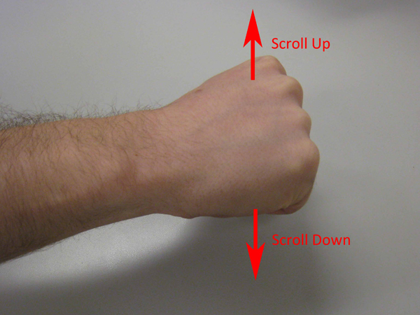
Right hand "downward fist"
In the right hand “upward fist” position, curling the index finger causes an alt key to be typed, while thumbing down causes a ctrl key to be typed.
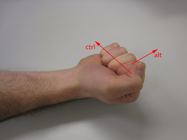
Right hand "upward fist"
Finally, in the right hand “karate chop” position, thumbing down causes a shift key to be typed.
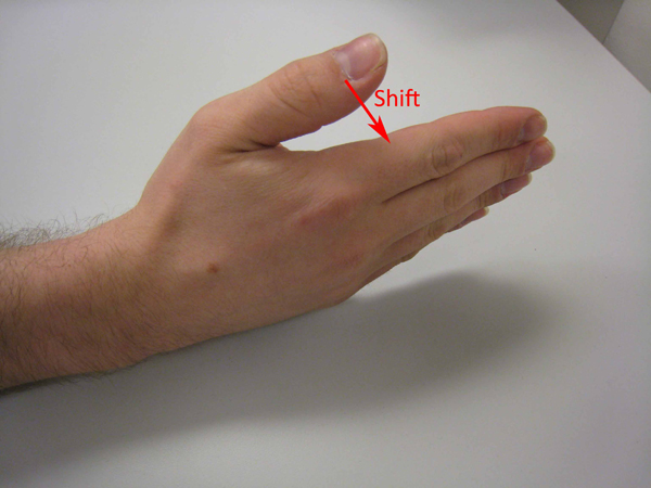
Right hand "karate chop"
Note that the ctrl, shift, and alt motions are meant to be used in combination with the left hand controller.
There are 4 tilt states for the left hand and 14 contact spots on the hands and fingers that can be touched by the thumb, making for a total of 56 keys.
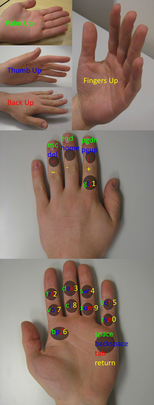
Color-coded left hand key map (contact spots shown as circles)
Audio Feedback:
There is a piezoelectric buzzer on the left hand controller that can play a square wave at various frequencies corresponding to different tilt states. When a contact is activated, audio is played at double the frequency (one octave up).
Note that these frequencies correspond to four of the open strings on a guitar with standard tuning (as well as those of the notes in an E minor 7 chord). The notes are D (293.66 Hz), G (392 Hz), B (493.88 Hz), E (659.26 Hz), for the "back up", "thumb up", "palm up", and "fingers up" positions respectively. It has been brought to our attention, however, that the audio sounds more like it is coming from a bagpipe. The volume can be adjusted via a trimpot on the left hand controller next to the buzzer.
Settings:
We also included calibration/setup hardware. There are four pushbuttons on the left hand controller, each used to reset a different tilt state to the user's preference. To reset the hand position for a tilt state, the button is simply pressed while keeping the left hand in the desired position.
There are two trimpots on the right hand controller for controlling horizontal and vertical mouse sensitivity. There is also a calibration trimpot for controlling how much the index finger must be curled to activate a click. Additionally, the right hand controller includes a big red button for resetting the right hand tilt position (for the “finger gun” gesture) as well as for turning on the entire system and activating the base station.
Logical Structure
Our input system is separated into three basic components. The MCU in the left hand controller takes measurements from a pair of accelerometers to calculate the current tilt position of the hand. Note again that the tilt positions can be reset via pushbuttons. Additionally, it determines which finger or hand contact is currently activated. These readings are then passed over to the MCU in the right hand controller, which is connected by wire. Optionally, the left hand controller can output audio through a piezoelectric buzzer, where the frequency of the audio corresponds to the current tilt of the hand as mentioned above.
Simultaneously, the right hand MCU takes measurements from a pair of accelerometers within a 5 degrees of freedom sensor package, flex sensors, and pushbuttons to determine the current gesture. Next, the right hand MCU processes all readings from both hands them and converts them into the corresponding keyboard or mouse inputs. The requested keyboard and mouse inputs are then wirelessly transmitted to the base station via a packet radio.
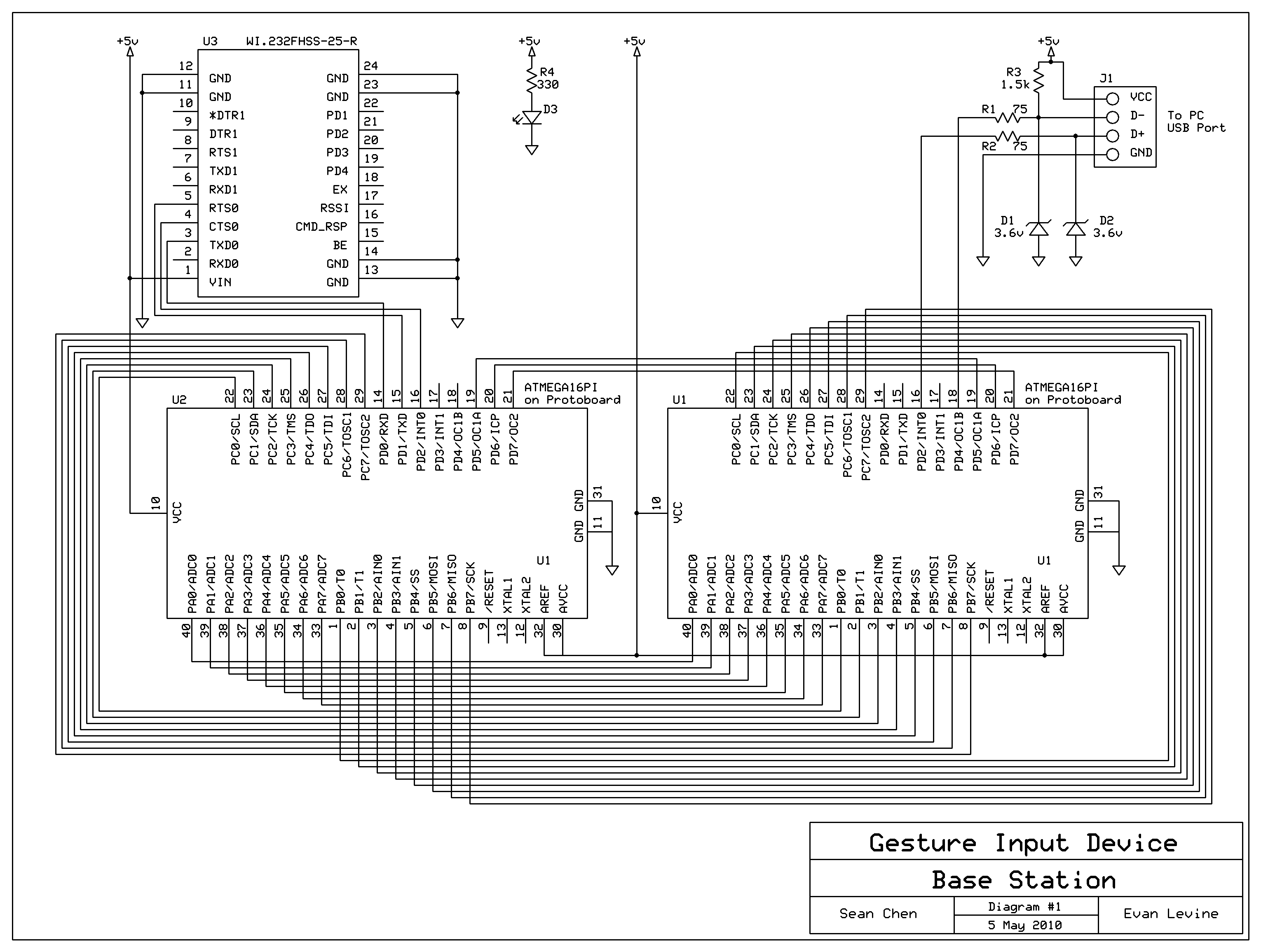
The base station consists of a pair of MCUs. One of them is connected to a second packet radio that receives the incoming data from the hand controllers. This incoming raw data is simply forwarded to the second base station MCU, which runs the software USB program and communicates the requested keyboard/mouse input to the computer through the USB port. The reason we did not use a single MCU to handle both wireless and USB functions is that we found that triggering USART interrupts while operating at high baud rates (57600 bps) interferes with the USB interrupt timing scheme and causes the entire system to be denoted by Windows as an unrecognized device.
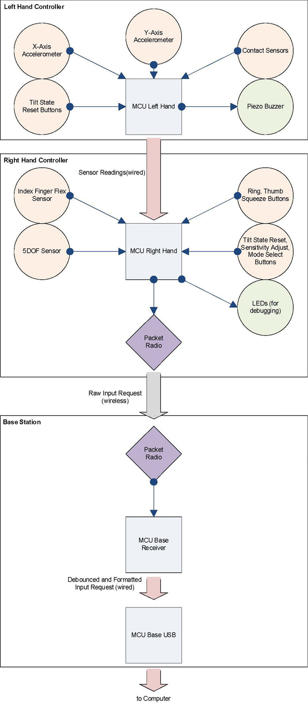
High-level block diagram
Note that the flow is one-way. During the course of the project, we did not find a reason for the computer to need to talk back to Mister Gloves. However, as we will note in our conclusions, our project could be expanded to include the additional feature of allowing the user to reprogram the key mappings of the controllers from a custom program with a simple GUI. This would then require two-way communication.
Hardware/Software Tradeoffs
We decided to implement software USB rather than use a hardware solution such as an FTDI chip since a default software implementation was readily available from the Objective Development V-USB website. This meant we could test it immediately without waiting for a parts order. Another part of this decision was based on the incorrect assumption that we could simply use a single MCU for the base station. As we eventually found out when we attempted to implement wireless communication, high baud rate wireless transmissions to the MCU’s USART are not compatible with USB interrupt timing requirements. By this time in our design process, we had already spent much effort on improving the software USB code and did not desire to switch to using a different interface such as SPI-to-USB. Therefore, we added a second MCU to serve as a receiver to forward incoming raw wireless data over to the MCU running the software USB.
Standards
USB:
The Universal Serial Bus standard allows devices to communicate with a host controller. USB is a common connection method for devices in a number of classes, including storage devices, human interface devices, image capture sources, and audio devices. Our project does not necessarily conform to USB standards, but it has been tested to work with Microsoft Windows XP, Vista, and 7 operating systems. USB is hot-swappable, meaning that devices can be replaced in a running computer without the need to reboot the computer. Our project is indeed hot-swappable. USB provides a data rate of 12 Mbps at full bandwidth, which is sufficient for our application. USB provides a +5V DC line, a ground line, a Data+ line, and a Data- line. When Data+ exceeds 2.8V with a 1.5 kOhm resistor to ground and Data- is less than 0.3V with a 1.5 kOhm resistor to 3.6V, a 1 is transmitted. When Data+ is less than 0.3V and Data- exceeds 2.8V, a 0 is transmitted. We have included these resistors.
A Human Interface Device is, as the name suggests, a computer device which takes input from humans. HID is one of the device classes supported by USB, and our project is an HID. Actions performed by a human are recognized by the device and are sent to the host, and data can go back from the host to the device and then to the human. The device provides the host with an HID Descriptor which tells the host how to read the packets that it will send. We have made sure that we are using the correct HID descriptor and that the host and device successfully communicate using it. Another benefit of our HID is that it requires no additional drivers for basic operation.
FHSS:
Frequency-hopping spread spectrum is a radio transmission scheme which rapidly and pseudo-randomly changes the frequency channel used by the transmitter and receiver. FHSS can reject narrowband interference by spreading the transmission over a wide bandwidth, and channels can be shared without significant interference. Our packet radios do use this scheme in the 902-928 MHz spectrum, and we made sure to switch to a non-default channel on our radios in case another group was using FHSS as well.
Hardware
Left Hand | Right Hand | Base Station | Physical Construction
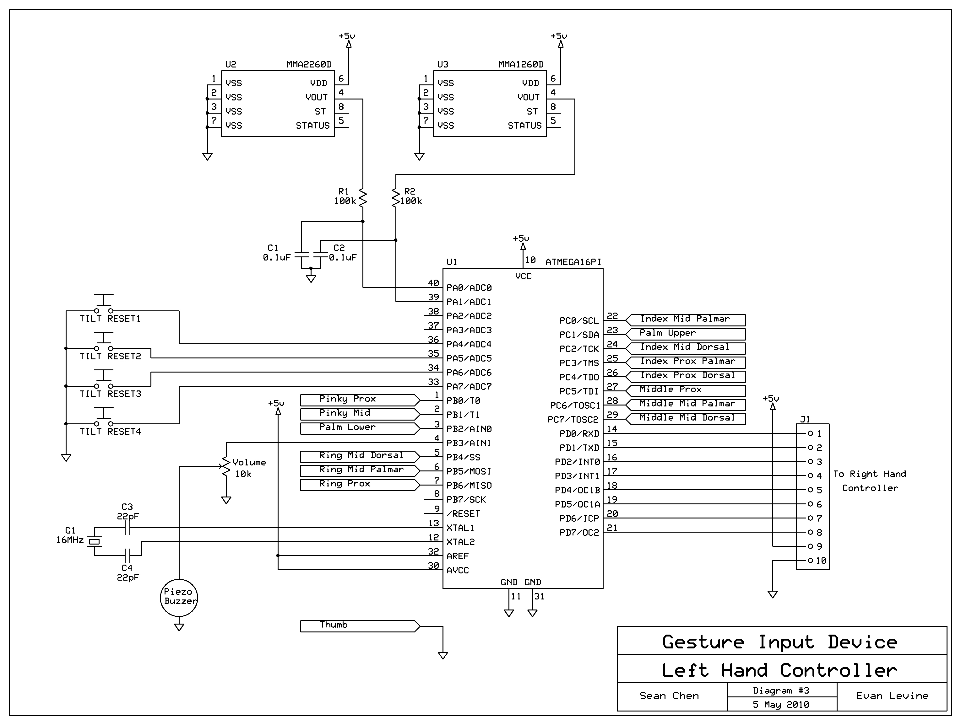
Left Hand Controller
Breadboard and contact sensors mounted on gardening glove sans thumb sleeve
Freescale Semiconductor MMA1260D and MMA2260D Accelerometers:
We used a pair of +/-1.5g single-axis accelerometers after a two-axis accelerometer that we previously used, the Analog Devices ADXL202EB, mysteriously died one night. These were generously donated to the ECE 4760 lab by Freescale Semiconductor. Note that these sensors measure acceleration due to gravity in the Z-axis and X-axis, respectively, and give an analog output. These sensors are aligned such that their acceleration vectors are orthogonal and both lie in the plane of the left hand. Pointing the acceleration vector towards ground results in a higher output voltage and vice versa. We fed the raw outputs of the Z-axis and X-axis sensors through a low pass filter into the ADC pins of the MCU to determine the tilt position of the left hand. We simply used VCC (5V) for AREF on the MCU as well as for VSS on the sensors. This is provided by 4 AAA batteries through a 5V voltage regulator (LM340T5).
We found out that as the supply voltage changes over time due to decaying battery life, the bias points and sensitivities of the accelerometers also vary somewhat. This means that we cannot hardcode the expected sensor outputs for various tilt states and expect them to work over the life of the batteries. Our solution to this was to add four pushbuttons that allow the user to eventually reset the expected sensor outputs for each of the four left hand tilt states as the batteries begin to die.
Z-axis (green breakout) and X-axis (yellow breakout) accelerometers, tilt state reset pushbuttons, buzzer volume trimpot
Contact Sensors:
Our contact sensors are simply a collection of 3M Red Dot electrodes mounted around the fingers and palms and connected to various input pins on the MCU via a soldered wire. The input pins have the internal pull-up resistor activated. We also put a strip of copper around the thumb sleeve and connected it to ground. Then, when a contact sensor is touched by the thumb, the pin receives a logic low value. Otherwise, it is pulled up to logic high. We found that if the thumb does not push firmly on the contact sensors, there is a significant amount of bouncing between logic high and low due to vibrations and uneven metal surfaces. Thus, this requires some software debouncing.
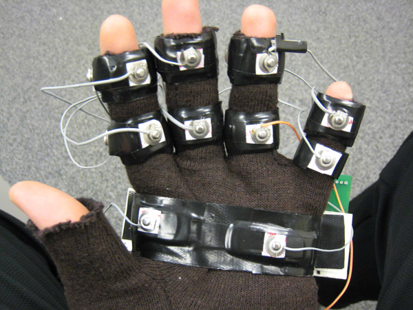
Contact sensors (thumb contact sleeve not shown)
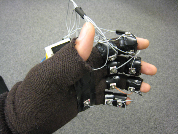
Right Hand Controller
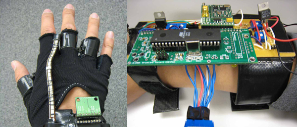
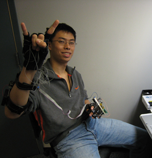
Right hand glove controller and transmitter station (attached to forearm)
Sparkfun IMU 5 Degrees of Freedom Sensor:
Professor Land generously donated us this sensor package. It is actually a breakout board that combines the Analog Devices ADXL330, which is a 3-axis +/- 3g accelerometer, and a 2-axis 500 degree/sec gyro, the InvenSense IDG300. We had originally hoped to use the gyros to control mouse cursor movement since they measure rotational acceleration about an axis, which we thought could lead to more natural cursor motion. However, we found out that the bias point of these sensors drift erratically over the course of only a few minutes and throw off our measurements. Since we did want to make the user have to reset a sensor very often (and definitely did not have time to thoroughly investigate a Kalman filtering implementation), we switched to simply using the accelerometer’s values for the X-axis and Z-axis for controlling the cursor. They are connected to the MCU ADC pins.
The accelerometer is mounted such that the Z-axis runs transverse to the plane of the hand, and rotating the wrist left or right will change its angle towards the direction of gravity. This axis, then, can be used to control horizontal cursor movement. The X-axis lies in the plane of the hand and runs in the direction of the fingers. It changes value when hand tilts up and down. Thus, it is used to control vertical cursor movement.
Note that this is a 3.3V sensor, so we use an appropriate voltage regulator (LD1117V33) to step down from VCC (5V). Additionally, we send 3.3V to AREF on the MCU.
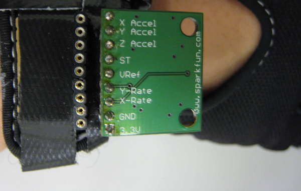
5 degrees of freedom sensor (3-axis accelerometer plus 2-axis gyro)
Spectra Symbol Flex Sensor (FS-L-0112-103-ST):
We bought this sensor from SparkFun and mounted it on the back of the index finger. Note that this sensor increases resistance from approximately 8 kOhms to 12 kOhms when the index finger is curled in. We put this sensor in a resistive voltage divider split across the non-inverting pin of an LM358 op amp. We fed the middle terminal of a trimpot into the inverting pin to allow for calibration. Additionally, we added a 1 MOhm resistor from the op amp output to the non-inverting input to add hysteresis. So, when the index finger is curled in, the voltage at the non-inverting pin rises and the op amp outputs a high signal to the MCU. Flex sensors are very expensive and we decided not to use more than one (well, two originally, but one died due to a late-night soldering accident that destroyed the resistive film). We mounted small push buttons to detect the curling of the thumb and ring finger.
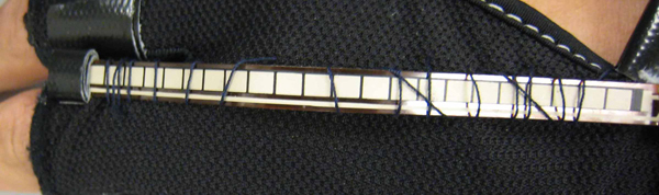
Flex sensor stitched into glove
Radiotronix Transceiver (Wi.232FHSS-25-R):
Radiotronix donated several of these radios to Professor Land, who in turn allowed us to use two of them. We had previously used the Radiotronix RCT-433 and RCR-433 transmitters and receivers, which transmit at a maximum of 2400 bps. This was too slow for sending mouse input requests at a responsive rate. We noticed mouse input lag on the order of hundreds of milliseconds when sending both mouse and keyboard input requests. Therefore, we decided to use these packet radios instead to transmit at the higher rate of 57600 bps in one of several selectable channels in the 902-928 MHz spectrum. This allowed us to transmit our entire block of keyboard and mouse input requests with no noticeable input lag whatsoever. Note that these radios default to having CSMA enabled, which is a collision avoidance scheme that improves transmission throughput at the cost of having higher delay (intended for the case where multiple radios use the same channel). With this enabled, we still get quite a bit of input delay even at 57600 bps. However, since we are using just a pair of radios (where one only transmits and the other only receives), there is no apparent need for activating CSMA. We also did not encounter anybody else using the 902-928 MHz spectrum. Just to be safe, we wrote to the nonvolatile registers within the radio to set a transmission channel other than the default before disabling CSMA.
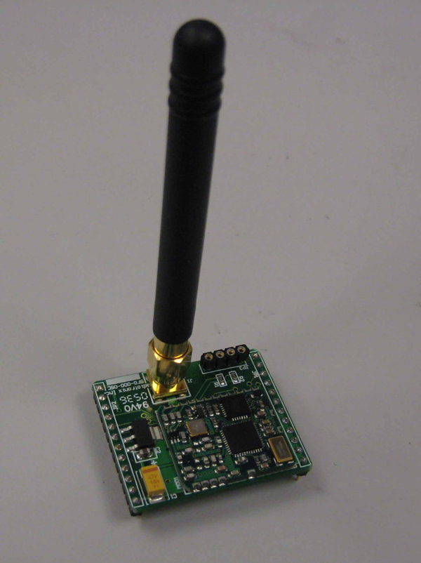
One of two packet radios shown with a helical whip antenna
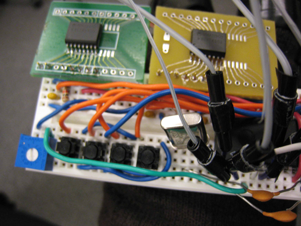
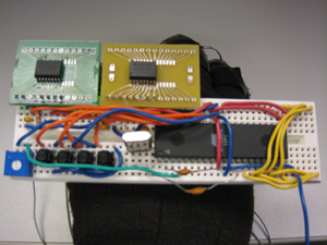
Base Station
The base station consists of a receiver MCU, a software USB MCU, and another Radiotronix packet radio. The receiver MCU has its ports tied to the USB MCU ports so it can forward received data (described in more detail below). We followed the instructions on the Objective Development V-USB website to connect to the USB pins, whereby 3.6V Zener diodes are used to pull the transmitted voltages down to about 3.3V, which lies in the recognized range for the computer’s USB circuitry. Looking at our schematic, 75 Ohm resistors were used to limit current, and a 1.5 kOhm pull-up resistor informs the computer that this USB device falls in the low-speed category.
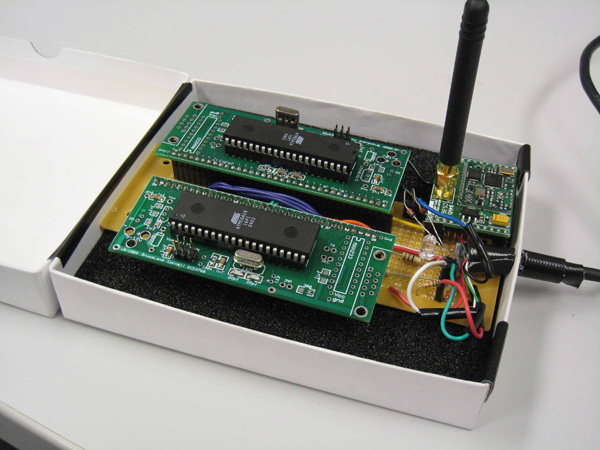
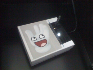
Base station in extremely tight-fitting cardboard enclosure
Physical Construction
The circuitry on the left hand controller was simply put into a small breadboard that we borrowed from the Cornell Computer Systems Lab (this was the smallest breadboard we could find) and mounted on a gardening glove using heavy duty tape. We also covered areas between the contact sensors and the glove with electrical tape to protect the user. We used Velcro, cardboard, and a criminally excessive amount of heavy duty tape to build the forearm harness to hold the circuitry needed for the right hand controller (especially including the large transceiver module). We attached the flex sensors, various pushbuttons, and the 5 degrees of freedom sensor to a weight lifting glove. The entire setup feels slightly bulky, but we once again note that this project is simply a proof of concept, and an actual product would undergo much more miniaturization. Finally, the housing for the base station was put in a small cardboard box with the happy Mister Gloves logo on the top cover.
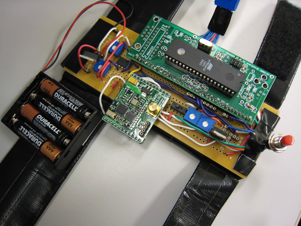
Right forearm harness
Software
Left Hand | Right Hand | Base Station Receiver | Base Station USB
Left Hand MCU
We first calculate some default values for the X-axis and Z-axis accelerometer readings for the four left hand tilt states. These were empirically measured with the voltmeter in lab and are given as definitions in the beginning of the source code. We simply divide, in floating point, the measured voltage value at the output of each sensor for each tilt state by the measured analog reference voltage, and multiply this by 255 before casting the product to an 8-bit value. This would then represent what the ADC normally sees if the sensors are active and the controller is in one of the four valid tilt states.
Next, in the main while loop of the program, we read the tilt state by taking the 8-bit ADC values from each sensor and comparing them to the initially calculated values, allowing for a small margin of error. The user may also push one of four pushbuttons connected to PORTA to reconfigure one of the tilt states to the present hand position. This simply sets the default tilt state value to the current measured value from the ADC.
Finally, we scan through the PORTB and PORTC pins that are connected to the contact sensors to determine which one, if any, is pressed. Note that if more than one sensor is touched, we show that none are activated.
PORTD of the left hand controller outputs to PORTC of the right hand controller. Note that the tilt state is broadcast to the right hand controller through the upper 4 bits of the connection, and the contact state is broadcast through the lower 4 bits.
We also use Timer0 with CTC and toggle PB3 upon compare match, thus creating a square wave output at this pin, which we then tie to the piezo buzzer. To provide some user feedback, we also attempt to play the four frequencies corresponding to the D, G, B, and E strings on a guitar (293.66Hz, 392Hz, 493.88Hz, 659.29Hz respectively), one for each tilt state, as well as the four frequencies an octave above (double the frequency) when a contact is pressed. Measuring the output from the scope, within our range of frequencies, the worst error is no greater than 20 Hz.
Right Hand MCU
Some of the radio transmission code here is borrowed from an example from ScienceProg. The right hand controller MCU begins by waiting for the user to press the big red pushbutton used as a start button. Once this button is pushed, the MCU takes the bias point of the accelerometers, sends the initialization signal to enable the base station MCU, and enters the main while loop. In this loop, the MCU first obtains the tilt state and contact state readings from the left hand controller and obtains the corresponding keyboard key by checking a lookup table. Next, if the ring finger was just squeezed in (activating a push button), we update the tilt state of the right hand controller itself to determine which one of the default starting points for a right hand gesture it is currently in.
If the right hand is in the “finger gun” position, we can then read the X-axis and Z-axis accelerometer values through the ADC to determine cursor movement. We set a lower threshold for this cursor movement to remove cursor movement due to sensor noise. The sensitivity here for horizontal and vertical mouse cursor can be separately adjusted using trimpots. These trimpots output values between the 3.3V analog reference voltage and ground, and the middle terminals are each connected to an ADC input that is read along with the 5 degrees of freedom sensor. Additionally, we use a smoothing function for each axis to generate gradual mouse acceleration, enabling precise (per-pixel) selection with a steady hand and very fast cursor movement as the hand swings wildly:
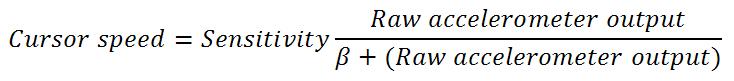
(By raw accelerometer output, we mean the difference between the actual accelerometer output and the voltage bias. We set beta to 55 for best results.)
We next scan the pushbutton under the thumb as well as the flex sensor op amp output to determine clicks. Please note that we do not process simultaneous left and right clicks. The left click always has priority. We also introduce a scheme where upon a left or right click, the cursor is not allowed to move for approximately 393 milliseconds by clearing the horizontal and vertical cursor movement values (this is timed using Timer1). This is intended to aid the user in double-clicking, where the mouse should not be moving between the two clicks. This is implemented simply because curling the index finger or thumbing down tends to move the hand slightly, otherwise causing shaky movement.
If the right hand is in the “downwards fist” position, we do not allow the cursor to move or any left or right clicks to occur. Instead, we set up for a mouse scroll, where if the hand moves upwards, the mouse scrolls upwards, and vice versa. This is detected by the X-axis accelerometer, but the problem here is that the wrist has been rotated to the left by 90 degrees, throwing off the previously computed accelerometer bias. Every time we enter this position from a different one, we immediately reacquire the accelerometer bias. The mouse cursor functions are disabled here.
If the right hand is in the “upwards fist” position, we do not allow the cursor to move either or any clicks to occur. This position is used for sending the ctrl key if the thumb is pushed against the hand, and for sending the alt key if the index finger is curled. Finally, if the right hand is in the “karate chop” position, pushing the thumb back against the hand will send the shift key. Again, the mouse functions are disabled in both cases.
At this point, the right hand controller has determined which keyboard and mouse input requests it needs to send. It now sends 6 bytes:
![]()
Here, ADDR is 0x44 and is checked by the receiver before anything else is read. Note that the 2 most significant bits in the KEYS byte stores the left/right mouse button state. However, if both bits are 1, (since we do not allow both of these mouse buttons to be clicked), the lower order bits in KEYS actually stores the mouse scroll wheel setting. Only the most significant 3 bits of MODIFIERS are used (for the ctrl, shift, alt keys).
There is a game mode switch on the right hand controller, which disables the mouse cursor freezing feature and allows arrow keys to be sent (at the d, c, v, and x key contact spots regardless of tilt), which enables games such as first person shooters to be more easily played.
Base Station Receiver MCU
Again, some of the receiver code here is borrowed from an example from ScienceProg. The code here runs an ISR whenever a sync byte is received from the UART (connected to the packet radio), and then proceeds to grab the address, keys/mouse buttons, mouse horizontal, mouse vertical, and modifier keys bytes. If the address matches, then PORTA, PORTB, PORTC, and the three upper bits of PORTD are updated with the updated values to send to the USB MCU. Note that PORTA contains the raw keys/mouse buttons data, PORTB contains the mouse horizontal data, PORTC contains the mouse vertical data, and the 3 upper bits of PORTD contain the ctrl, shift, and alt key data.
One caveat here is that if the entire base station is simply plugged into the USB port of the computer, the computer actually starts to spit out junk keys and mouse movements until the right hand controller starts transmitting desired input requests. We are not sure why exactly this happens. However, as hinted above, we did fix this by disabling the USB MCU until the right hand controller is turned on and transmits an initialization signal (when the big red pushbutton on the harness is pressed). This works by making PD7 an enable pin for the USB MCU. If this pin is low (its default value upon initialization), then the USB MCU is disabled from sending anything to the computer’s USB port. However, once this initialization signal is sent from the right hand controller, PD7 on the receiver MCU goes high and the USB MCU is now enabled. Afterwards, PD7 is used as one of the bits for sending modifier keys (in an active-low setup). Note that the base station cannot be disabled again after enabling it unless it is disconnected and reconnected.
Base Station USB MCU
The code here is borrowed from the Objective Development V-USB website. We took a minimal example of a combination keyboard/mouse HID device and modified it to send to the computer the keyboard and mouse input buffers taken from the raw data presented by the receiver MCU. Notice that in the keyboard case, the value taken from PORTA of the receiver MCU actually indexes a lookup table within the USB MCU to pluck out the correct HID report value for the corresponding key.
We run a debouncing scheme here where a key from the same contact cannot be sent to the computer more than once every 262 milliseconds using a Timer1 compare ISR. This is required since the contact sensors are extremely bouncy. Additionally, this prevents a string of unwanted keys to be entered if a contact sensor happens to be activated if the left hand is repeatedly transitioning back and forth between two valid tilt states. Note that, however, for backspace and spacebar, we reduce this time to 131 milliseconds to allow for faster text revision. Additionally, if arrow keys are being sent in the case where game mode is activated, they are not debounced at all.
Results
Our input system, while somewhat bulky, is extremely easy to use once it is worn. The right hand mouse controller is precise enough to highlight specific text as well as click on the small buttons in the taskbar. With a steady hand, the cursor can be moved a single pixel at a time. The slight delay added after the mouse button clicks assists successfully in double-clicking operations.
Switching between different gestures on the right hand controller is also seamless. For example, the right hand can quickly traverse from controlling the mouse cursor to controlling mouse scrolling.
The left hand keyboard controller does not have any trouble switching between different hand tilt positions. Additionally, the contact sensors are reliable and the debouncing within the USB MCU successfully prevents unwanted keys to be entered.
We also successfully tested our system playing the game Portal on the PC. The controls were quite responsive and made for a novel and intuitive game experience.
Here is a video demonstration:
The wireless and USB aspects of the project are invisible to the end user in that they do not present any complication to using the input system, but rather, convenience, due to the untethered, hot-swappable, driverless setup. Windows is always able to recognize Mister Gloves as a HID. Running our final code, we have never logged any occurrence of an unrecognized device message. The wireless system does not produce any noticeable input lag and does not appear to interfere with any other of the designs encountered in the ECE 4760 lab or elsewhere on campus.
We also enforced safety by adding an additional layer of electrical tape for insulation between any metal contacts and the glove itself, therefore limiting the chance of human flesh getting into contact with the circuit.
Conclusions
Analyze your design in terms of how the results met your expectations. What might you do differently next time?
The project was challenging because it forced us to think about a large system while debugging. One goal in the proposal that we did not reach was to implement programmable gesture combinations. We could have allowed users to perform gestures and tie them to keys or shortcuts on the computer. This would have required us to write host software which could communicate with our system. Additionally, the packet radios would need to communicate both ways. Implementing that functionality would have been extremely time-consuming, so we decided to re-prioritize and include other features that were not included in our proposal, such as mouse scrolling and audio feedback.
Our project is a proof of concept. We could have spent more time on the actual construction or perhaps design small PCBs to make our input system prettier. In fact, we surmise that each of the circuits for the two glove controllers could be miniaturized to fit in enclosures not larger than an Altoids container. The interconnects could be woven into the glove using conductive thread, and the base station could be shrunk into the size of a USB key. These would be some of the next steps to take should we choose to further pursue our concept.
How did your design conform to the applicable standards?
Our design does not necessarily conform to wireless or USB standards, but the system has worked without problems on Microsoft Windows XP, Vista, and 7 operating systems.
Did you use code in the public domain?
Yes, V-USB, from Objective Development, is published under the GNU General Public License Versions 2 and 3.
Did you have to sign non-disclosure to get a sample part?
No.
Are there patent opportunities for your project?
The V-USB code is not patentable because it is licensed in the public domain, and the wireless modules do not comply with FCC regulations. Although we have not seen commercial hand gesture-based computer input devices exactly like ours, the Peregrine and Clove systems are based on similar concepts. Obtaining a patent would at least entail an overhaul of the USB interface (possibly using a hardware chip) and further improvements to the input feature set.
Are there publishing opportunities for your project?
No, we do not believe that there are publishing opportunities for our project.
Did you reuse code or someone else's design?
Yes, we reused the V-USB code and hardware schematic for our USB chip. We also borrowed transmission and receiver code from ScienceProg. The rest of our code was original.
Are you reverse-engineering a design? How did you deal with patent/trademark issues.
No, we are not reverse-engineering a design.
Ethical considerations. Referring to the IEEE Code of Ethics, specifically explain how decisions you made or actions you took in this project were consistent with this Code of Ethics.
In designing and building our project, we adhered to the IEEE Code of Ethics. We were careful to ensure that our system was safe to use under battery power. If the leads from the quad AAA battery source were to come in contact with the skin, the exposure to electric current would not be harmful. To further prevent this possibility, we used insulating tape on the glove to prevent contact between the skin and any electronics. None of the materials that we used can cause physical injury. We have invested a great deal of time into testing our system, and we are confident that there are no shorts which might cause any of the chips to burn. We truly appreciate criticism of our project and we have used several suggestions and criticisms to make improvements to our design. We have conducted ourselves in a safe manner in the lab using soldering equipment, power supplies, cutting tools, and any other equipment which must be safely operated. We have treated our peers kindly and fairly without viewing the final project period as a competition, and we have helped other groups by giving constructive comments on their projects. By posting our project on the web, we will demonstrate a proof of concept that could be useful for developers of other human interface devices, and we encourage those developers to draw from our concept. We have benefited from the material available on the final project page, and we are happy to make a contribution ourselves. We have made sure to give the appropriate accreditations to V-USB for providing the USB driver that we modified, as well as to ScienceProg.
Legal considerations. For instance, if you use a transmitter, you must discuss the appropriate FCC legal restrictions.
The transmitters that we are using do not comply with FCC regulations. Operation in the 890-940 MHz range is restricted to devices which use RF to measure the properties of materials, and our project is not such a device. Another requirement is that the antenna not be replaceable by the user, but both of our antenna jacks are exposed and can be removed and replaced by anyone using Mister Gloves.
Appendix
Code Listing | Schematics | Parts List | Division of Labor | References
Code Listing
Right hand controller MCU: righty.c
Left hand controller MCU: lefty.c
Base station receiver MCU: receiver.c
Base station USB MCU: usb_main.c
(The rest of the USB code can be downloaded from the HIDKeys example at Objective Development.)
Schematics
Right hand controller:

Left hand controller:
Base station:
Parts List
| Component | Part Number | Qty | Cost | Acquire Method |
|---|---|---|---|---|
| ECE 4760 prototype board | -- | 3 | $12.00 | Lab stock |
| Spectra Symbol Flex sensor | FS-L-0112-103-ST | 1 | $12.95 | Purchased |
| Solder board | -- | 2 | $5.00 | Lab Stock |
| Duracell AAA Batteries | -- | 4 | $3.00 | Purchased |
| Machine/header pins | -- | 350 (est.) | $17.50 | Lab stock |
| Velcro tape | -- | 1 | $3.00 | Purchased |
| ST Microelectronics 3.3V Voltage regulator | LD1117V33 | 1 | $1.95 | Purchased |
| Sparkfun 5 degrees of freedom sensor | -- | 1 | 0 | Donated by Prof. Land |
| Nike Weightlifting glove | -- | 1 | 0 | Pre-owned |
| Gardening glove | -- | 1 | 0 | Pre-owned |
| Atmel ATmega16 Microcontroller | ATMEGA16 | 4 | 0 | Lab stock |
| Mini protoboard | -- | 1 | 0 | Borrowed from CSL Lab |
| Freescale Single-axis accelerometers | MMA2260D, MMA1260D | 1 of each | 0 | Lab stock |
| Radiotronix Transceiver | WI.232FHSS-25-R | 2 | 0 | Donated by Prof. Land |
| USB Cable | -- | 1 | 0 | Salvaged |
| Resistors, trimpots, capacitors | -- | -- | 0 | Lab Stock |
| National Semiconductor 5V Voltage regulator | LM340T5 | 1 | 0 | Lab Stock |
| 3.6V Zener diode | -- | 2 | 0 | Pre-owned |
| National Semiconductor Op Amp | LM358 | 1 | 0 | Lab Stock |
| Pushbutton | -- | 7 | 0 | Lab stock |
| LED | -- | 4 | 0 | Lab stock |
| Battery case | -- | 1 | 0 | Lab stock |
| Microcontroller ribbon cable | -- | 1 | 0 | Lab stock |
Total: $55.40
Division of Labor
Hardware:
Logical structure - Sean
Circuit design - Sean and Evan
Soldering custom PCBs, breakout boards – Sean and Evan
Construction of
controllers, base station - Sean and Evan
Construction of harness - Sean
Debugging accelerometers, flex sensors – Sean and Evan
Testing and building contact sensors
- Evan
Programming/configuring packet radios – Sean and Evan
Software:
Right glove controller MCU code – Sean and Evan
Left glove controller MCU code – Sean
Receiver MCU code – Sean
USB MCU code – Sean
Miscellaneous:
Ordering parts/samples - Sean and Evan
Report/web page - Sean and Evan
Budgeting - Evan
Schematics - Sean
Photography and other diagrams - Sean and Evan
References
Datasheets:
ATmega16
ADXL330 Accelerometer
IDG300 Gyro
FS-L-0112-103-ST Flex Sensor
MMA1260D Accelerometer
MMA2260D Accelerometer
Wi.232FHSS-25-R Packet Radio
Vendor Sites:
Digikey
Sparkfun
Code/designs borrowed from others:
V-USB
ScienceProg
Acknowledgements
We thank the following people and groups for helping us to design and build our project:
Objective Development for the software USB implementation.
ScienceProg for the transmitter/receiver code.
Radiotronix and Professor Land for donating two transceivers.
Freescale Semiconductor for donating two of the accelerometers.
Cornell Computer Systems Lab for allowing us to borrow a mini breadboard.
Professor Land for teaching us how to design with microcontrollers and how to debug many aspects of our project, as well as for donating the 5 degrees of freedom sensor package.
The ECE 4760 TAs for helping us troubleshoot problems and keeping the lab open into the wee hours of the morning.

Mister Gloves!
Mister Sean!
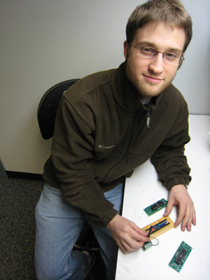
Mister Evan!
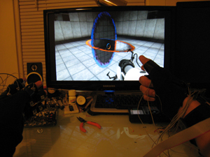
Playing Portal with Mister Gloves
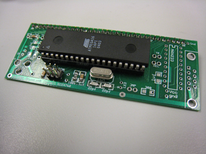
ATmega16 on custom prototype board
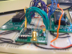
Base station prototype
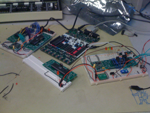
Breadboard party
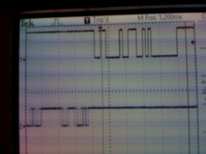
Packet radio reception scope trace
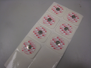
3M Red Dots used for contact sensors
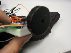
Piezoelectric buzzer (bagpipe imitator)
Circuit on left hand controller
Base station in mood lighting