Weiqing Li (wl336) and Boyi Ma (bm337)
Introduction
In short, our project is just an isolated floating plate. Just as our title explained, it is mainly a floating plate that is segregated from all outside vibration using electromagnetic force.
This purpose of the project is to design a system that complements common passive shock absorption mechanics and enhances their performance.
The main idea of the project is that if we can provide instant support for any load putting on a plate and maintain a constant supporting force when the system reach balance, we can isolate all the background mechanical vibration. To achieve the best result, we choose a hybrid of electromagnets and permanent neodymium magnets to provide supporting force and use PID feedback loop to control the system so we can reduce the power consumption of the system.
High Level design
Rationale
As we can see, there are many situations that requires absolute vibration free environment, for example, Electron Scan Microscope. Traditional passive shock-absorption systems take a large amount of space and needs very expensive equipments. So we want to provide a small, inexpensive solution for those occasions. Furthermore, active anti-shock system has a better performance than the traditional passive anti-shock system because electromagnets can let the system go back to its balanced position faster than normal springs can do.
Background Math
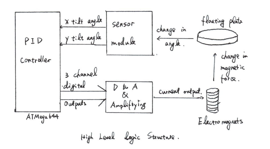
The key algorithm for this project is the PID feedback loop. The PID loop controls the magnetic strength of the three electromagnets using the feedback from the two horizontal sensors.
PID controller
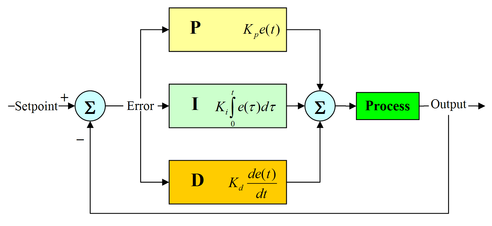
A proportional¨Cintegral¨Cderivative controller (PID controller) is a generic control loop feedback mechanism widely used in industrial control systems. Generally speaking, a PID controller calculates the "error" value as the difference between a measured process variable and a desired value. The controller attempts to minimize the error by adjusting the control inputs. In the absence of an explicit function between the inputs and the outputs, PID controllers are the best controllers.
The PID controller calculation involves three separate parameters: the proportional, the integral and derivative values, denoted P, I, and D. The proportional value determines the reaction to the current error, the integral value determines the reaction based on the sum of recent errors, and the derivative value determines the reaction based on the rate at which the error has been changing.
By tuning the three constants in the PID controller, the controller can provide control action designed for specific process requirements. The response of the controller can be described in terms of the responsiveness of the controller to an error, the degree to which the controller overshoots the set point and the degree of system oscillation.
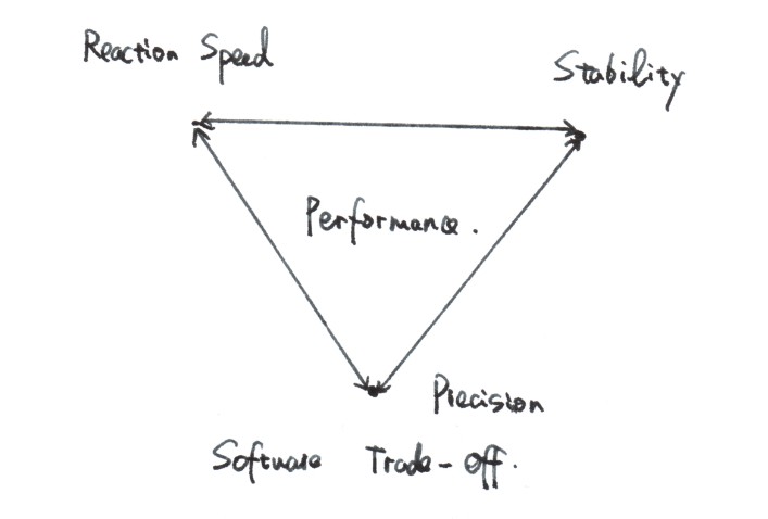
High Level Logic Structure
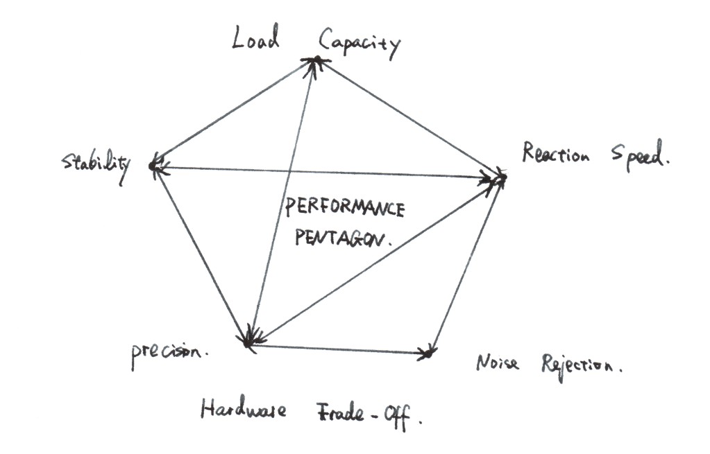
Hardware/Software tradeoffs
Standards and Patents Involved
We did a Google search using key word ˇ°electromagnetic levitation balancing active anti-shock PIDˇ± and found that there are not many articles on our topic.
Although Lorenz Levitation is an active research area, there does not seem to be any standard and patents on it.
In addition, we are using a DC electromagnet so there is no problem with RF standard and we did not find any standard on static magnetic field.
Hardware Design
Mechanical Parts
Self made platform
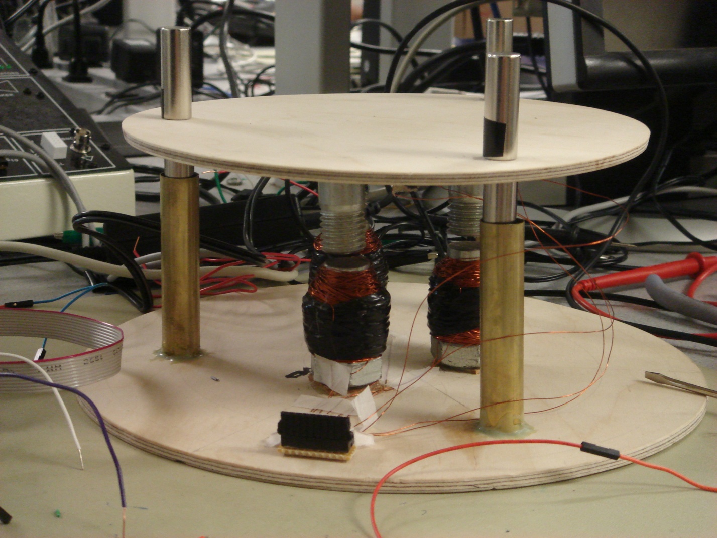
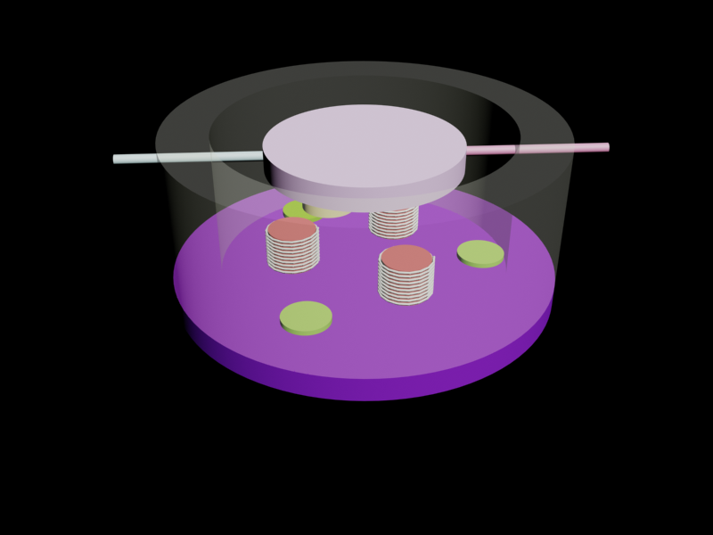
We carved two circle plates and cut three equal length brass tubes. The larger plate is used as the base and the small plate is used as the floating plate. The brass tubes are cut into appropriate length to prevent the floating plate from moving horizontally freely. Three pairs of 0.5ˇŻ diameter and 1.5ˇŻ length neodymium magnets are put into the brass tubes. Three of the magnets are glued on the base in a equilateral triangle way and the other three are glued on the floating plate on the corresponding positions. And we use the pushing force between them to complement the gravity of the floating plate. Three electromagnets are glued on the base in a reversed equilateral triangle way and the electromagnets are 60% closer to the center of the base than the magnets and three iron rods are placed on the floating plate on the corresponding positions. The base adjusts the floating height and the inclination angle of the floating plate by controlling the pulling forces of the three electromagnets. The reason why we place the electromagnets closer to the center of the base is from experiment we found even a huge amount of power (as high as 30 Watts for each electromagnet), the magnetic forces of the electromagnets are still much smaller than the powerful neodymium magnets. So if we make the distances between the electromagnet and the iron rod equal to the distance between the two pushing neodymium magnets at their balanced position, the pulling force between the electromagnet and the iron rod will be very weak and not effective enough. So we need to make the distance between the electromagnet and the iron rod nearer. However, this will make the inclination angle range of the floating plate smaller because the electromagnet and iron rod will hit each other at large inclination angle. To solve this problem, we move the electromagnets closer to the center and in this way the inclination angle range increases due to the lever effect. From experiments we also noticed that the magnetic force between two magnetic materials increases sharply as the distance between them decreases. So the magnetic force between the electromagnet and the iron rod is still strong enough to control the floating plateˇŻs position, even if they are placed close to the center of the base. The model picture below is drawn using 3ds max.
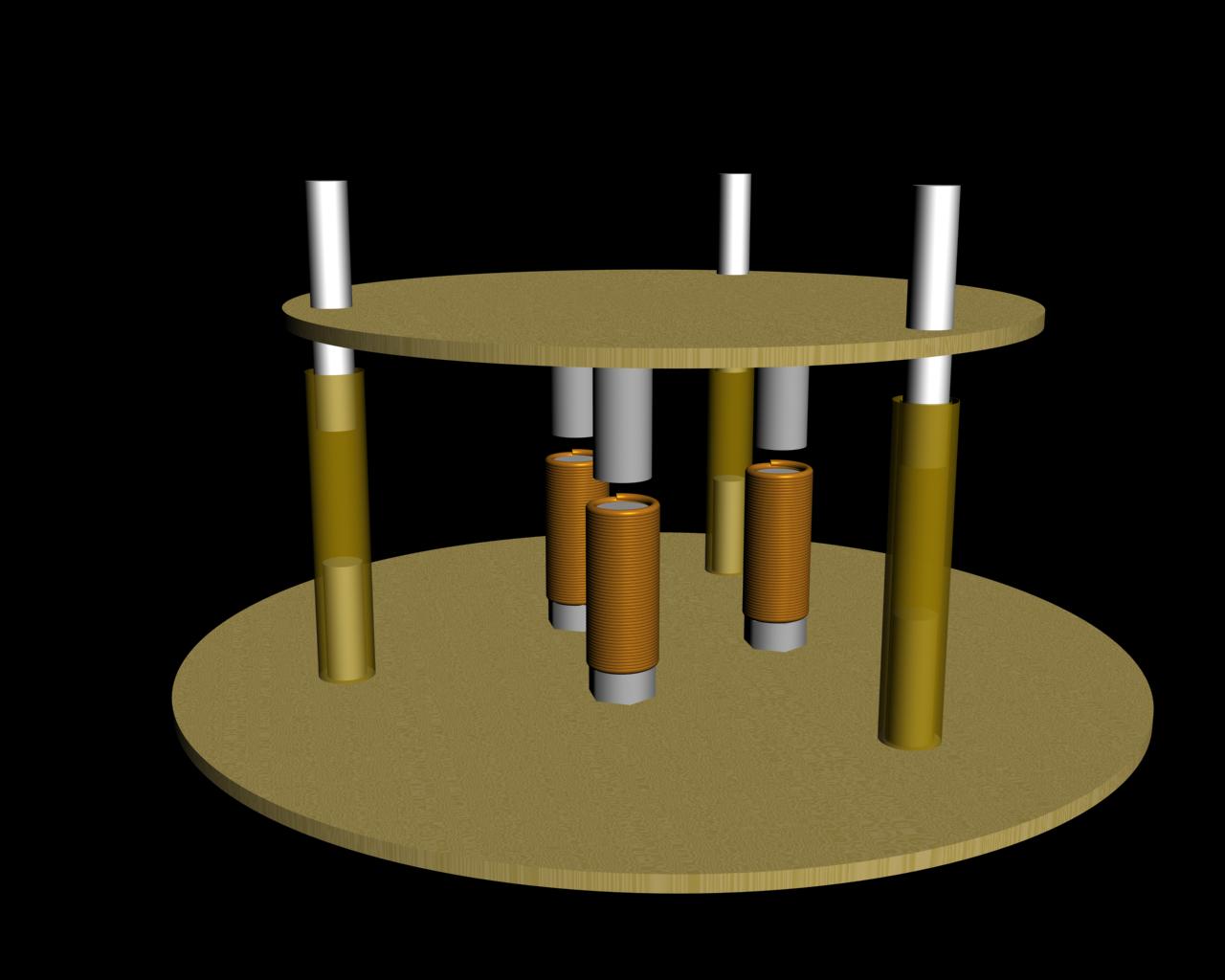
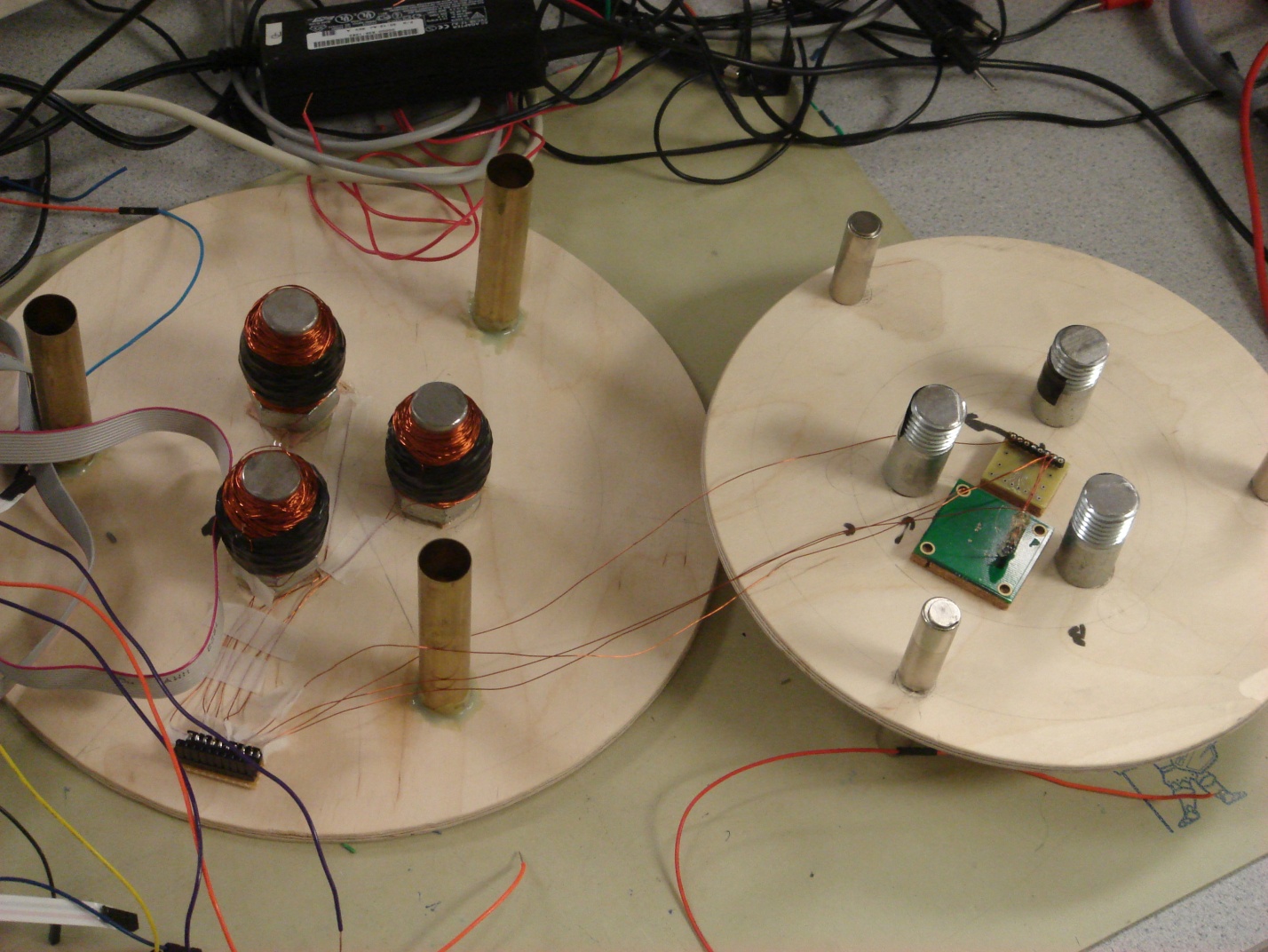
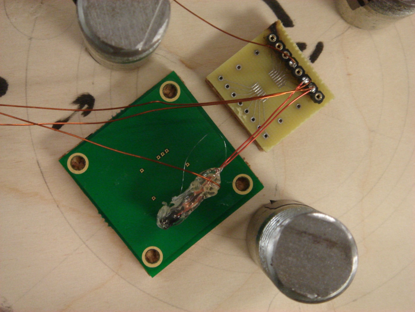
And the real base:
Electrical Parts
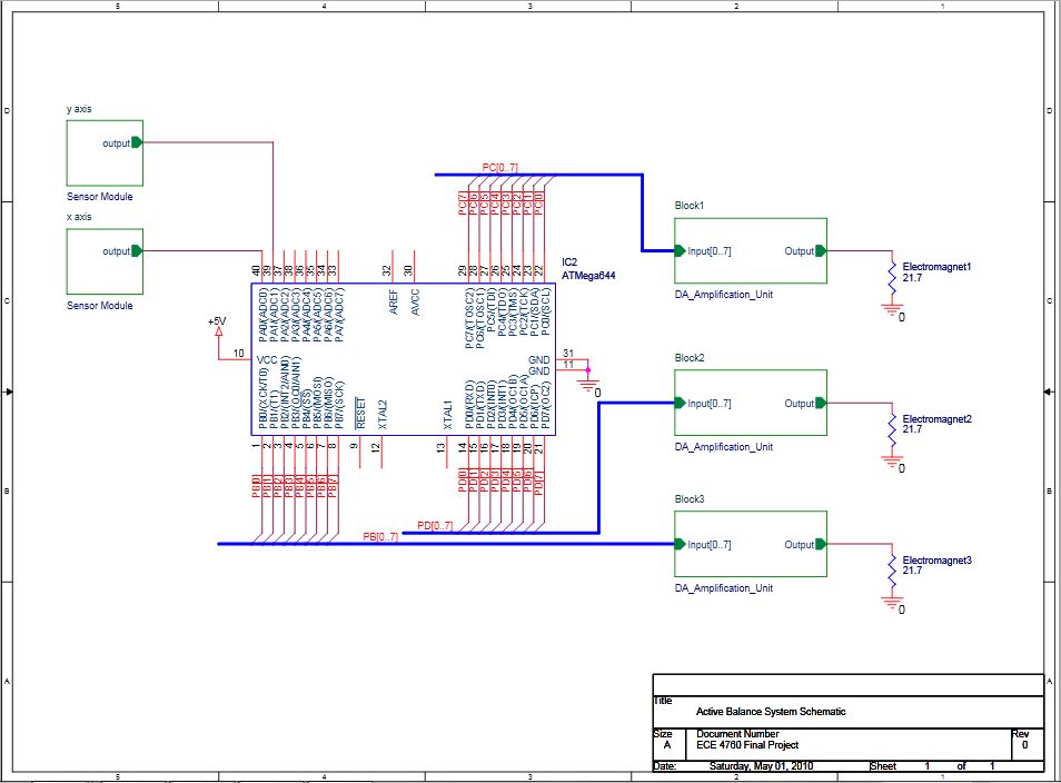
High Level Schematic
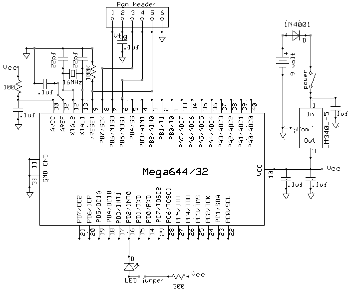
Custom PC Board for Mega644
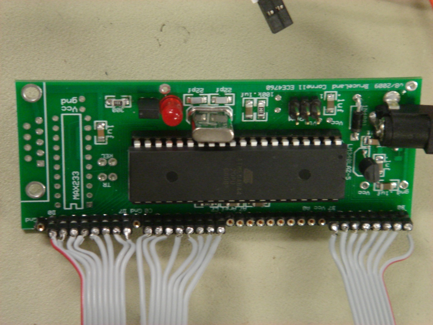
To interface the ATMega644 with our circuitry, a custom PCB is used.
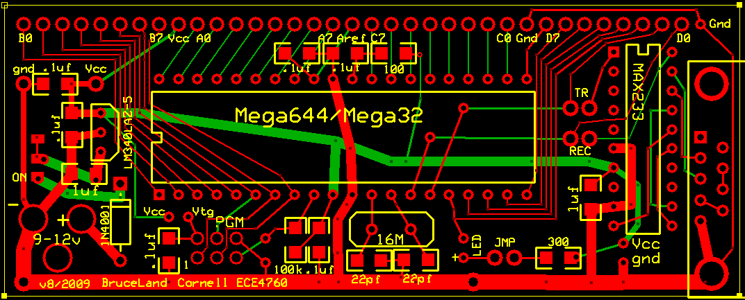
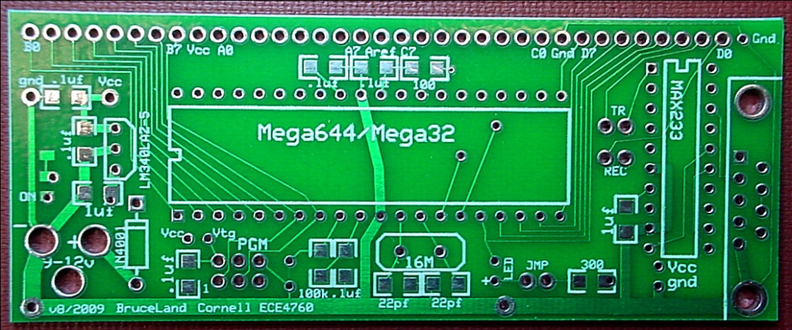
The PC board mainly provides the power supply and serial interface for the ATMega644/32. It uses a LM340LAZ-5.0 power regulator to provide 5V power for ATMega644. The 16MHz Crystal provides external clock reference. The board also gives programming header (PGM) and an LED connected between pin D.2 and ground for debugging. The connection we used is as follows.
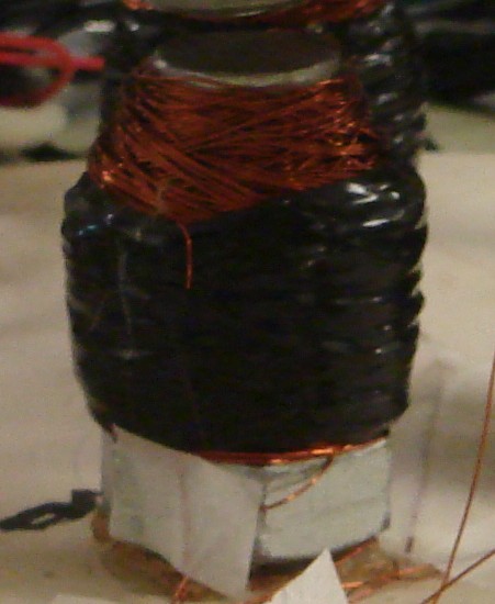
Self made 21.5 Ohms electro magnets
At first we tried to use the neodymium magnets as the cores of the electromagnets because neodymium has very high magnetic permeability but from experiment we found the electromagnets are too weak to conquer the neodymium magnets. So we cut several 3/4ˇŻ diameter bolts into iron rods and use them as the cores of the electromagnets. Also, due to the power supply limit, we need to make the electromagnets has high voltage and passes low current to achieve high power. From experiment, we found the appropriate maximum power for the electromagnets are about 30 Watts each. We use #28 magnetic wire to build the coils and the maximum current #28 wire can pass is 1.4 amps. In this case, finally we decided the resistance of the coils to be 21.5 ohms each and the maximum voltage we can add between its two ends is about 25 Volts. It really took us some time to build the coils because the resistance of #28 wire is about 0.212 ohm/meter so we need 100 meters of wire for EACH coil! In this we can build strong electromagnets and avoid burning the coils. Even the maximum current through the coil is only 1.2 amps, the coils will still become hot after some time. For good heat dissipation, we add three heat sinks for each electromagnets and high-performance Arctic Silver-TM 5 thermal grease is used for good contact between the iron cores and the heat sinks. We cascade three 12V 2.5A power supplies into one for an electromagnet.
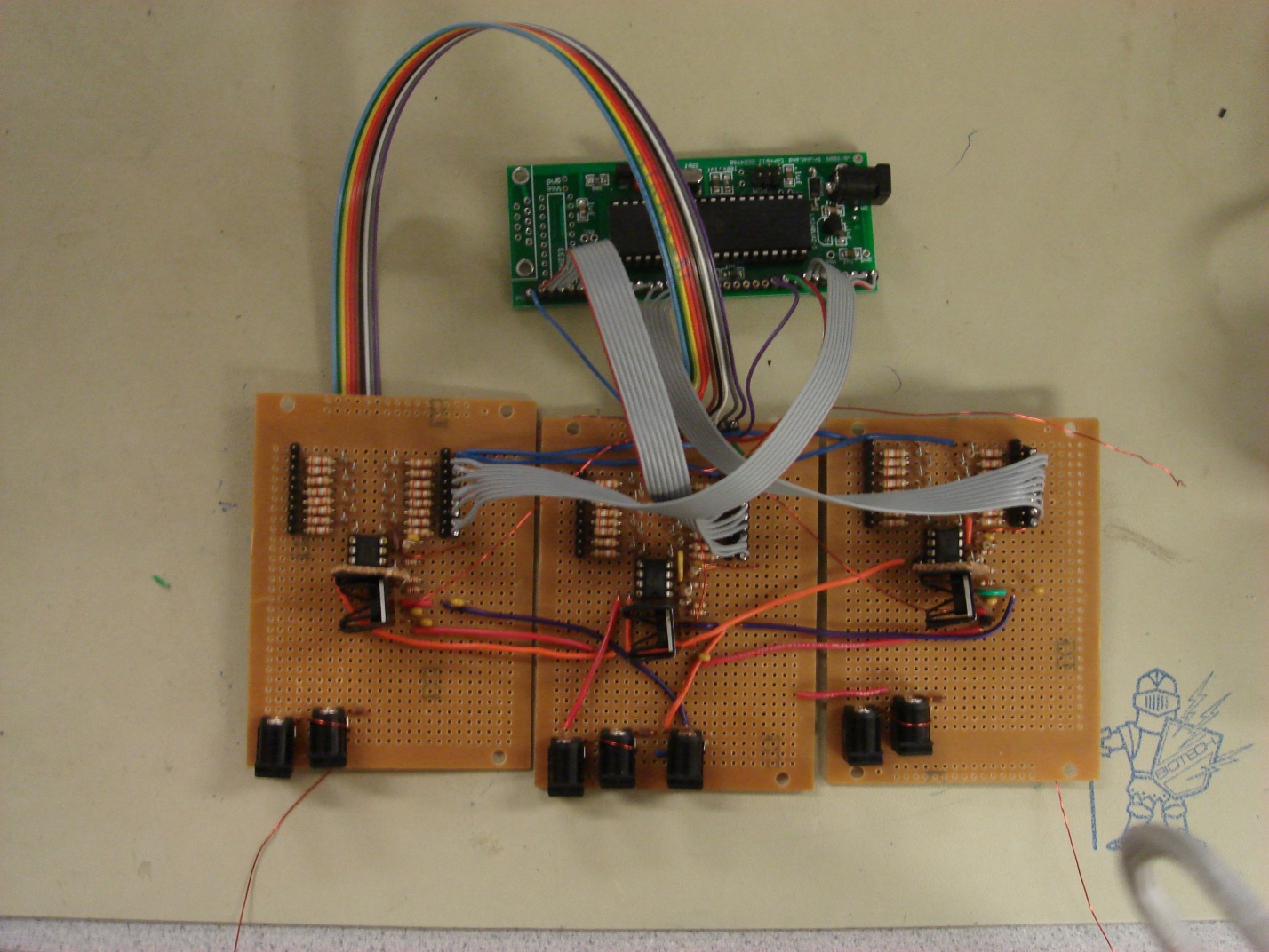
DA converter and Amplifying Module
The DA converter and Amplifying Module takes digital input from the MCU and converts it into analog voltage and supply it to the electromagnets.
The module includes three stages: the DAC stage, the pre-amplifying stage and the power amplifying stage.
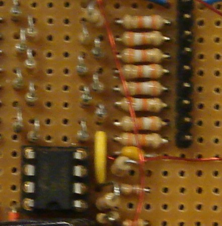
The DAC stage uses a ladder network to convert the digital input to analog voltage. The pre-amplifying stage uses LM358 to serve as a buffer stage to provide low output impedance. Finally, the power amplifying stage amplifies the voltage and provides large current to electromagnet. The schematic is shown as follows. The specific part will be discussed later
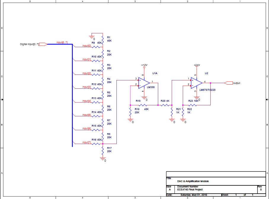
R-2R 8-bit ladder network with Buffer Stage
To achieve enough accuracy, we use three eight-bit DACs for electromagnet strength control. We use Port B, Port C and Port D to control the three electromagnets separately. We use the DAC to output small analog voltages and use LM358 op-amp to amplify the signal. The DAC is built using the ladder network scheme as described in the above figure. All of the resistors are matched within 0.3% discrepancy to achieve enough precision. After the ladder network, we use a non-inverting amplifier to amplify the small circuit in order to drive the power transistor.
We need![]() in order to balance out the variation caused by the small current injected into the op-amp. In this case, we use
in order to balance out the variation caused by the small current injected into the op-amp. In this case, we use![]() and
and ![]() . However, the gain of this non-inverting amplifier becomes
. However, the gain of this non-inverting amplifier becomes![]() so the maximum output can be as high as 15V. To meet the gain requirement of the power transistor, we need to make the maximum voltage to be below 2.2V. So we connect a
so the maximum output can be as high as 15V. To meet the gain requirement of the power transistor, we need to make the maximum voltage to be below 2.2V. So we connect a ![]() resistor in series with a
resistor in series with a ![]() resistor to create a voltage divider. And this will linearly decrease the output voltage.
resistor to create a voltage divider. And this will linearly decrease the output voltage.
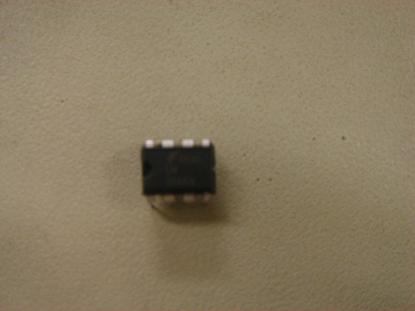
LM358 Operational Amplifier
LME49720HA is used to amplifier small signals from the sensor and for the R-2R DAC. This Op-amp has very high slew rate, Sound-to-noise (SNR) ratio and over 100dB of large DC voltage gain. Its input offset voltage is very low and its noise is only ![]() . For this project we use 3 LM358 op-amps and we get the free in the lab.
. For this project we use 3 LM358 op-amps and we get the free in the lab.
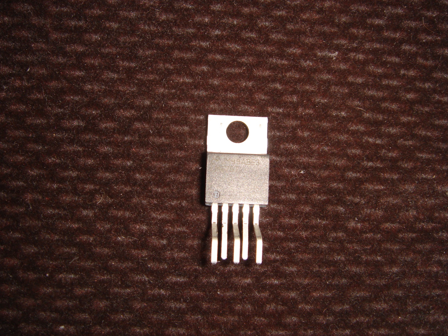
LME675 High Output Current Operational Amplifier
LME675 is used to drive the electromagnets since we need to put a maximum of 1.2 amps through it at a voltage of 22 volts. However, this op-amp requires a open-loop gain of at least 10 to stabilize. So we make our control voltage between 0V and 2.2V.
Sensor Module
The tilt sensor module consists of an accelerometer and a voltage shifter to determine the tilt angle of the floating platform. The accelerometer outputs linear voltage with respect of acceleration. The level shifter is implemented because we did not use the full range of the accelerometer so we need to shift the voltage to get a more accurate result. The schematic is as follows. Specific parts will be explained later.
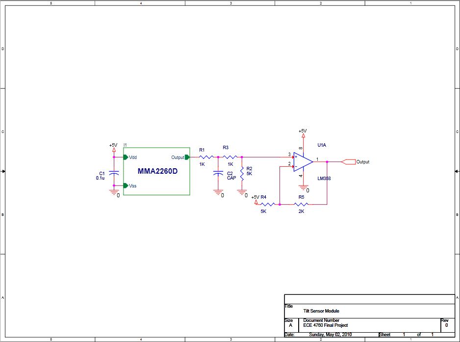
MMA2260D X-Axis Accelerometer?
For keeping the floating plate horizontal we need horizontal sensors. Low-g accelerometers may be used as horizontal sensors. To save our budget, we use two X-axis accelerometers and keep them perpendicular to each other instead of use one XY-dual-axis accelerometers because they are free. MMA2260DˇŻs output voltage is approximately ?when it is kept horizontal and has can measure a maximum acceleration of about 1.5g so it is a very good choice to be used as our horizontal sensor. To keep the chipˇŻs surface flat, we stick wooden papers on the PCB around the chip.
Software Design
Why using DAC instead of PWM
PWM is easier to implement and requires way less hardware. We can control the duty cycle of the PWM to adjust the average output voltage. However, it will introduce more noise to our system because the output is not a constant analog voltage. So our output is simply digital values from 0 to 255.
void ADconvert(void):
This function completes the task of finishing two AD conversion in every program cycle. We set the result to be right adjusted so we have 10-bit precision. First we set the input of ADC to be ADC0, which is connected to the x-horizontal sensor. Then we start a conversion and get the x-horizontal sensor value. After that we set the input of ADC to be ADC1, which is connected to the y-horizontal sensor. And we start another conversion and get the y-horizontal sensor value. This is what this function does.
void get_error(void):
This function gets the error, which is proportional to the inclination angle. First we run the function ADconvert once. Because our result is 10-bit, from experiments we found the converted digital value we get when the horizontal sensor is kept flat is 512. Because we always want to keep the floating plate horizontal, at the beginning of the program we define the target x and y value to be both 512. So this function simply calculates the difference between the values we get from ADconvert() and our target values. Finally the errors are stored in two variables: error_x and error_y.
TIMER 0 interrupt
In Timer 0 interrupt, we assign the values we calculated in the main program to Port B, C and D and this will make the update time equal for each calculation. The good point for this is the system becomes easier to control.
Since most of the high frequency noise will not even pass through due to the inertia of the heavy floating plate. We set TIMER0 interrupt to overflow interrupt. 16M/256= 62.6KHz.
void PID(void):
This is the core section of our software part. The PID control is really complicated because we need to actively adjust all three magnets in order to balance the whole floating plate. We divide the PID control into two parts: X-balancing and Y-balancing. Our horizontal sensors are placed as follows.
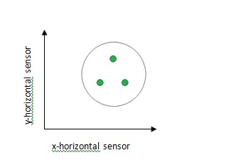
In the above graph, the green circles are electromagnets. In our scheme, in every program cycle we read the inclination angles from the two accelerometers. Then we compare the two values, x-error and y-error, which is proportional to the inclination angles of the board in x and y directions. If x-error is larger than y-error, we need to do x-direction PID adjustment at this cycle and vice versa.
LetˇŻs first consider about balancing in x direction:
We use the traditional PID method, so we first need to calculate the differential error and integral error. We declare a variable last_error_x, which stores the previous error_x value before it was updated. So the differential is differential is just error_x-last_error_x. To calculate the integral error fast and accurate, we build a 100-element array to always calculate an integration length of 100 and declare a variable counter_x to count the index of the place the new error_x value should be stored. Counter_x increments itself from 0 and clears itself to zero when reaches 100. Every time we calculate int_error_x as the previous int_errrox_x-int_array_x[counter_x]+error_x. Because int_array_x[counter_x] contains the previous error_x, this will update the integral error.? Then we update the error_x stored in int_array[counter] to be the new error_x. After that we calculate the increment (may be negative) in angle we should give the floating plate as![]() ?using the normal PID algorithm. The
?using the normal PID algorithm. The ![]() is the most important term for PID control because after we set a target value, we just need to make
is the most important term for PID control because after we set a target value, we just need to make ![]() negative and the PID algorithm will try to decrease the current value if it finds the previous value is larger than the target value and will try to increase the current value if it finds the previous value is smaller than the target value. The
negative and the PID algorithm will try to decrease the current value if it finds the previous value is larger than the target value and will try to increase the current value if it finds the previous value is smaller than the target value. The ![]() term will make the adjusting even faster due to its integral property and avoid static error: For example, if our current value has been larger than the target value for a long time, the integral error will be very large. We just need to make
term will make the adjusting even faster due to its integral property and avoid static error: For example, if our current value has been larger than the target value for a long time, the integral error will be very large. We just need to make ![]() negative and the systemˇŻs value will go to our target value very fast. The term
negative and the systemˇŻs value will go to our target value very fast. The term ![]() is used to ˇ°predictˇ± how the system will go and avoid oscillation. For example, if in previous cycles our systemˇŻs value is always larger than the target value but is decreasing to the target value quickly and thereˇŻs only proportional term and integral term in the PID, we can expect the system will fall lower than the target value and it will take some time for the increment to be positive again and the system will goes higher than the target valueˇand oscillate for a long time. However, if we add the differential term and make
is used to ˇ°predictˇ± how the system will go and avoid oscillation. For example, if in previous cycles our systemˇŻs value is always larger than the target value but is decreasing to the target value quickly and thereˇŻs only proportional term and integral term in the PID, we can expect the system will fall lower than the target value and it will take some time for the increment to be positive again and the system will goes higher than the target valueˇand oscillate for a long time. However, if we add the differential term and make ![]() negative, the system will get a very large negative differential error if the systemˇŻs value is decreasing very fast. Then the
negative, the system will get a very large negative differential error if the systemˇŻs value is decreasing very fast. Then the ![]() will be a large positive value and compensate the fast decreasing speed. For the long-term stabilized system, we can expect the error_x, integral error_x and differential error_x to be all zero and the calculated increment to be zero and the system is indeed stabilized.
will be a large positive value and compensate the fast decreasing speed. For the long-term stabilized system, we can expect the error_x, integral error_x and differential error_x to be all zero and the calculated increment to be zero and the system is indeed stabilized.
So the main problem is: How to assign the increment to the three magnets?
LetˇŻs suppose the left down magnet is magnet B, right down magnet is magnet C and the top magnet is magnet D. From our above schematic we can see if increment_x is bigger than zero, it means the floating plate is inclining to the left so we need to decrease the pull force of magnet B and increase the pull force of magnet C. Because our 8-bit digital value can only change from 0 to 255, to avoid an output hits its rail, we assign the increment to different magnets proportional to their margins. If we want to decrease the output, the margin is its current value and if we want to increase the output, the margin is 255-its current value. For example, if we want to decrease mag_b, which is 200 and increase mag_c, which is also 200 and the increment we want to assign is 100, mag_bˇŻs margin is 200 and mag_cˇŻs margin is 55, so we should assign ![]() of increment to mag_b and
of increment to mag_b and ![]() of increment to mag_c. Finally we calculate mag_b=mag_b-inc_b and mag_c=mag_c+inc_c. And this finishes the current PID cycle.
of increment to mag_c. Finally we calculate mag_b=mag_b-inc_b and mag_c=mag_c+inc_c. And this finishes the current PID cycle.
If the increment is smaller than zero, it means the floating plate is inclining to the right. We can still fix magnet DˇŻs output, increase magnet BˇŻs output and decrease CˇŻs output proportional to their margins, very similar to the process when the increment is larger than zero.
Now letˇŻs consider a more complicated case: abs(error_y)>abs(error_x), which means we need to balance the board in y direction.
The method of calculating the total increment we should assign to the magnets is still the same with the method we use above when balance the floating plate in x direction. However, from the magnets alignment schematic above we can see now we need to adjust the output for all three magnets in order to adjust the y direction inclination angle. In this case, the magnet B and magnet CsˇŻ increments should always be the same in order to keep x direction angle constant. So we can calculate the average value of magnet B and magnet C to be ![]() so the average margin of the magnet B and magnet C is
so the average margin of the magnet B and magnet C is ![]() from top and is
from top and is ![]() from bottom. So if the increment_y is larger than zero, it means that we need to increase the pulling force of magnet D and decrease the pulling force of magnet B and magnet C. We assign the increment to magnet D by using the margin of magnet D and the average margin of magnet B and magnet C. So the increment assigned to magnet D is calculated as
from bottom. So if the increment_y is larger than zero, it means that we need to increase the pulling force of magnet D and decrease the pulling force of magnet B and magnet C. We assign the increment to magnet D by using the margin of magnet D and the average margin of magnet B and magnet C. So the increment assigned to magnet D is calculated as ![]() . And the increment assigned to ˇ°average of magnet B and magnet Cˇ± is calculated as
. And the increment assigned to ˇ°average of magnet B and magnet Cˇ± is calculated as ![]() . Then we assign inc_bc equally to magnet B and magnet C because we need to keep the x direction inclination angle. So
. Then we assign inc_bc equally to magnet B and magnet C because we need to keep the x direction inclination angle. So ![]() and
and ![]() . Than we just add inc_d to mag_d and substract inc_b and inc_c from mag_b and mag_c separately.
. Than we just add inc_d to mag_d and substract inc_b and inc_c from mag_b and mag_c separately.
The case is also very similar when increment_y is smaller than zero. The only differences are 1. We need to decrease the pulling force of magnet D and increase the pulling force of magnet B and magnet C. 2. The margin of magnet D is calculated as ![]() and the margin of ˇ°average of magnet B and magnet Cˇ± is calculated as
and the margin of ˇ°average of magnet B and magnet Cˇ± is calculated as ![]() . After that we assign the increment to magnet D and ˇ°average of magnet B and magnet Cˇ± proportional to their margins and then divide inc_bc by 2 to get inc_b and inc_c and assign them to magnet B and magnet C separately.
. After that we assign the increment to magnet D and ˇ°average of magnet B and magnet Cˇ± proportional to their margins and then divide inc_bc by 2 to get inc_b and inc_c and assign them to magnet B and magnet C separately.
And this is our PID function. It is executed once in a main program cycle.
Implementation, Testing and Debugging
Since we have a lot of hardware to implement, testing and debugging is really a big part of our project and we learned from it a lot. On a whole it can be divided into two stages, the hardware and software stage.
Hardware Part
For mechanical parts, there is nothing to debug. We just first build the round plates for base and floating platform. Then we carefully arranged the magnets and electromagnets on the plate. After checking that everything is function properly, we proceed into electrical parts.
For electrical parts, we spent a lot of time on debugging them due to their complexity. First we built our D to A converter, pre-amplifying stage and the power-amplifying stage and tested them separately on prototype board. After confirming that each stage is working, we soldered all of them onto the PCB board and test them again. When we fixed all the bugs, we put the mechanical and electrical parts together and run a Sample Code to test them. When everything works, we proceed into hardware testing.
Major Problems and Our Solution
Soldering
- Soldering the surface mount devices is a challenge. We found a good way to solder them by first melt some solder on the solder points and them put the SMD on the right position using a tweezers and melt the solder again. By this way, we get solder quality on match with machine soldering.
- Always check all connectivity right after soldering. An open might take hours to debug and a short might burn the circuit instantly.
Power
Power is everything. Power makes your circuit run; Power will also destroy your circuit. Almost all the problems we met with in hardware debugging are related to power. Here are our lessons learned in debugging
- First of all, always unplug all the power sources first when you find problems with your circuit. Once we forgot to do so and we burnt all the LM358 and one of the LM675T op-amps. It is fortunate for us that we have spare parts; otherwise, we will be in great trouble.
- Since our electromagnets need considerable current, it is always wise to keep the power supply as close to the op-amps as possible. If the power and ground rail is too long, even if the PSRR (Power Supply Rejection Ration) is large and you have all the decoupling capacitors, the circuit will not work.
- For those sensors which need accuracy. Power supply also matters, the most noise of our horizontal sensor come from the power. So, we will recommend building your own power supply or at least low-pass filters the power if you need accuracy.
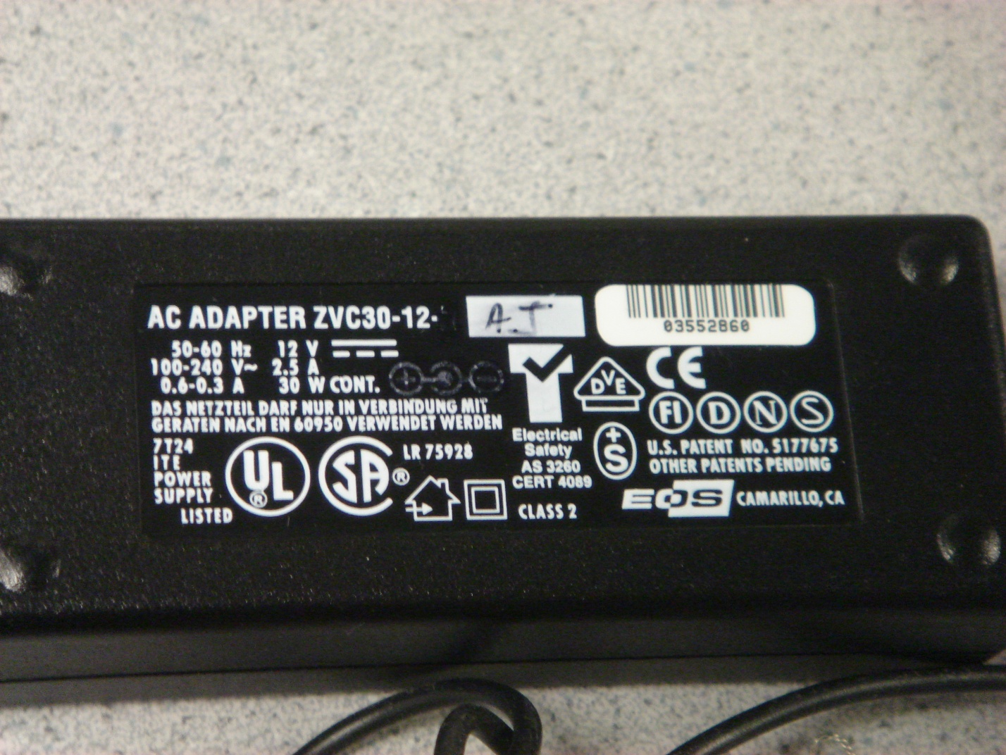
The power supply we use:
Software Part
The software part is relatively easy to implement and debug. Although our PID algorithm is really complicated, there is no complex data flow so it is not hard to implement. The most important part of software is thus determining the PID parameters. After trial and error, we finally decide our PID parameters to be ![]() ,
,![]() and
and![]() .
.
Previous Attempts
We have tried a lot of different schemes for mechanical parts before deciding on the final design. Here are our previous designs.
1. The very first design. This design can prevent the horizontal movement and the rotation of the plate. However, it will not provide enough levitation force.
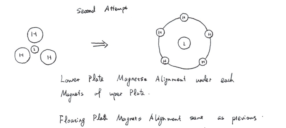
2. Our second try. This design can confine the plate well in the position with magnet force alone when there is not much outside disruption. It can also provide considerable levitation force. However, it is extremely unstable under larger disruption. In addition, it requires a lot of magnets, which exceeds our project budget. WhatˇŻs more, directly putting coils around neodymium magnets will not work since they are hard ferromagnetic material.
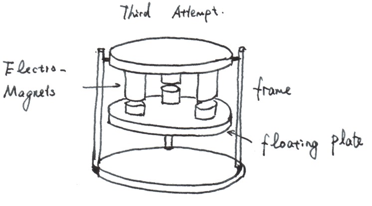
3. The third design. We used a different idea, rather than pushing the plate up, we can try pulling it up. However, the system is still not intrinsically stable and from our calculation, PID control will not respond fast enough to keep the system stable.
We also tried to use LME49720 as the pre-amplifying stage op-amp. However, it requires a much more complicated circuit design to actually get most out of it. So we changed back to LM358.
Results of the Design
Speed of execution:
Our programˇŻs execution can be adaptively adjusted to an appropriate level by controlling the prescalar of Time0. If we use prescalar 1, the reaction speed of the system will be amazingly fast, however, the floating plate may quiver more due to PIDˇŻs self-adjusting property and the fluctuation of 1-5 even when the accelerometer is static. If we use prescalar 8, the reaction speed of the system is still reasonable, even is much slower than prescalar 1. The best thing of prescalar 8 is the quivering is reduced a lot and the system is very stable under normal conditions. The larger prescalar we can use is 64. However, if we use prescalar 64, the systemˇŻs reaction speed will be so low that makes it not practical at all. After testing, we decide the best PID parameters to be![]() ,
,![]() and
and![]() . With these parameters, the longest time for the system to balance the floating plate is about 1 second. The time can be reduced if we place a lighter weight or put the weight close to the center of the plate to make the floating plate incline less.
. With these parameters, the longest time for the system to balance the floating plate is about 1 second. The time can be reduced if we place a lighter weight or put the weight close to the center of the plate to make the floating plate incline less.
Accuracy:
In previous experiments we put the upper floating plate on a perfect horizontal floor and read the outputs of the two accelerometers (of course, used as horizontal sensors in or design). And we get the found the accelerometersˇŻ values to be 764 and 782 when the floating plate is exactly horizontal. There is some small difference between the two outputs when the plate is horizontal because we found the wooden board we bought is not perfectly flat. Because we simply fixed the target x and y output values to be 764 and 782 separately, the PID algorithm will always try to make the real feedback values to be close to the above two values. So our system is very accurate when the system reaches its desired target feedback values. However, two factors inversely affect the accuracy of our system:
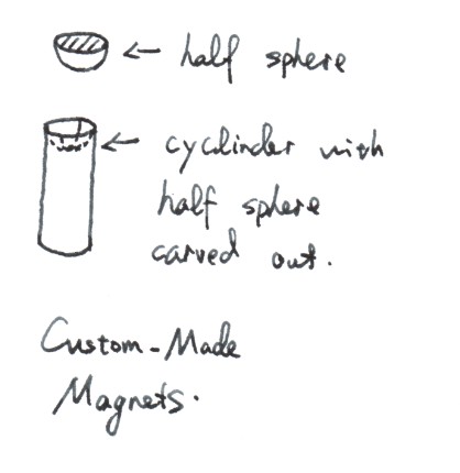
- The friction between the magnets and the brass tubes cannot be ignored and can be significant without appropriate lubrication. At first when we didnˇŻt use any lubricant, when an electromagnet tries to pull the floating plate a little bit, it will gradually increase its output due to PID algorithm. However, the floating plate still keeps its original position due to friction until the pulling force becomes very large. But now the pulling force is much larger than the pulling force when the floating plate is balance and the plate will again incline towards this electromagnetˇŻs direction. Then the electromagnet will try to decrease its pulling force and it wonˇŻt be effective until the pulling force becomes very small due to friction and then the plate will suddenly rise up in this electromagnetˇŻs direction. So what we will see is the plate keeps bouncing around. And friction can severely decrease the accuracy of our system. This problem can be solved by using custom made magnets. We think we can place hemispherical magnets on the floating plate and put magnet rods with hemispherical concave on the top, whose diameter are the same as the hemispherical magnets or a little bit large. After that the plate can float on the base without any confinements like the brass tubes and the friction is eliminated. However, custom made magnets are so expensive that we cannot use them for our project at all.
- As we have said above, even if the accelerometer is kept at a fixed position, its output value will still fluctuate within 1 to 5. Even this fluctuation only indicates a change in the inclination angle which human eyes can barely see (our maximum value is 1023), The PID algorithm will still try to adjust the floating plate because we fix the desired feedback values to be 764 and 782 separately. ThatˇŻs why the floating plate quivers. The quivering becomes more significant when the prescalar is small because the adjusting speed is fast. This problem can be solved by using a more accuracy accelerometer or using a smaller range accelerometer of about 0.5g (instead of 1.5g in our design). This part can also be further improved.
Safety:
Safety consideration is very important in our project due to mainly two reasons: 1. High voltage, which can be as high as 36 volts. 2. Very strong magnetic field, which is harmful for both electronic devices and human if get exposed for a long period.
Electric: Once the air broke down when we placed the probe of the multimeter very close to both +24V and -12V and the spark it generated lighted up our whole workbench, which is really dangerous and all three op-amps of the three channels were very easily to be destroyed. After that we add wooden paper isolation between the power op-amp and the LM358 because the heat sink of the power op-amps has a negative voltage of -12V. Another important thing is the electrical wires should not be peeled too much. Peeling the wires too much will make them easy to create short circuits. A short circuit at 36V can easily burn op-amps, transistor, other device or even yourself if you touch them because they will be extremely hot. Also, cleaning up the whole workbench before putting the soldered boards on it is also very important because even small cut wire fragments can easily create short circuits on the soldered side of the board and wipe out the devices. Try to plug the wires into sockets as much as possible to avoid both bad connections and short circuits. Another trick might be used is the sequence of plugging in the three power supplies. In our project, to plug in the -12V power supply first, then the +24V power supply, and finally the +12V power supply is the best and safest way of plugging in the power supplies. After that, rail voltages should always be affirmed to make sure the circuit will work correctly.
Magnetic: The magnetic strength in our project wonˇŻt be harmful to human if one only get exposed for a short time but can be very harmful to electronic devices like computers. So when working on the project one should keep all spare magnets away from all electronic device, especially for devices with hard drives like computers and iPods. Sticking unused magnets on steel cabinets of the lab is a good ways because there are a lot of magnetic materials around the room like tweezers, pliers, screw drivers or even banana clips. All these things may ˇ°automaticallyˇ± fly to your magnets because the neodymium magnets are so strong. One bad thing is even the neodymium magnets are plated with nickel to make them less fragile, it also makes them highly conductive. In this way if banana clips which are connected to wires stick on the magnets, unexpected short circuits may occur and thatˇŻs what we donˇŻt like to see. Always keep oneˇŻs hand away from several magnets that are not stuck together. The strong magnets may pinch human fingers, which is REALLY PAINFUL!
The above are the two main safety issues, and there are also other safety issues:
- Turn off soldering stations after you finish, and keep the soldering ironˇŻs tip away from your and othersˇŻ hands.
- Masks should be used when using the dremel tool to cut wood because the wood dusts can be harmful to your lungs.
- Sound-isolating ear buds or custom-made earphones should be used when using the dremel tool to cut metal because the noise is absolutely terrible.
- Wear safety goggles and keep all people away from the rotation direction of the dremel tool because the high-speed rotating wheel may break and hurt people.
- Avoid breathing all chemicals. For example, direct inhalation of lubricant WD-40 might be harmful or even fatal.
Interference with other peopleˇŻs designs:
Even if our project contains big electromagnets whose total power can be as high as 80 watts, it wonˇŻt interfere with other peopleˇŻs designs because its frequency is too low to generate RF waves. During the whole lab periods we didnˇŻt found any conflicts between our project and other groupsˇŻ project. So our project is very neighborhood-friendly.
Usability:
Our project is very easy to use. One just needs to plug in the power supply and turn on the chip and the system and PID algorithm will do all other things. Other things a user may do is just putting some weight on the board or shaking the base and the system will automatically balance the floating plate. So our design is absolutely user-friendly.
Commented code and other files
A program that tests the electrical and magnetic parts: dacsweep
Our program that implements PID algorithm: Control
Another program that implements a simpler PID algorithm with less response range but is more stable: Simple_Control
Single-step balancing program for basic ideas: Basic_Ideas
The original .max files for mechanical design: Mechanical_Design
To Go Further
Our project is by no means perfect since there are hardly any previous examples, so for those who want to further extend the project, we have some suggestions.
- Use some other hard material for the platform and the base. One of the major hindrances of the accuracy of our project is that the platform is not flat since wood is very sensitive to the environment. We still choose wood because it is easy to get and process it. Teflon will be a much better choice to increase the flatness.
- Use custom-made magnets instead of bronze tube to avoid horizontal movement of the floating plate. In our design, we used bronze tube to prevent the floating platform from moving sideways due to our project budget constraint. This adds considerable frictions even though we used lubricants. A better design might be using custom-made magnets. One example is as follows.
- Use a better accelerometer for tilt sensing. We used a 1.5g accelerometer for our project which is donated by Freescale. 1.5g is way too large a range for our project since our tilt angle will not be even greater than 30 degrees, so the output voltage swing is relatively. A 0.5g is a good choice for the project that can increase the accuracy and noise rejection a lot.
- Use better op-amps. LM358 and LM675 are very classic op-amps. They are relatively easy to use and we get free samples from national semiconductors. However, there are always better ones. LME49720 and LM4675/LM3875 are a higher level pair that is very suitable for the project4
- Adding active anti-shock function. Originally, we sampled some magnetic sensor from Ohio Semitronics to implement active anti-shock but gave up because of time constraint. With our present project, it is very easy to implement anti-shock function by adding another PID controller using the magnetic sensor output.
Conclusion
How the results meet our expectations:
In our original imagination, you can fiercely shake the base and the floating plateˇŻs position is still fixed. However, our systemˇŻs responding speed is not that fast as we expected but is still reasonable. The system still has anti-shock and balancing function, but just not that fast as we imagine. After we did a detailed analysis, we found several reasons may contribute to the imperfectness of our result:
- The electromagnetˇŻs magnetic strength decreases sharply if we increase the distance between it and other magnetic materials. And the pulling force of the electromagnet is almost ignorable if the distance is more than 1.5 centimeters. So we cannot shake the base that fiercely as we imagine because if the distance is more than 1 centimeter, the system would not be able to effectively control the floating plate very quickly.
- We have six neodymium magnets, three iron rods and two accelerometers on the floating plate, which make the plate extremely heavy. So its inertia is very large and even if the accelerometers give out the information of ˇ°tiltˇ±, the electromagnets cannot change the position of the floating plate immediately. And this is another factor that contributes to the slowdown of the systemˇŻs reaction speed.
If I can do the same project next time, I may use purely pulling force to levitate the floating plate. It means that we use three electromagnets to pull the floating plate up from above and totally eliminate any pulling force. This can make the floating plate lighter because we only need to place three iron rods on the plate instead of three iron rods and many pieces of magnets. However, to balance the plate is not simply enough now because we also need magnetic sensors to control to distance between the iron rods and the electromagnets. At first we tried to use our sampled HR72 magnetic sensors to implement but later we found it was not that applicable because the measuring range of HR72 is too large so we think magnetic sensors with range of 1000 Gauss will work well. Another consideration is the power supply. We need more powerful and cleaner power supply for the above design because electromagnetic force becomes the only force that both adjusts the floating plateˇŻs position and conquers its gravity. More complicated PID algorithm may also be used to shorten the systemˇŻs response time due to the instable equilibrium of the system: Without appropriate external force it will fall to the ground. So the only problem for this new design is, if it is used in real applications, normally it has the function of balancing and anti-shock, however, during emergency conditions like earthquake, the power is lost and the plate will simply fall to the ground! We donˇŻt want to see this so secure backup power supplies must be used.
The designˇŻs conformity to the applicable standards:
Our design conforms to all standards very well. We use standard Gauge 28 magnetic wires to build the coil and use three standard 110V AC to 12V DC power supplies. All these things are widely used and easy to find. Even without any power, our system still has part of its anti-shock function, but not as effective as when power is supplied because pushing magnets act like springs. However, the system totally loses its function of balancing the floating plate when it loses the power. Also, our design is much easier to implement than the above ˇ°newˇ± design so it is very practical.
Intellectual property considerations:
Our project explores a brand new field in active anti-shock system. Before starting our design, we have neither previous designs as references nor other peopleˇŻs code. So we spent a lot of time on deciding possible scheme of the system. We also did a lot of small experiments to test the applicability of different mechanical schemes and sensors. And obviously there are neither patent nor trademark issues. All our sample parts are from National Semiconductors and Ohio Semitronic. The receptionists are very friendly and helpful and we got the samples easily without signing any non-disclosure contracts. We donˇŻt think applying for patent is realistic because this is only a ˇ°first generation designˇ± in magnetic active anti-shock system. However, to publish what we have done is good because we should let people know our result and further improve the design. This field has lots of room for development and improvement.
Ethical considerations:
First our thought of designing this anti-shock system is aimed at reducing damage to precision devices due to physical shocks. If the final design is successful, a lot of devices can benefit from it. The public safety hazard can be decreased to minimum if the electric and magnetic fields are appropriately shielded. All of our results are based on real experiments we made and are highly reliable. And after designing this system we found there are enough room for potential development so we donated our $702 spared magnetic sensors to our Professor Bruce Land for other groups to make future improvements. If anybody has any criticism on our design or want to further improvement on our design, we would like to discuss about possible error and share our experience with people who will improve our design. If other groupˇŻs improved design is similar to our design in mechanical parts, we can also donate our mechanical parts to them. The project is very complicated in building circuits and enough-precision mechanical parts by hand so group work and assist are absolutely necessary. During the whole designing, building and testing process we did almost everything together and helped each other. For this project, only people with enough expertise can understand and further improve it involves both complicated hardware and software of feedback control system so we can maintain our competence in this field and make the design safe to normal people.
Legal considerations:
The only consideration is whether the EM field our electromagnets generate might be harmful to human body or not. After checking FCC regulations, we found there are only safety EM field exposure limitations for EM waves whose frequencies are higher than 300KHz. However, the frequency of the EM wave generated by our design is much lower than this range so there are no legal considerations about this.
Cost List:
Part number |
Vender |
Price |
ATmega644 |
Atmel |
$6 |
Custom PC Board |
Bruce |
$4 |
Solder Board (6 inch)*3 |
Bruce |
$2.5*3=$7.5 |
Small Solder Board (2 inch) |
Bruce |
$1 |
DIP Sockets*4 |
Bruce |
$0.5*4=$2 |
Pins |
Bruce |
$0.05*100=$5 |
Power Supply 12V*3 |
Bruce |
$5*3=$15 |
Wooden Boards |
Cornell Store |
$6 |
Brass Tube |
Cornell Store |
$1 |
Magnets |
EBay |
$1*9=$9 |
MMA2260D Accelerometer |
Donated by Freescale |
Free |
LM358*3 |
Lab |
Free |
LM675*3 |
Sampled from National Semiconductor |
Free |
Bolts |
Winter Lab |
Free |
Total |
|
$56.5 |
Budget Available |
|
$75 |
Work Distribution
Original Idea |
Weiqing Li, Boyi Ma |
High Level Design |
Weiqing Li, Boyi Ma |
Mechanical Parts Design |
Boyi Ma |
Electrical Parts Design |
Weiqing Li |
Mechanical Parts Construction |
Boyi Ma, Weiqing Li |
Electrical Parts Construction |
Weiqing Li, Boyi Ma |
Electrical Parts Debugging |
Boyi Ma, Weiqing Li |
Software Basic |
Weiqing Li, Boyi ma |
Software Debugging |
Boyi Ma, Weiqing Li |
|
|
Final Calibration |
Weiqing Li, Boyi Ma |
Final Report |
Boyi Ma, Weiqing Li |
Vender Sites and Datasheets
Vender Sites:
Atmel: http://www.atmel.com/
National Semiconductor: http://www.national.com/
Ohio Semitronics: http://www.ohiosemitronics.com/
Freescale: http://www.freescale.com/
Datasheets:
LM358 Op-amp: http://www.national.com/an/AN/AN-116.pdf
LM675 Power Op-amp: http://bdml.stanford.edu/twiki/pub/Haptics/VibrationImplementation/LM675.pdf
MMA2260D 1.5g X-axis accelerometer: http://www.freescale.com/files/sensors/doc/data_sheet/MMA2260D.pdf
ATMega644: http://www.atmel.com/dyn/resources/prod_documents/doc2593.pdf
HR72 Hall-effect magnetic sensor: http://www.globalspec.com/GoTo/GoToWebPage?Context=Part:Precision+Hall+Effect+Probe+--+HR72&gotoURL=http%3A%2F%2Fwww.ohiosemitronics.com%2Fpdf%2Fcatalog%2FHR.pdf&gototype=TocPartWebPage&VID=91356&Comp=4144
Special Thanks
Thanks to Bruce Land for providing helps and advices during the whole semester and all the lab devices.
Thanks to Tim of Winter Lab for providing steel bolts and helping us processing mechanical parts.
Thanks to Ohio Semitronics for providing HR72 magnetic sensor samples and supporting our project.
Thanks to National Semiconductor for providing free LME49720 and LM675 op-amp samples.