|
ECE 4760 – Spring 2011 |
|
Final Project: Ultrasonic Spheroid Levitation Device |
|
Adam Yozwiak (awy23) and David Zlotnick (djz28) |
|
Thursday Lab Section 5/1/2011
|
Table of Contents
Design Compliance with Expectations
Intellectual Property Considerations
Videos
Introduction
The goal of this project was to design and build a ‘gaming’ device capable of levitating a ping pong ball at varying heights based on the proximity of the user to the device, utilizing a multi-tasking kernel on the ATMega16 platform.
The project incorporates a fairly complex mechanical system and utilizes many features of the ATmega platform including Analog-to-Digital conversion, SPI communication, Pulse Width Modulation, and real-time task scheduling. The designers, both electrical engineers, wanted to break the norm and build something more physically complex as the project involved a lot of physical construction, using materials like wood and Plexiglas. The game is intended to require significant physical motion on behalf of the participant, in the style of a Wii or Microsoft Kinect game.
High level design
Rationale
The true inspiration for this
project was derived from a future project the designers intend to build in
their spare time, during senior week. This project, a pneumatic, range-sensing
soda can launcher will utilize the same sonar sensor and 7-segment display
featured in the levitation game. Taking into account ABET criterion for senior
design projects, the soda can launcher was tabled, and the levitation game was
designed – originally utilizing compressed air to levitate the Ping-Pong ball.
A valve capable of regulating the output pressure of a compressed air tank
proved too costly for the budgetary constraints of this project, and therefore
several blower motors were tested for their adequacy based on their air volume
movement ratings (CFM).
Intended to be both entertaining and interactive, the levitation game will be fun for children and adults alike, it is bright, loud, and attractive to those who are curious regarding the fundamentals of flight and the Bernoulli effect. Designed to sit on a tabletop, the game currently requires a large DC power supply to run the blower motor, but a 120v adapter could be easy incorporated if the game were to be more portable. The state machine diagram below shows the logical operation of the game. OCR2 is the PWM register (set to 0 delivers full power to the fan, set to 255 turns the fan off). When the gameStart flag = 1, all tasks are enabled, when gameStart = 0, only the checkSwitches task is enabled.
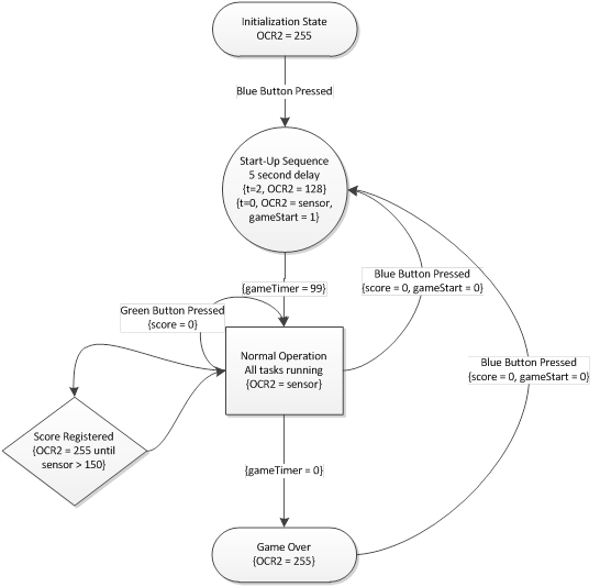
Figure 1: Game State Machine
Background Physics/Math
The overarching physical principle behind the functionality of this project is Bernoulli’s Principle which states that for the flow of non-viscous fluids, an increase in speed of the fluid occurs simultaneously with a decrease in pressure. Applied to this project, as a high-speed stream of air is directed at a ping pong ball, the air molecules diverted around the ball speed up and therefore exert less pressure. Higher pressure air molecules surrounding the stream exert a restorative force on the ping pong ball, in the direction of higher to lower pressure. Therefore, if the ball is knocked off its equilibrium in the center of the air stream, it will be directed back toward the center by this restorative force.
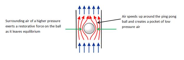
Figure 2: Bernoulli Effect
To establish this high velocity stream two fan types were considered, axial and radial (centrifugal) fans. A quick comparison of these two fan designs indicates that centrifugal blowers are capable of delivering greater pressure throughout the range of air flow volumes. This sustained pressure is key for maintaining ball levitation even while varying the rpm of the fan.
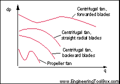
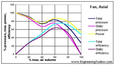
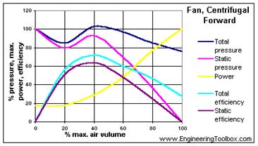
Figure 3: Fan Pressure Responses
Furthermore, the power output/consumption of centrifugal fans is proportional to the amount of air they are moving. This quality makes them ideal for linear PWM control – since higher voltages and therefore higher current draw corresponds to increased power output.
Logical Structure
Care was taken to ensure the design was as simple, efficient, and as safe as possible. Beginning with the choice for a power source, a current-limiting power supply was chosen over a standard 12 volt battery. While a power supply is more cumbersome to operate than a 12v battery, it offers short circuit protection as well as impulse dampening. If a 12V battery was in use and during testing a hot, and ground wire came in contact – the results would be catastrophic. Furthermore, the power supply allows us to limit the current while testing our PWM circuit. It is vital not to exceed the current ratings of the power transistor or the fan, so having control over the maximum current draw was quite useful.
All of the electronics selected for this project were chosen for their modularity and simplicity. Utilizing the TinyRealTime task-scheduling kernel, the software aspect of the project shares the same modularity of the hardware, which makes testing individual components as simple as commenting out a line of code, or removing a connector from the white board.
Finally, potential circuit failure modes were considered during the design process. Instead of taking the output from the photodiode (used for keeping score) and using this to trigger an external interrupt on the microcontroller, it was connected to a port pin which is checked several times a second. Since the photodiode-opamp circuit has the potential to become unstable and oscillate wildly if it loses calibration, this would result in an ISR being called so much that it would block the other functions of the CPU and halt the operation of the game. Also, to ensure the bilge blower has sufficient current to run at full capacity, we utilized heat sinks and a cooling fan directed at the BUZ71 power transistor – since its current output capability drops drastically as it heats up. All switches are connected through grounds, to be sure the 12v hot line is isolated away from user interaction points.
Hardware/Software Tradeoffs
The game logic and peripheral control is handled in software by the ATmega16 microcontroller running TRT. There are no digital logic circuits external to the microcontroller, responsible for logic decisions. There are two embedded controllers used in the project: an ATmega328P which is integrated into the 7-segment display and is capable to of decoding SPI signals into the proper format for driving the display and a PIC controller which drives the sonar sensor. The overall input/output scheme is diagrammed below:
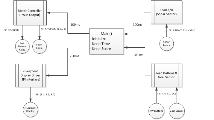
Figure 4: High-Level Input/Output Diagram
Considering the fact that the game operates on a human time scale and the limitations of the hardware sensors and displays, each task need only execute 10 times per second. The sonar sensor is capable of updating its analog output every 100milliseconds, and the seven segment display operates at 9600 baud. The hardware buttons simply connect a port pin to ground (the port pins are held high by pull-up resistors) when pressed. The software reads Port C every 100ms to determine if any of the buttons are depressed, and reads PIN D2 to determine if a goal has been scored (the photo sensor outputs a logic high – 5V signal when the beam is blocked by the ball). Every 100ms the A/D conversion value is read and the register is reset so that the next value can be accessed when the task is called again.
The hardware
output interfaces include a Pulse Width Modulated (PWM) signal to control the
speed of the main blower fan, a digital output pin to trigger the 12v relay for
the auxiliary fan, and a three-wire Serial Peripheral Interface (SPI) to
control the 7-segment display. The duty cycle of the PWM output is updated
every 100ms, allowing for a smooth response between sonar readings and blower
velocity. Since the auxiliary blower is engaged based on the sonar readings,
the digital output enabling or disabling it is also updated in the task
governing the PWM output. Since the variables outputted to the 7-segment
display are score and game time, there is no point to updating the display more
than a few times per second – thus a 250ms delay between task calls was chosen.
Both the game time and score are broken into separate 8 bit (char) variables
for each digit, then grouped into 4 byte (32 bit) packets and sent along the
SPI interface.
Applicable Design Standards
Serial Peripheral Interface (SPI) is a full-duplex signaling standard developed by Motorola. The standard utilizes a master-slave configuration requiring the master device to output a clock signal which is used by the slave device for timing and synchronization. For this project, the ATmega16 microcontroller offers a built-in SPI interface; likewise the 7-segment display peripheral is designed to interpret SPI signals and thus the standard is strictly adhered to by the embedded hardware. The clock frequency used was 125 kHz (or clk/1024), is set to idle low, and sample on the rising edge (see program design section for additional SPI initialization details). Since there is only one slave device, the Slave Select (SS pin) could be wired to ground, however connecting it to the slave select pin on the microcontroller ensures that the peripheral is only listening when the MCU is transmitting, thus reducing the possibility of noise interference on the line.
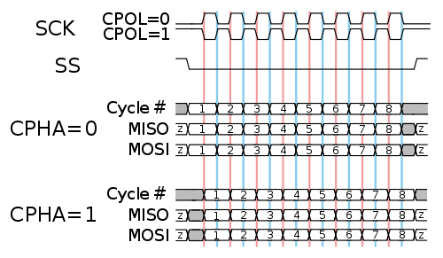
Figure 5: SPI Timing Diagram
Hardware Selection/Design
Fan Selection
In order to achieve an air steam capable of levitating a ping pong ball, a fan with high air volume and static pressure was required. Several fan styles were considered for this project including axial, radial, and tunneled axial. The first fan tested was a standard 80mm square 12VDC computer fan, rated at 45CFM pictured below.
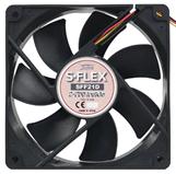
Figure 6: Axial Computer Fan
After a few seconds of testing, it was quite clear that this style fan would not provide enough static pressure to levitate a ping pong ball. After attempting to collimate the stream down to two inches, most of the air was being blown back through the fan blades as opposed up at the ball.
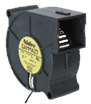
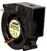
Figure 7: Radial Blower Fans
Next, a radial (centrifugal blower) was tested, two sizes were used: 2.5cfm and 25cfm. While both of these fans were more promising than the axial blower, it was apparent we would need significantly more air flow to achieve the desired result – ping pong levitation up to 24”. The last and final fan type considered was an axial tunnel blower – which combines facets of both fan designs.
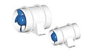
Figure 8: 240CFM Bilge Blower
This type of fan is used in marine applications to evacuate diesel fumes from boat engines. This blower is rated for 3.5 Amps @ 12VDC and will deliver 240CFM at full capacity – the current demand is significantly higher than what a whiteboard will support, so we needed to design a PCB in order to handle the higher current load. The ‘bilge blower’ is mounted in a tunnel and therefore produces a well-collimated stream of air, as shown in the picture above.
Once the fan had been chosen, a proper outlet port and 90degree connector was needed to ensure the ball levitation was stable and could reach an appropriate altitude. Several PVC pipe bend sections were salvaged from a now defunct engineering project team. Both 3” and 4” pipe bends were tested. The 3” bend caused the fan to draw more current at lower RPMs, limiting the total air flow possible without exceeding the fan motor’s current rating. Thus, it was decided that the 4” pipe bend was the best option to maximize airflow. With this bend alone, the ping pong ball would only levitate about 6”. Several outlet ports were tried in order to see which maximize ball altitude while minimizing the back-pressure and current draw of the fan. The image below shows the first configuration, a 4” to 3” down converter, with a 2” diameter pipe, and a round outlet pattern – while this configuration worked well to stably levitate the ball, it did not achieve a great altitude since the back-pressure limited the fan’s output.
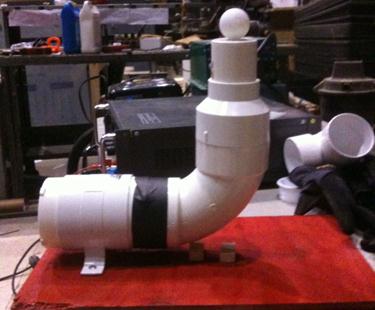
Figure 9: 4" 90deg Bend with 3" adapter and 2" Circular Outlet
The next configuration removed the 4” to 3” down converter and simply consisted of a 3” circular pattern outlet port (show below) directly connected to the top of the 90deg bend.
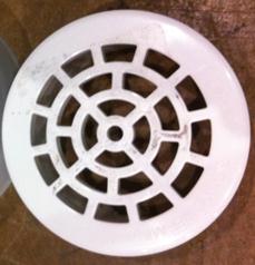
Figure 10: 3” Circular Pattern Outlet Port
The 3” outlet reduced the current draw required to maintain maximal air volume, but did not quite allow for the desired ball altitude. The last and final outlet tested was 4” in diameter and features a grid of square holes. While this outlet was not quite as stable as the circular pattern, it did provide the greatest ball altitude and thus it was chosen for the final design.
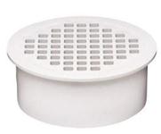
Figure 11: 4" Square Grid Outlet
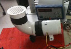
Figure 12: 4" Square Outlet Installed on Blower
Sensor and Display Selection
Once the ball levitation system was perfected, design work on the sensors and displays began. To measure the distance of the user from the device, both sonar and infrared sensors were considered. IR sensors where cheaper but were limited in range and accuracy, while sonar offered people detection at distances up to 15 feet in 1 inch increments. Furthermore, there are readily available sonar sensors with easy-to-interface-with packages, which made configuration and testing a breeze, and allowed us to focus on other aspects of the project. The sensor we chose, the Maxbotix LV-EZ1 is sold by SparkFun and costs $25.95. Although this model is about $15 more than a non-driven sonar device, the built in circuitry is not only capable of driving the speaker and receiving the sonar pulses, but it translates the signal into SPI, RS232, or an analog voltage. Furthermore, the device is self-calibrating on power-up and will adapt to its environment, limiting ranging error. This functionality is incredibly desirable and saved countless hours of development by removing the need for a sonar-driver circuit and an additional D-to-A converter.
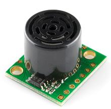
Figure 13: Maxbotix LV-EZ1 Sonar Range Sensor
Maxbotix offers several low-cost sonar range sensors, each with a different calibration and expected beam pattern. Since our project involves human body interaction, a fairly narrow beam was desirable, in addition to a range of 10-15’ and resolution of 1-6”. The LV-EZ1 was specifically designed to detect human-sized objects, as opposed to other sensor models which are calibrated for wall or doorway detection. It offers detection from as close as 6” up to 254”, and all of the output options discussed above. In order to maintain simplicity and free-up the serial communication ports of the MCU for other peripherals/debugging, the analog output is used. The analog output is scaled in increments of VCC/512 per inch of sonar resolution. Since we are powering the sensor with the 5V voltage regulator on the ATmega target board, the maximum voltage of this output is (5V/512)*254in = 2.48V. This works nicely with the internal 2.56V reference voltage offered by the ATmega16 MCU. Setup and initialization of the sensor was fairly simple, VCC and ground are connected from the sensor to the MCU. The analog output port on the sensor is connected to pin A.0 on the MCU, and the A/D converter is initialized to use the internal reference voltage, align the result left, use channel 0, and set the prescaler to clk/128.
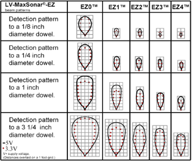
Figure 14: Maxbotix Sensor Ranging Chart (Excerpt from Datasheet)
The display chosen for this project was a 7-segment display sold by SparkFun. Although it is more expensive than using an LCD display, it offers a built-in blue backlight and is much brighter and easier to see than the LCD display. Since the user is required to back away from the device substantially after scoring in order to reset the blower control, it is imperative that the user is able to see the game countdown timer.
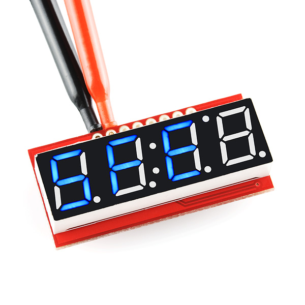
Figure 15: 4-Digit 7-Segment Display (SPI Controlled)
The device utilizes SPI for communication which requires 3 port pins rather than the LCD which would require the entire port. The first two digits are used to display the game score, the center color is enabled to help the user distinguish between the two numbers, and the right two digits display the game timer which counts down from 99 to 0 (seconds). The device recognizes 4-byte packets, each byte corresponding to a number 0-9 or a hex letter a-d. Furthermore, the device allows individual control of each of the 7-segments per digit, allowing the user to define interesting animations or other characters which are otherwise unsupported by the built in character map.
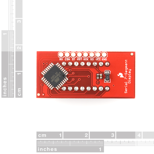
Figure 16: 7-Segment Display (Rear View)
The connections required are clock (SCK), Master-out Slave-In (MOSI), and Slave Select (SS), VCC, and GND. The corresponding MCU ports are visible in the table below:
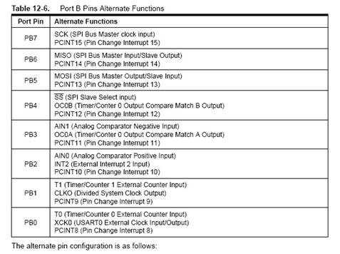
Figure 17: Port B Alternate Functions (Excerpt from Datasheet)
PWM and Photo-sensing Circuit
The blower PWM control circuit was adapted from the circuit used for the class Lab 4. The circuit diagram (shown below) is the same as what was used in lab, with the exception of the BUZ71 transistor, which was substituted for its additional current carrying capacity. The BUZ73 transistor is rated for 7 amps nominal, while the BUZ71 can handle 14 amps. In testing, the BUZ73 would become extremely hot and so heat sinks were added to the top of the device. The heat sinks enabled the device to pass more current and allowed the fan to move more air. Upon switching to the BUZ71, and installing a small 12 volt blower fan to keep the device cool, the fan was able to draw its full, rated current load of 3.5 Amps. The circuit was initially tested on a white board with a much smaller 12 volt fan. Since white boards can only handle a few hundred milliamps, a circuit board was built using the RadioShack solder boards provided in lab.
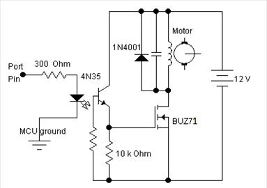
Figure 18: PWM Circuit Diagram (Lab 4)
To assure ampacity, 20 gauge wire was used for all connections within the board, and 18 gauge wire was used to transmit the main 12v and ground connections from the power supply. The 4N35 optoisolator protects the MCU from high energy transients such as inductive spikes caused by the motor.
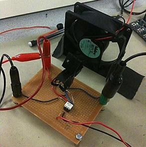
Figure 19: Custom Built Solder Board
The PWM carrier frequency was set to clk/1024 to make sure the bandwidth of the optoisolator does not limit the transmission of the PWM signal. The signal is connected to the gate of the BUZ71 and biases it so it conducts proportionally to the duty cycle of the signal. Furthermore, the motor acts as a large inductor in the circuit and thus low pass filters the signal so that each duty cycle width (from 0 to 255) corresponds to a voltage from 0 to 12 volts (or the power supply voltage).
Initially, the design for registering a goal would be accomplished with micro switches purchased from SparkFun. Unfortunately, these switches required more force to engage the trigger than a falling ball could provide. Increasing the length of the trigger helped slightly, by offering more leverage, but the ball would simply get stuck in the goal instead of falling through and triggering the switch. After attempting some other fixes with springs, and complicated mounting schemes, it became apparent that mechanical triggering would be too complex to assemble and calibrate. The next option considered was photoelectric detection. The circuit used in lab 4 to detect the rpm of the fan was perfect for this application. It offers hysteresis and signal amplification thanks to an op amp configured for positive feedback. In lab 4, the infrared LED was used to bounce light off of a fan painted partially white. This reflected light was picked up by a phototransistor, and was used to drive the op amp to its upper rail, based on a user calibrated threshold set by a potentiometer.
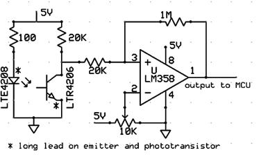
Figure 20: Photo detection Circuit (Lab 4)
To properly register a goal, the emitter and phototransistor were mounted in the hoop, pointed directly at each other. While the phototransistor has infrared photons incident on it, it is turned on, and drives the voltage low. As soon as the emitter is blocked by a falling ball, the phototransistor turns off, and the voltage jumps up to 5 volts. Since the ball’s decent is limited by terminal velocity, the shortest this pulse will be is about 70 milliseconds. Accordingly, the software task which reads the port pin, can be set to run every 100 milliseconds. The emitter and sensor mounting is shown below:
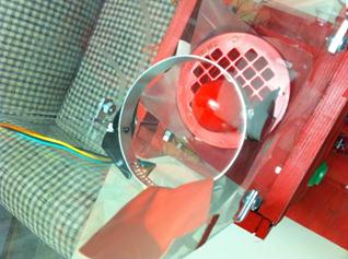
Figure 21: Hoop with IR emitter and phototransistor
Auxiliary Fan Relay Circuit
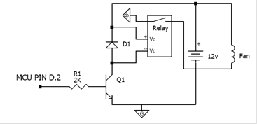
In order to add another dynamic element to the game, a second 12v blower was mounted to blow perpendicular to the main levitation stream. When engaged, the secondary blower limits the altitude of the ball, and can cause other interesting ball motions such as orbiting. The main purpose of the secondary fan, however, is to aid the user in scoring a goal. The fan is triggered when the sonar sensor reports that the user is within 15” from the game board, or when no user is detected (> 150”). To control the 12v, 0.30A blower via a MCU port pin, an external relay driving circuit was necessary. The relay used was a standard, mechanical, automotive relay, with a 12v control and 12v load. The circuit uses a N3904, NPN transistor, and a diode to protect against current spikes from the relay (see schematic below).
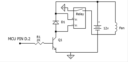
Figure 22: Relay Driver Schematic
When the MCU port pin is set to high, the transistor is biased on, and conducts to ground, which puts 12v on the relay control pins and triggers it on, connecting the auxiliary blower to ground. For testing/debugging purposes, a green LED, in series with a 330ohm resistor was wired in parallel to the MCU pin. Thus when the fan is running, the LED is illuminated.
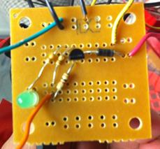
Figure 23: Relay Driver
Game Construction
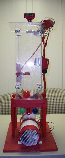
The initial design for the game structure, shown on the left, incorporated a cylindrical pvc tube, which proved to be too expensive to source for this project’s constrained budget. Instead, a square tube was constructed using L-brackets and thin acrylic sheet cut into (4) 20” by 6” lengths. The original design also called for several goals which would be triggered by the ball’s erratic decent. Upon testing, it was determined that the ball fell in the approximately the same place every time, therefore the multiple goal idea was scrapped, and a single ‘hoop’ goal was adopted. To get the ball in the goal, a secondary 12v blower was mounted about 1/3 of the way up the game and angled to blow air horizontally across the playing field. This secondary blower is engaged when the user gets within 15 inches of the game, or if no user is detected.
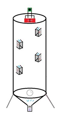
![]()
The base was to be constructed out of bendable aluminum rods, however wood was chosen as the final material since it is much easier to manipulate and secure. A piece of plywood was cut to make a strong base for the blower fan and the rest of the assembly. The fan produces significant vibrations,so a steady base was necessary to make sure the other components would not be affected. Two small blocks of wood were cut and glued to the plywood base in order to support and level the 90deg pipe bend. Six inch length of 1-by-2 were cut and fastened together with screws to make a base for the acrylic square tube. The acrylic was affixed to the wood frame with (8) ¼” bolts, to make it removable. Finally, (4) 8” lengths of the 1-by-2 were cut and fastened to the plywood base from underneath.
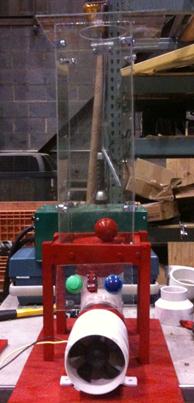
Figure 25: Completed Game Board
All of the wiring was the shortened to an appropriate length, soldered, and taped down to the base to make sure the game looked clean and orderly. The reset, clear, and master power buttons were hot-glued onto another piece of acrylic, then mounted to the front of the device. The wiring from these buttons was bundled together and ran around and up the legs of the acrylic tube, to the top of the device where the microcontroller is mounted. Also, small triangles were cut from thin aluminum stock and affixed around the bilge blower outlet, to make sure the ball did not get stuck in a corner, and could be quickly reset. Finally, two holes were drilled into the scoring hoop, and the IR emitter and sensor were mounted directly across from each other. The hoop is presently affixed to the inside of the tube with tape, so it can be easily repositioned, but a more permanent way of mounting the scoring hoop will be investigated.
Program Design
Program Details
The project’s program was designed to fit into TinyRealTime task scheduling architecture. The program consists of an initialization/idle task, four regularly scheduled tasks, one interrupt service routine, and one function that can be used by any of the scheduled tasks. The program code can be found in full, in the appendix.
Initialization/Idle Task
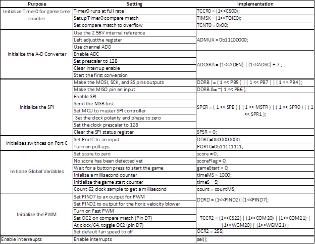
The initialization and idle routine are handled in the program main task. The MCU initialization occurs though the following configuration setting to the AtMega16 internal registers:
The initialization task also creates a semaphore which protects variables shared between multiple tasks with:

New TRT kernel tasks are created in the initialization routine via the following code:
![Text Box: // --- createtasks ----------------
trtCreateTask(getSonar, 150, SECONDS2TICKS(0.1), SECONDS2TICKS(0.15),&(args[0]));
trtCreateTask(update7Segment,150,SECONDS2TICKS(0.2),SECONDS2TICKS(0.3,&(args[1])); trtCreateTask(checkSwitches,150,SECONDS2TICKS(0.35),SECONDS2TICKS(0.38),&(args[2]);
trtCreateTask(blowerController,150,SECONDS2TICKS(0.40),SECONDS2TICKS(0.42),&(args[3]));](Final_Report_files/image033.png)
The first argument to the function call trtCreateTask is the task name, followed by the task stack size, the initial release time, the initial deadline, and the pointer to the arbitrary argument vector.
getSonar
The getSonar task is used to read the microcontroller’s ADCH register to get the newest ADC sample, samples if the user is in close proximity to the game, and averages this sample with the previous two. The reason for low pass filtering the samples is to prevent damage to the bilge blower by providing it a slower varying control voltage. The other function of this task is to control the auxiliary blower relay if the user is very near (< 15”) or very far (>130”). This game parameter was tweaked by the designers to maximize the game’s fun factor. Once the sample was read from the buffer, a new sample was started by setting the ADSC bit in the ADCSRA register. This task only performs these functions if the gameStart flag was set, indicating that the game is in “play” mode. The getSonar task is scheduled to run 10 times per second.
update7Segment
The update7Segment task takes a variable Ain (assumed to be less than 1000) and transmits this number over SPI to the seven segment display. The update7Segment task only does this following if the gameStart flag is set, indicating that the game is in “play” mode. In order to do update the display, the variable Ain needs to be decoded from its base-10 representation to an integer which represents the ones place, an integer that represents the tens place, and an integer that represents the hundreds place. The update7Segment task follows the following decoding scheme:
|
|
Ain < 10 |
10 <= Ain < 100 |
100 <= Ain < 1000 |
|
Ones |
Ain |
Ain mod 10 |
Ain mod 10 |
|
Tens |
0 |
Ain / 10 |
(Ain mod 100)/10 |
|
Hundreds |
0 |
0 |
Ain/100 |
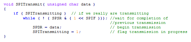
A supporting transmission function was used to interfacing the ATmega16 (master) to the ATmega328 seven segment display driver (slave) over SPI. This function was found (as well as the SPI register configuration) from Pololu Robotics and Electronics website at http://www.pololu.com/docs/0J9/2.
The ATmega328 slave looks for SPI transmissions in 4-byte blocks (one byte per seven segment, unless using special codes). For this reason, SPITransmit is called four times for one update of the 4-digit seven-segment display. This task is scheduled 4 times per second.
checkSwithces
The checkSwitches task looks for two buttons to be pressed or the IR goal sensor to be active and also holds the code for the startup sequence. This task is scheduled every 100 ms to query PortC (where the switches are connected) and PortD (where the IR sensor is connected) to see if there is an input to the program. If the Blue Button is pushed (Pin C.0), then the game is reset by beginning resetting the score, setting gameStart = 0, and startupSequnce = 1. If the green button is pressed (Pin C.1), the score is reset.
If the IR sensor is tripped (Pin D.0), the game assumes that the ball passed through the hoop and a point was scored. In order to prevent one goal from scoring multiple points, a delay was added such that after a point was scored, the checkSwitches task needs to run another 5 times before the score can again change. This effective .5s delay is more than enough time to allow the ball to pass through the hoop. Also, to make the game more enjoyable, triggering the score sensor sets a flag scoreFlag and squashes the PWM signal until the user steps back (~5ft in the test environment).
If the startupSequnce flag is set, the checkSwitches task sends a 5s countdown timer (accumulated from timer0) to the seven segment display using the SPItransmit() subroutine. This routine also contains simple logic for a game countdown timer which is displayed to the seven segment display using SPItransmit(). When the countdown timer reaches zero, the program prints “dEAd” to the seven segment display.
blowerController
The blowerController task updates the OCR2 register which sets the PWM speed for the bilge blower control. In general, the OCR2 register gets a scaled (1.25x) version of the sonar sensor’s distance measurement. However, to make the game more enjoyable, the motor cuts off is the sonar measurement is greater than 120 (~10’) or is set to full speed if the measurement is less than 25 (about ~2’). This task is scheduled 10 times per second.
Program Design Modifications
Several of the initial concepts changed for this program changed through the design process. For example, the goals were initially detected through an interrupt service routine that triggered when the photodiode op-amp circuit detected a goal. During testing we realized that the sensor has the potential to become unstable and oscillate if it loses calibration. This caused the ISR to be triggered at a very high rate which consumed the CPU and essentially never gave our tasks time to finish and haulted the game operations.
We also had to change the names on almost all of the MCU registers when we transferred our program from the ATmega644 used in the STK500 to the ATmega16 used on our target board. This was not a difficult change, but it did consume debugging time when we realized that MCU registers were also initialized and updated in the TRT files.
Results of the Design
Speed of Execution
As mentioned in the program design section, the game uses the real-time TRT kernel for multi-tasking threads. The speed requirements with this project were not particularly demanding on the CPU because the game only needed to “fast-enough” for the user. The following table shows the design compromise for scheduling the TRT tasks between performance and “fast-enough:”
|
|
Scheduled Freq |
|
getSonar |
10 Hz |
|
update7Segment |
4 Hz |
|
checkSwitches |
10 Hz |
|
blowerContoller |
10 Hz |
Safety
The most dangerous element to our game is the 50W bilge blower used to levitate the ball. However several safety features were designed to mitigate the risk to the designers and users. First, the soft (plastic) blade is completely enclosed in the PVC pipe and is covered by a metal shield at the inlet to guard the blade from hurting the human body. To minimize the risk of using a heavy-duty power supply, the current limit was always set at 4 Amps (just enough to run the fan motors. Finally the fan blade will not even start unless the power is on, the MCU is on, and the game start button is pressed. Safety considerations drove the selection of a 12V DC fan motor over a similar fan which used 120V AC power.
This game involves full-body movement by the individual. To maintain an atmosphere safe for this type of play, the user must ensure that the immediate space in front of the game is free of clutter in order to prevent tripping while playing.
All lab safety rules were followed while designing, integrating, and testing this final project. Protective glasses were worn while cutting wood and acrylic, both partners were present when using power tools, and circuits were verified by a second party before power was ever applied for the first time test of a board.
Usability
This game does not produce any sort of electrical interference for other groups in the lab. The sonar sensor operates at 42Khz which is above the range which humans can hear and well above the vocal range, as several other groups have implemented microphones for various voice manipulation projects. The most interfering component to our design is the acoustic noise created by the bilge blower. Many fans were tested, however only this high-power fan moved enough air to levitate the pong ball sufficiently for the game. Most of the testing of the fan game was done at the Cornell High-Voltage Lab enabling a quieter atmosphere for students in the lab.
Conclusions
Design Compliance with Expectations
The final project performance met all of the requirements set forth in the initial project proposal; including the course mandated budget and schedule requirements.
The final project uses a fan to levitate a ball as proposed in the initial design. This proposal requirement was perhaps the most fundamental part of the project and yet the most difficult to attain. Four fans and five types of balls were evaluated until the designers were comfortable with a fan/ball combination that could repeatedly control the ball’s height from the fan outlet. Fortunately, the fan that was purchased which did not meet the projects levitation requirements was worked into final design to recover the “research and development” costs associated with the fan experiments. Had we suspected we would need a high power fan to levitate a small ball, we would have sought samples or in-kind gifts.
There were very few, if any, hitches in setting up the sonar and the seven-segment SPI peripherals. Each of these devices was configured and evaluated in about one 3-hr lab period and worked as specified in the associated documentation.
The designers did not anticipate that the presence of goals in the game would significantly disrupt the fan’s air flow field. This led to a design which had fewer (only one) goals than envisioned in the proposal. Given more time, the designers would have engineered more creative, slimmer profile, goals in the game to make it more fun.
Applicable Standards
As discussed in the High-Level Design, this project uses the Serial Peripheral Interface standard for communication between the ATmega16 master microcontroller and the ATmega328P microcontroller which drives the seven segment display. For this project, the ATmega16 microcontroller offers a built-in SPI interface; likewise the 7-segment display peripheral is designed to interpret SPI signals and thus the standard is strictly adhered to by the embedded hardware. Learning this standard made the communication interface easy between the two MCUs and also introduced the designers to a universal protocol which they will likely use in future microcontroller projects.
Intellectual Property Considerations
No code from this project was reused from a previous ECE 4760 project; although the ADC conversion was referenced from ECE 4760 Lab 3 and the PWM initialization was referenced from ECE 4760 lab 4. This final project also used the fan motor power circuit, the IR emitter and phototransistor amplifier circuit, and the real time TRT kernel from ECE 4760 Lab 4. Code for transmitting over SPI was referenced from Bruce Land (in class) and http://www.pololu.com/.
At this time neither designer sees a potential patent or publishing opportunity for the project.
Ethical Considerations
Throughout the design process we have strived to meet all expectations and best practices expressed by the IEEE Code of Ethics. This report serves to identify and disclose, to the best of our knowledge, all safety and health factors that may endanger the users of this game. All claims made in this report and through verbal and email correspondence to TAs, Professors, and classmates, regarding the performance of our design has been, and will continue to be, honest, fact based, and objective. The designers have designed a game meant to be fair to people of all persons regardless of race, religion, gender, nationality, and age. The designers were fair in the selection and procurement of components as to not be biased by conflict of interests or other factors that would give one vendor an unfair advantage over another. The designers also acted professionally and in accordance with all expressed lab rules during the time in lab and sought to actively help other students to promote a safe and intellectually stimulating lab environment. Finally the designers understand the limitations of our project, have done our responsibility in expressing those limitations in this report, and are open to comments and critiques of the project.
Legal Considerations
Our project is a simple table-top game. It does not release significant RF energy and should not cause any interference with other electronics.