A Portable Automated Bird Trapping Mechanism
ECE 4760 Final Project
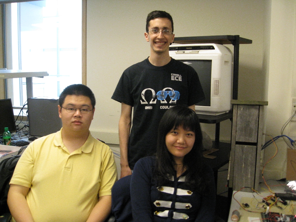
Cindy Huang (qh33), Jeff Lebovici (jdl226) and Ian Zhang (yz258)
Contents
Background
High-level design
Software/Hardware design
Results
Conclusions
Lessons Learned - Advice for Future Groups
App A - C Code
App B - PHP Code
App C - Schematics
App D - Cost Details
App E - Task Breakdown
Pictures
References
Background
We designed and implemented an automated, portable bird-trapping mechanism, along with an associated system which is scalable.
|
Every year between early May and mid-June large amounts of tree swallows migrate to Ithaca, NY area to mate. The study of these birds invariably require a large number of specimens to be captured for purposes such as sample-taking, banding and measurements. The current method to capture a bird includes affixing a latch, attached with a fishing line, to the entrance of the nestbox that the birds nest in, waiting from as far a distance from the nest as the fishing line/field of vision of the nest would allow for the birds to land in the nest, and pulling the latch across the nestbox entrance with the fishing line. This is a time-consuming and labor-consuming process that can take up to an hour for the capture of one bird. The long waiting period is largely due to the fact that tree swallows have exceptional vision and are highly sensitive to potential predators (humans) in the vicinity of their nests; they will delay return to the nest as long as the rate of eggs cooling or chicks feeding requirement would allow when such potential predators are present in sufficiently close proximity to their nests. In addition to cost concerns the prolonged human presence in the field could also impact neighboring nests by increasing stress levels of the tree swallows in those nests as well as other organisms in CURP. Thus, an automated trapping device that could be hidden from the birds would be beneficial the study of tree swallows by increasing efficiency of bird trapping, greatly reducing manual labor, and decreasing stress to the tree swallow population as well as impact to the local ecosystem.
|
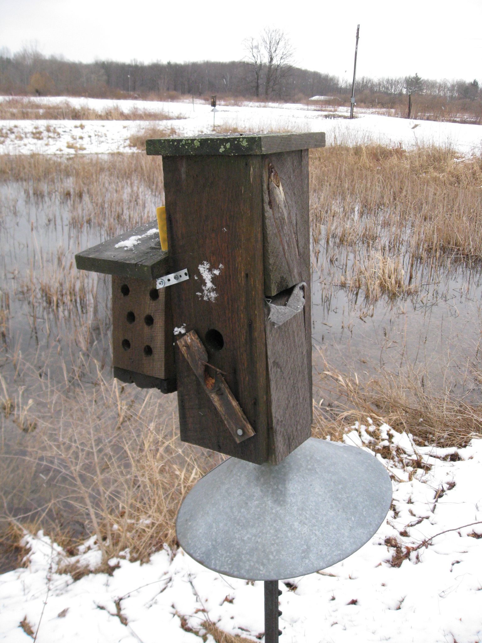
Figure 1 The original nestbox. This trap must be manually triggered.
|
High level design
Our bird-trapping mechanism (BTM) is an attachment to the existing nestbox with an extended section for camera housing, and a modified latch for mechanical bird trapping. The Atmel Mega644 microcontroller is the brain behind the BTM. Via a passive infrared (PIR) sensor, the Mega644 determines when a bird has entered the nestbox. Upon trigger, it drives the Maxx 400 servo motor to close the latch, in addition to enabling a notification at a centralized base station.
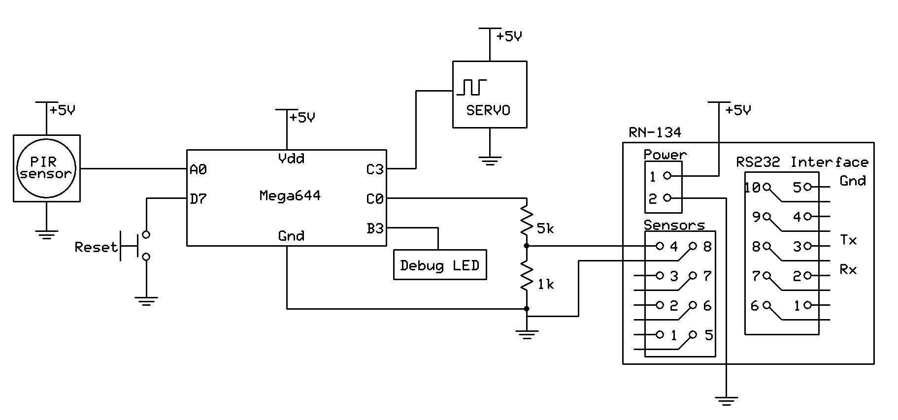
Figure 2 Top-level schematic of a portable bird trapper.
|
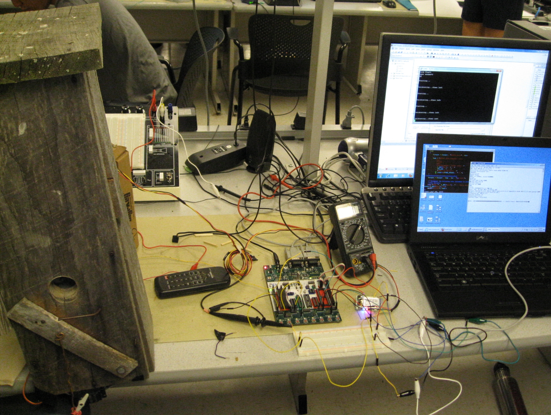
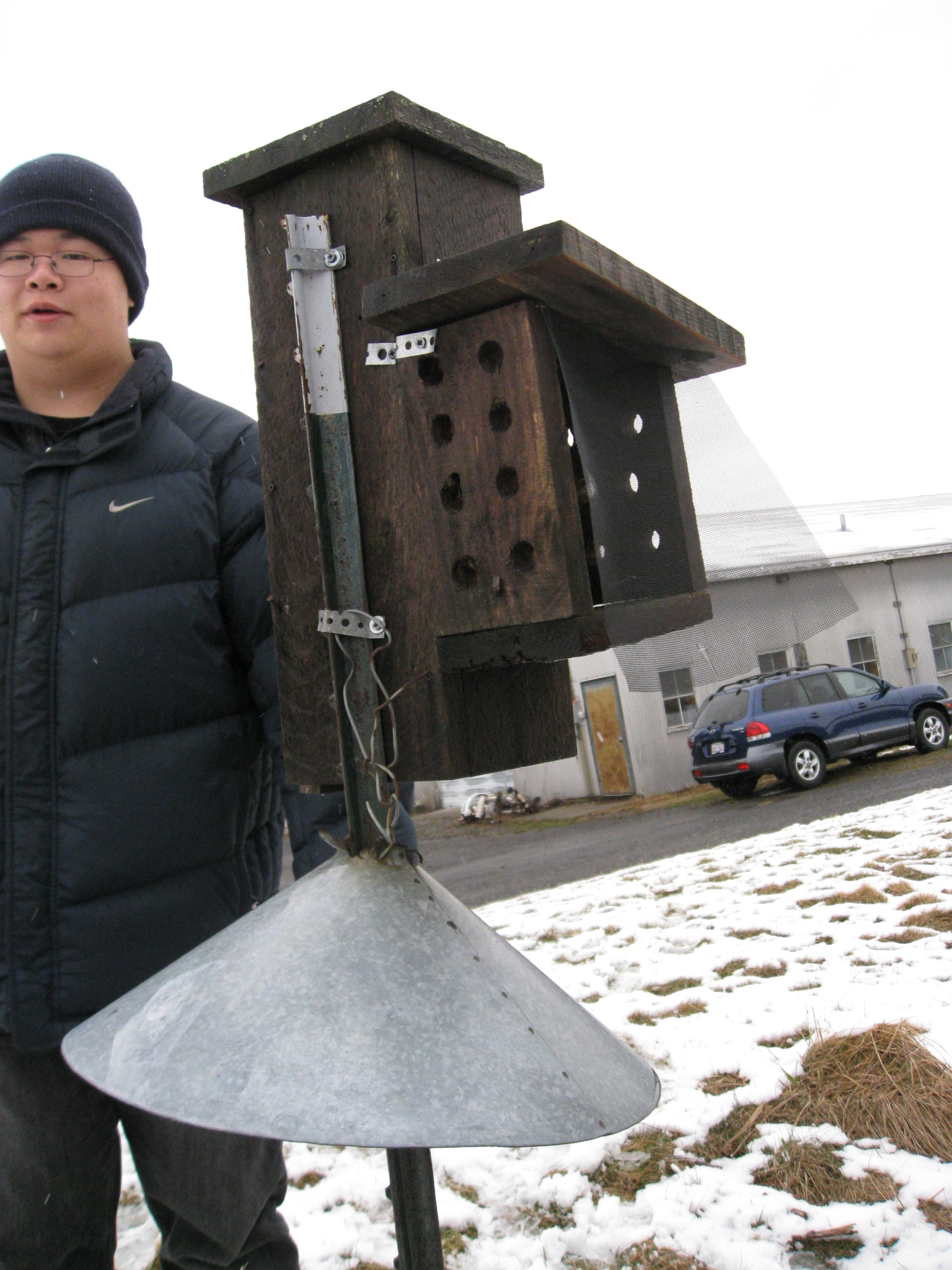
Figure 3 Our implementation of an automated portable bird trapper.
|
In order to make this trapper portable, we want to remove the user from the minutia of waiting by a trap for a bird to approach. The most straightforward way to accomplish this is to centralize the waiting. This is possible through a system which monitors and reports on any significant trapper activity.
We chose to accomplish this by WiFi-enabling our trapper. The site where the trappers will be implemented is already WiFi accessible, and by operating entirely within the bounds of the 802.11 protocols and standards, we do not have to worry about formatting or transmitting data at the low level. The part we used to WiFi enable our device is the Roving Networks RN-134 (hereafter "RN-134") SuRF Board. From the manufacturer's description, the board "is a field ready, WiFi certified 802.11 b/g solution." In addition, the board can be operated via either RS232 or TTL UART interfaces. Given our previous in-lab experience with both communication protocols, we were comfortable integrating this part into our design.
The RN-134 operates by periodically waking and transmitting a heartbeat to the central server. This heartbeat includes enough data for the server to represent the current state of the trapper to the end-user.
The webserver is written in PHP, a high-level scripting language used to dynamically generate web pages based on user input and records stored in a backend database. The server runs on the XAMPP platform, which is an easy-to-install packaged implementation of a LAMP server. While the initial plan was to use a single HTML page which reported the status of one trapper, we found that by using these web development tools, we could implement a system which is informative and scalable. Using the state received by the RN-134, the end-user can observe if a trapper has caught a swallow and/or is not responding. This will allow the user to interact with trappers which need attention, without handling trappers which are functioning nominally.
|
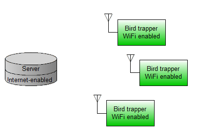
Figure 4 | High-level depiction of a complete bird-trapping system.
|
| Each green box is one bird trapper, Figure 2. |
Software/hardware design
Servo Motor
The servo motor used is the Maxx 400. It has an operating voltage of 5V and is controlled through a PWM signal. It turns from 0 to 180 degrees with a neutral position of 90 degrees. The turning angle is determined by the duty cycle of the pwm it receives. Theoretically the servo is expecting to see a pulse every 20 ms, setting the pwm frequency and 50 Hz and the neutral angle is obtained at 1.5ms width pulse. 0 degree is reached at 600us pulse with and 180 degree at 2400 us width. Here to obtain the maximum performance with the available pwm frequencies from mega644, we’re using 62 ns pwm pulses. The PWM we output from the Mega644 has a range from 0 to 255, with 0 corresponding to a full duty cycle and 255 corresponding to an empty duty cycle. We can resolve 37 discrete positions by controlling the servo with the PWM. PWMs of widths (255 – 8) and (255 – 45) correspond to the physical limits of the servo motor. We drive the servo between two positions: PWM widths of (255 – 8) and (255 –30).
The servo motor is powered by a 5 V supply and is controlled through port B3 of the Mega644 controller using its Timer0 PWM. It is mounted on the bottom side wall of the nestbox on the side of the bird entrance using plumber's tape. The servo motor is attached to the latch using a piece of 12 gauge wire. The wire is attached to the latch by twisting it to loop through an existing hoop on the latch used in manual trapping. On the servo motor side, the wire is wrapped around the arm with a combination of a loop on the 12 gauge wire and several turns of 22 gauge wire. The result is a rigid connection between the latch and servo motor arm, while keeping a slight degree of slack on the connection points (Figures 5 and 6). The precise location setting of the servo motor was achieved through trial-and-error by first moving the arm without attaching the latch until an approximate range was established, and fine-tuning with the latch attached. Positioning was deemed acceptable when it could open and close the latch without straining either the latch or the servo motor.
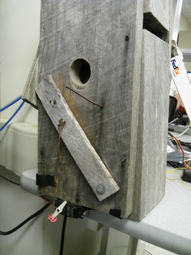
Figure 5 The latch, open.
|
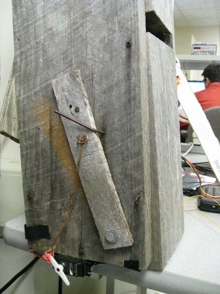
Figure 6 The latch after actuation, closed.
|
PIR sensor
The PIR sensor used is the Parallax PIR sensor. It outputs a logic low (0V) when not triggered and a logic high (3.5V) when triggered. It has two modes of triggering, selectable by moving a jumper cable, it could either keep output high while repeatedly triggered or repeatedly pulse. For simplicity, the first option is used.
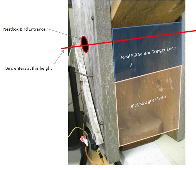
Figure 7 Illustration of the ideal PIR trigger zone.
The sensitivity of the sensor initially gave us quite a headache. A warm-up phase, which varies from 0 to 60 seconds, calibrates the device. During this period, any motion (and in our experience, even sound!) will jeopardize its ability to properly detect motion. No concrete time for this initialization is given in the documentation, so we pass through a "safe" period upon system startup: 40 seconds during which nothing can trigger, and the device should be left completely still.
We tried multiple solutions to provide the PIR sensor with a very quiet and protective environment for it to warm up. Initially, we covered it with a PCR cap to confine its environment. Although this proved effective, the fact that we were mounting this inside the bird nest made this solution unnecessary. It turns out that the dark and confined environment of the nest provids very good "pre-operation protection" for the sensor.
Our second challenge was the starting high phase. While testing, we detected that after warming up, the sensor will start high for about 10 sec and then revert back to its initial low status. Since we set the Mega644 to react to a high signal when a bird is caught, the high starting phase returns a false positive. The problem is solved by enforcing the 40 second delay in software. Since the Mega644 cannot handle continuous delay for more than 15 sec, we break up the 40 seconds into 4 phases. We found that the signal will reliably fall back to its nominal state within this 40 second period.
A concern for the operation of the BTM is that it will be used largely in the summer months, during which the interior of the nest can have significantly elevated temperatures. Thus the concern exists that the PIR sensor may be triggered by the temperature. The datasheet for the Parallax sensor mentions that the sensor should only trigger on temperature gradient, and that uniform heating of the nestbox should not affect the sensor. Since the BTM will be used to trap live animals, we conducted tests to ensure that the sensor is not tripped on increased outside temperature. We used a hair dryer to heat up all sections of the outside of the nestbox to simulate increased outside temperature. We noted that unless the hair dryer is pointed directly into the bird entrance of the nestbox at extreme close proximity, the PIR sensor is not triggered.
Our final hurdle was the significant sensitivity of the sensor. The sensor’s range is approximately 20ft, and as long as the sensor is on, any motion, even light or sound may trigger it easily - there is no thresholding device embedded on the sensor. Motion from a feather, wood strand or fiber is enough to trigger the sensor. One possible solution was to put an incandescent lid on top of the hemispherical sensing surface in order to filter the light passing through it, so as to lower its sensitivity and make it trigger only when obvious motion is presented. Positioning also matters, since the sensor can detect changes over its entire hemisphere. As long as we position it such that only 20-30 percent of the surface is available to trigger, false triggering can be minimized. The small hole - intended for a camera - above the nest enables us to mount the sensor with the optimized position. Tests proved that false triggering was reduced to about 2%, a large improvement from the 50% false-positive rate beforehand.
RN-134 Configuration
The RN-134 allows us to automate a module of the system which we thought would require manual communication between the Mega644 and the RN-134 via UART. It is set up to broadcast to the server periodically, regardless of whether the BTM has triggered. This is to assure an operator who is monitoring the web site that the trapper is still functional. In order to configure the RN-134 to this behavior, two connections had to be established: personal computer to RN-134, and RN-134 to server.
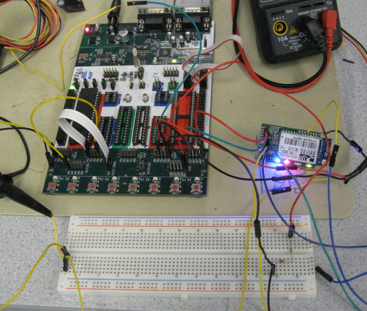
Figure 8 | Closeup of the RN-134 attached to the STK-500 development board.
Establishing a connection to a personal computer was surprisingly difficult. The RN-134 has a built-in adhoc mode, which can be set via a jumper. Once adhoc mode is enabled, any computer can connect via Telnet to the RN-134 on a local network hosted by the RN-134. However, with the RN-134 serving as an access point, it cannot access the internet. Upon obtaining a wired connection to the RN-134, we would obtain the following benefits:
- Instant feedback.
Perhaps the most significant benefit, the RN-134 provides useful output regarding the status and success of a wireless connection. If a transaction fails, we are able to observe both ends of the communication. Were this not the case, we would only be able to observe whether the server updated information correctly. This would be fishing for a symptom without knowing the problem.
- Minimized debugging time.
The RN-134's adhoc network takes approximately 60 seconds before being connection-ready. We observed this delay even when attempting to configure the RN-134 to connect to another access point, execute the transaction (severing the adhoc link), and then reestablishing the adhoc connection. This meant that every time we wanted to test a new configuration, we had to wait an arbitrary amount of time until we again saw the adhoc network.
(As an aside, these transactions were not successful, and we never figured out why, as we could not see the useful output described in item #1!)
We therefore made it a priority to establish a wired connection to the RN-134. We settled on an RS232 connection via a serial DB9 connector. One end of the link is stripped, exposing the transmit (Tx), receive (Rx), and ground wires to connect to the RN-134's pins. Although this is a simple solution with as few stages between the PC and the RN-134, it we settled on it only after experimenting with several other methods of communication.
Before discussing the steps we took to establish this connection, it is worth noting how the STK-500 development board handles incoming RS232 signals. The STK500 has two DB9 interfaces. One is reserved for programming the Mega644. The other, entitled "RS232 Spare," takes input from the PC and converts it to (0 V, 5 V) TTL levels:
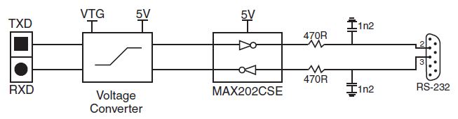
Figure 3-10 from the STK-500 User Guide.
TTL UART
Initially, we wanted to establish the connection without "harming" any hardware in the lab. Given our previous success in this course with the TTL UART capability of the STK500 development board, we originally intended to set up a UART connection between the STK500 and the RN-134. However, we were delayed by an inconsistency in the RN-134 datasheet. The datasheet explicitly notes that the Rx and Tx UART through-hole labels were erroneously swapped during production. On the other hand, the labeling of the RN-134 PCB is inconsistent with the image on the datasheet. When initially connecting the STK500 UART to the RN-134, it is possible that we wired the connection incorrectly and damaged the RN-134's UART interface. We were not successful in establishing this UART connection.
RS232
Once we decided to use the RS232 interface on the SuRF board instead of the UART through-holes, we needed a way to convert TTL signals back to RS232. We used an available MAX233 to accomplish this conversion. Note that minimal RS232 protocol requires no flow control, and only the Rx, Tx and Gnd pins are necessary for complete communication.
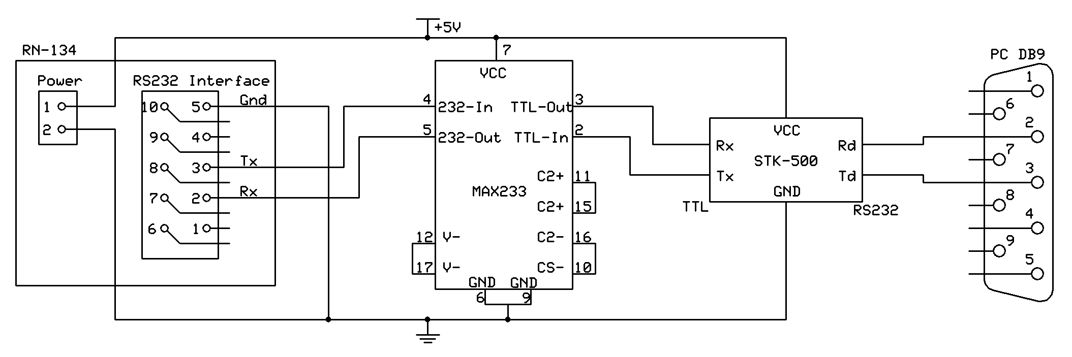
Figure 9 Circuit for converting STK-500 TTL signals to RS232.
The computer did not receive any signals from the RN-134, nor did the RN-134 respond to transmissions from the computer. We would have continued to debug this circuit, had we not been presented with a DB9 connector which was already stripped, exposing the wires for the Rx, Tx and Gnd pins. Thus, the final iteration of this connection is:
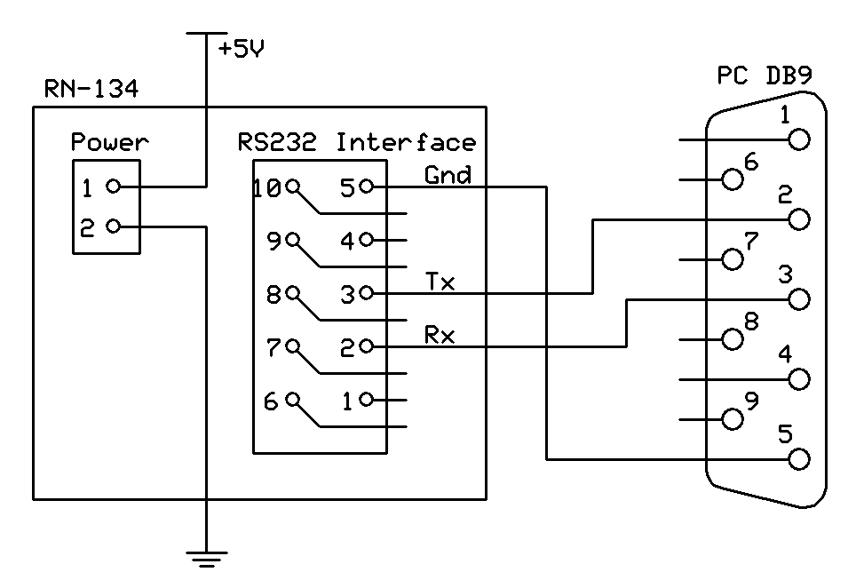
Figure 10 Final wired interface to RN-134
This is the interface which we used to configure the RN-134. It is not necessary to maintain this connection during trapper operation (note that the DB9 port is absent in Figure 2). A terminal connection to the RN-134 will display whether each attempt to contact the data server is successful, which may be useful for onsite debugging if a laptop is available.
Sensor through-holes 4 (Sensor 7) and 8 (Sensor Gnd) are used to probe if a bird has been trapped. Sensor Gnd is connected directly to the Mega644's ground, but care must be taken when connecting Sensor 7. The sensors on the Mega644 have a strict maximum rating of 1.2 V. We built a resistive divider consisting of 1k- and 5k Ohm resistors, dividing the 5 V signal of the Mega644 to a safe 0.8 V.
Following is a listing of all the RN-134's settings which were changed from their factory values or are essential to operation. Note that commands are represented as entered into the RN-134 during configuration. The dollar sign character '$' is read by the RN-134's parser as a space.
| Command as entered | Remarks |
| set com remote GET$/submit.php?DATA= | The beginning of the content of the HTTP message to be sent to the user-end server. Data and identifying information is appended via "set opt format," below. The HTTP-terminating double-newline is appended by the RN-134 parser. |
| set ip dhcp 1 | Enables DHCP, which allows the access point to dynamically assign an IP address to the RN-134. |
| set ip host 192.168.2.1 | Sets the destination IP address of the HTTP message. This IP address is within a LAN. |
| set ip remote 800 | Sets the port of the server. |
| set ip protocol 0x12 | Enables HTTP mode and TCP mode for sending/receiving data. |
| set opt format 0x1f | Appends the data from the RN-134's sensors, as described by the command "set q sensor". Also appends a slew of device-related data - we grab the MAC address and use it to identify the transmitting device. |
| set sys autoconn 10 | Sets the RN-134 to connect to the stored remote host every 10 seconds. When it makes this connection, it broadcasts the HTTP GET message. |
| set sys iomask 0x2070 | Setting the eighth bit in this bitmask low configures Sensor 7 as an input. |
| set q sensor 0x80 | Sets one bit in this bitmask high. The RN-134 only sends the data from the corresponding sensor (Sensor 7) to the server. (Strangely, the ASCII string is still the same number of characters. But, instead of sampling the other pins, it sends "0000".)
| | set wlan ssid billiejean | The RN-134 will attempt to connect to network "billiejean." This is purely for Internet access. Although our data server is on the same LAN, this need not be the case. |
| set wlan phrase ***** | The security passphrase for network billiejean. |
Server configuration
The PHP driving the server is straightforward. There are two ways the website will trigger:
- The server hears the "heartbeat" of an RN-134.
In this case, the server must update its information according to what it received from the RN-134. This update includes the MAC address and status of the trapper. The server appends a timestamp of the update to the data before storing it in the appropriate record. If no such record exists, a new entry with the given MAC address is automatically added.
- An end-user requests a webpage.
The server formats an informative table for the user based on the data that currently exist in the database. There are two components to each entry's status: triggering and life. Triggering describes whether the trapper indicates it has caught a swallow. Life indicates whether the a device with the corresponding MAC address has been heard from recently. ("Recently" is an arbitrary server-side value which will be tuned once trappers are implemented in the field. However, we expect a time of no more than two minutes to be defined as "recent").
Figure 11 describes the visualization of one record, while Figure 12 illustrates how the server presents multiple entries to a user.
- A user modifies a record.
Selecting the "Modify" button in Figure 12 allows the user to change the item's description or delete the record entirely.
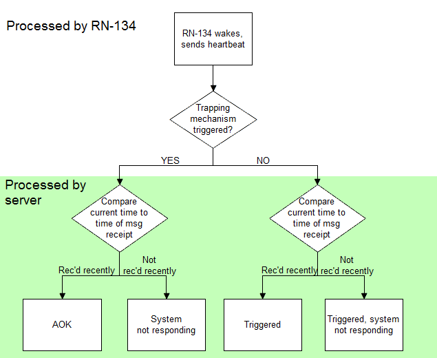
Figure 11 Diagram describing the decisions involved in displaying the status of a trapper.
|
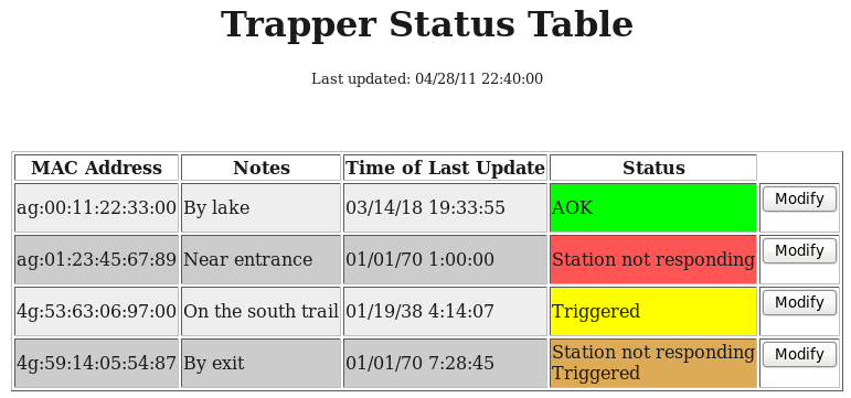
Figure 12 Screenshot of the website displaying four records, each with one of the possible statuses.
|
Note the division between what is handled in the RN-134 and on the server. By sending the minimal amount of data and performing calculations on the server, the Mega644 and the RN-134 spend the minimum amount of time transmitting. (Alternatively, we could have had the server send the current time back to the Mega644, or maintained a clock in the Mega644, thus having each station monitor time separately.)
The data sent by the RN-134 is encapsulated in an HTTP GET message:
GET /submit.php?data=CF29&mac="MAC Address"&[misc_info]
where "Mac Address" is the unique hardware address of the RN-134. [misc_info] is additional information which the RN-134 appends to the message along with the MAC address. The format of this message is analogous to a function call in a modern programming language. Once the RN-134 has sent this HTTP message to the server, the script submit.php can extract the arguments data and mac.
A listing of the PHP controlling the central server is included below, in Appendix B. Of note is the content in db_util.php, which is derived from material in the article at http://www.ibm.com/developerworks/web/tutorials/wa-lamp. This citation is explained in the Conclusions section and included again at the end of the report.
Software
The software managing the BTM is written in C, compiled in AVR Studio, and executed on an Atmel Mega644 microcontroller. The software contains two task functions scheduled to run at different intervals. Scheduling is accomplished using an interrupt service routine (ISR) of one of the 8-bit timers: timer2. Scheduling is done in the main function, which runs in an infinite loop and calls each task at preset intervals.
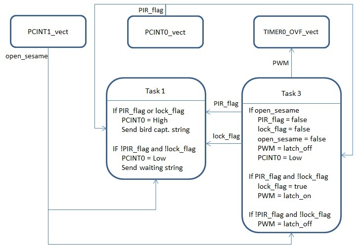
Figure 13 Overview of software architecture.
Upon startup, function initialize is called to initialize all ports and pins to the appropriate input/output states. Through UART to PuTTY, the function outputs a message "Starting..." to indicate that the program has initialized. In order to accomodate for the PIR sensor’s initialization time, four 10 second delays are added to initialization for a total of 40 second delay so that the program is not affected by the PIR sensor’s unpredictable initialization routine. For each 10 second delay that passes, a message is displayed through UART indicating how much longer initialization should take. In order to ensure that the values controlling latch operation are definitively set so that the latch does not trigger on initialization, the variable PIR_flag is initailized to false, lock_flag to false, open_sesame to false and OCR0A to 225. OCR0A is the output compare register for timer 0, the timer that manages the PWM.
The PIR sensor is connected to pin A0, which triggers a pin-change ISR and triggers every time the value on that pin changes. The pin-change ISR toggles the PIR_flag, based on which, Task 3 actuates the latch and sends message to the RN-134.
A push button is connected to another pin change ISR (PCINT1) in port B7. This ISR sets open_sesame to true, which triggers the lach reset mechanism in Task 3.
The servo motor is controlled through pulse width modulation (PWM); we use timer 0 and port B3 to generate and output a PWM signal to the servo motor. The motor position is controlled in Task 3.
Task 1
Task 1 manages communication with the RN-134. The task is run every 750ms. It checks for PIR_flag and lock_flag. If either PIR_flag or lock_flag is set to true, then it pulls PINC0 and PINC2 high; if PIR_flag and lock_flag are not set to true, then it pulls PINC0 and PINC2 low. PINC0 is connected to a sensor pin on the RN-134, when that pin is pulled high, the RN-134 is set to wake up and send a message; PINC2 is connected to an LED, for debugging purposes when using the STK500. Task 1 also displays a message through serial output to PuTTY indicating the state of the BTM; if the PIR is not tripped and PIR_flag and “lock_flag are not set, the string “Still waiting for bird is sent, if the PIR sensor is tripped and PIR_flag or lock_flag is set to true, then the debug string "Bird captured" is output over UART.
Task 3
Task 3 manages the latch; its operation is based on the variables PIR_flag, lock_flag and open_sesame. The variable lock_flag is used to ensure that the latch remains latched once the PIR sensor triggers. While lock_flag is false, the function checks for the variables “PIR_flag and open_sesame. If “PIR_flag is false, the PWM is set to latch_off, a PWM value that keeps the latch open; if PIR_flag is true, then it means that the PIR sensor has be triggered, then the value lock_flag is set to true, and the PWM is set to “latch_on, a macro that contains an output value that closes the latch. While lock_flag is true, changes in PIR_flag are ignored and the MCU continuously outputs “latch_on through the PWM. When open_sesame is set to true, the latch is set to latch_off, RN-134 trigger pin is set low, PIR_flag, lock_flag and open_sesame are set to false. This is used to reset the BTM so that the latch opens and all states are restored to when the PIR sensor is not tripped. This is used debugging and is planned to be used as a hardware reset in the field. Task 3 also sends through UART to PuTTY the current state of variables PORTC, PIR_flag, lock_flag, and open_sesame, for debugging purposes.
Results
Overall, we are very satisfied with the operation of our portable bird trapper. The response to a heated object is under 0.5 sec, and we have attenuated the sensitivity of the PIR just enough to make this response reliable. The RN-134 sends an updated HTTP message every ten seconds, and with a maximum measured five second latency, the server will never be more than 15 seconds out-of-date. The bird nest will stay closed until operator manually reset the device, ensuring that a bird cannot trip the reset and escape before a researcher appears to retreive it.
Before purchasing the servo motor, we were briefly examining two solenoids. One servo we tested was so weak, it could not close the latch. The other was so powerful, it was a safety risk. Although the Maxx 400 servo requires more complex input, it offers a greater degree of control. In addition, we tested the safety of our final product by poking a finger through the hole of the nestbox. Fortunately, there are still thirty fingers among us.
Although a layer removed from the Mega644, usability was a priority of the bird-trapping system. The web pages have been designed to be as usable as possible. All reports and forms are contain visual cues and minimize the technical expertise needed to interact with the modules. Although it is likely that someone with technical expertise will be operating the website, creating a nontechnical user interface allows tasks to be accomplished efficiently and with a shallow learning curve.
Conclusions
Results vs Expectations
In the initial project proposal, our 11 goals were:
- Detect presence of bird in the nest.
- Actuate a mechanism that seals the nest to prevent the bird from leaving.
- Send a signal to alert someone to retrieve the trapped bird and to reset the device.
- Include a manual reset.
- Have an independent poewr source good for at least 3 hours of operation.
- Installable in a way not noticeable to the tree swallows.
- Portable, installable, and removeable by one person.
- Installable without requiring excessive user experience.
- Sufficiently rugged so that careless handling will not easily cause defects.
- Unable to cause harm to any organisms interacting with it, includingg tree swallows, device operators and other nearby creatures.
- The device must follow IEE regulations and codes of ethics.
Our project sufficiently meets all expectations except for items 5, 8 and 9. Supplying the trapper with a portable power source became a lower priority as development progresses: there were more integral subsystems of the trapper which needed attention. Items 8 and 9 are interconnected. The trapper as pictured has parts secured with tape and tension. Ideally, these makeshift methods would be replaced with finely cut/marked slots where the sensor and servo could be inserted.
Future development
The next step is to make our proof-of-concept a compact, independent unit. This involves integrating a Mega644 with our peripherals, without the STK-500 development board. Once this is accomplished, we can optimize the system operation to decrease power usage. This is possible using the sleep/wake features available to both the Mega644 and the RN-134. It is also possible to lower the voltage level and clock frequency of the Mega644, further reducing power consumption. This independent unit can be installed in the camera compartment at the top of the nestbox, thus making the BTM a truly portable unit with a minimized exterior profile.
What we would do differently
Potential improvement of the device would be the addition of a camera to detect the bird’s condition and broadcast images to the web page. The operator could decide based on concrete observation what is occuring in the trap, and if it erroneously triggered.
Additional features for the website could ease management of multiple trappers. For example, the website could monitor trapper location, condition, and display photos of each nestbox to further help identify the proper device to the operator.
Since the actual device will sit in the outside environment, the pir sensor will need a permanent mounting solution. Currently we tape the connection above the wooden plate to keep the correct angle. In practice, we may want to add a wind shield to prevent false triggering, and place the sensor on a base with the appropriate angle preset into the mount.
Applicable standards / Legal considerations
Our device requires wireless transmission, a goal which can conflict with FCC regulations. However, we were careful when purchasing parts to ensure that any device we used operates solely within unlicensed bandwidth (does not violate FCC regulations). We did not modify or add to these parts. By operating within established standards, we are confident that we conform to all applicable regulations and standards.
Intellectual property consideration
We did not reuse existing code or borrow design from existing projects, with one exception. There is a SQL operation which is performed in db_util.php. Although Jeff believes that the techniques described in this tutorial are standard, he believes it is important to cite this page. This article is where he acquired the method of accessing databases via PHP which is implemented in the final design.
A publishing opportunity exists for our project. It could potentially be published in an ecology/bird journal. This will be followed up after the system is implemented at Unit 1 of the Cornell Research Ponds.
Ethical considerations
We did our utmost to ensure that we abided by the IEEE Code of Ethics. Our principle concern was to the wildlife we are inevitably affecting in the implementation of our bird trapper. Early in our design, we decided not to use a solenoid to trigger the latch, in part because it was so powerful that it might injur an animal which is perched on the nestbox. In addition, as noted in the PIR sensor section, we ensured that closing the latch will not harm the bird. Due to the dimensions of the entrance to the nextbox, the bird must be fully inside the trap before the latch triggers.
At the beginning of the project, we were honest with each other about our capabilities and areas of knowledge. We split up the tasks of development such that we would have enough of a foundation to begin working. At the same time, each of us undertook tasks which required skills we did not have, or were not well honed.
As each team member developed his skills in his area of concentration, it was important to keep the lines of communication open. This was not necessary just in order to assist each other and coordinate. If one engineer was not up-to-date in the project's specification, he would be working under false data. Not only would this waste time, but this would be a misrepresentation of what is expected by each team member. This project was a systems engineering exercise, and as we learned over the past five weeks, managing a group of people is at least as critical as managing a group of moving parts.
Due to the open-ended nature of this project, it was particularly important to abide by the principles of safety articulated in the Code of Ethics. This required carefully examining the datasheets of each part we used before removing it from its packaging. Failure to properly connect a part will result in a broken part at best. At worst, somebody could be seriously hurt.
Lessons learned for next time
- A surprisingly useful part of ECE 4760 is the non-technical aspect of the final project. We learned the hard way that a vendor is not as reliable as the shelf in lab - our advice to future groups is to hunt for parts early, and place orders as soon as possible! We lost two weeks to a vendor who failed to notify us that our part was out of stock. (We regrouped after that fiasco and ordered the RN-134 from Digi-Key. Both the part and the vendor met all our needs.)
-
We advise that after reading through a datasheet as many times as you can bare, follow up on what you read and don't understand. There were concepts in our datasheets which were foreign to us. In many cases, the Internet can be quick and helpful. However, we were not intimate with several standards (eg HTTP, RS232) upon starting this project. Had we followed up on those mysteries immediately, many of our initial problems would have been demystified.
-
The Internet can be time-consuming and misleading. Take it from Jeff, who spent a frustrating Friday unable to talk to the RN-134 because an online schematic of the DB9 interface had the Rx and Tx pins reversed! Always get a second source.
Appendix A - C Code
The following C code was compiled with AVR Studio and executed in the Atmel Mega644.
// Mega644 version
/*
NOTES
i/o
------------------------
PINB3 is output for PWM
PINA0 is input for PIR
PORTC is output for LED
timers
------------------------
timer 0 is for PWM
timer 2 is for scheduling
PWM control
------------------------
right now OCR0A is set to 128 everywhere:
PWM initialization
ISR
PIR_flag trip statement, both true and false
*/
//declaratory stuff
//***********************************************************
//***********************************************************
#include <inttypes.h>
#include <avr/io.h>
#include <avr/interrupt.h>
#include <avr/pgmspace.h>
#include <stdio.h>
#include <stdlib.h>
#include <string.h>
#include "lcd_lib.h"
#include <util/delay.h>
//set up the debugging utility ASSERT
#define __ASSERT_USE_STDERR
#include <assert.h>
// serial communication library
#include "uart.h"
///debugging
//timeout values for each task
#define t1 500
#define t3 250
#define R2 30000
#define begin {
#define end }
#define true 1
#define false 0
#define toggle(abc) (abc == true)?(abc = false):(abc = true)
// the task subroutines
void task1(void); //capacitance measurement
void task3(void); //blinks LED at rate of 1/s
void init_lcd(void); // initializes the LCD
void initialize(void); //all the usual mcu stuff
// numbers
volatile unsigned int time1, time3; //timeout counters
unsigned char led;
long int nmbr = 0;//debugging
volatile unsigned char PIR_flag = 0;
// UART file descriptor
// putchar and getchar are in uart.c
FILE uart_str = FDEV_SETUP_STREAM(uart_putchar, uart_getchar, _FDEV_SETUP_RW);
//***********************************************************
//***********************************************************
//timer 2 compare ISR
/**************************************************************************/
/**************************************************************************/
ISR (TIMER2_COMPA_vect)
begin
//Decrement the three times if they are not already zero
if (time1>0) --time1;
if (time3>0) --time3;
end
/**************************************************************************/
/**************************************************************************/
//pin change ISR
ISR (PCINT0_vect)
begin
led = led ^ 0b00000100;
PORTC ^= 0b00000100;
toggle(PIR_flag);
end
/**************************************************************************/
/**************************************************************************/
ISR (TIMER0_OVF_vect)
{
OCR0A = 128;
}
/**************************************************************************/
/**************************************************************************/
// main function: infinite loop
int main(void)
begin
initialize();
//main task scheduler loop
while(1)
begin
// reset time and call task
if (time1==0){ time1=t1; task1();}
if (time3==0){ time3=t3; task3();}
end
end
/**************************************************************************/
/**************************************************************************/
//Task 1: capacitance measurement and LCD update
void task1(void)
begin
// led = led ^ 0x01;
// PORTC ^= 0x01;
end
/**************************************************************************/
/**************************************************************************/
void task3(void)
begin;
// led = led ^ 0x02;
// PORTC ^= 0x02;
if (PIR_flag)
{
fprintf(stdout,"PIR Tripped\n\r");
OCR0A = 128 ;
}
else
{
fprintf(stdout,"PIR Not Tripped\n\r");
OCR0A = 128 ;
}
end
//Set it all up
/**************************************************************************/
/**************************************************************************/
void initialize(void)
begin
// port i/o setup
DDRC = 0b00000100;
PORTC = 0b11111011;
DDRB = 0x00;
PORTB = 0x00;
// setting PINA0 to input
DDRA = 0b00000000;
PORTA = 0b00000000;
/**************************************************************************/
// timer 2 setup for task scheduling
//set up timer 2 for 1 mSec ticks
TIMSK2 = 2; //turn on timer 0 cmp match ISR
OCR2A = 249; //set the compare reg to 250 time ticks
TCCR2A = 0b00000010; // turn on clear-on-match
TCCR2B = 0b00000011; // clock prescalar to 64
/**************************************************************************/
// set up PWM output
// timer 0 runs at full rate
TCCR0B = 1 ;
//turn on timer 0 overflow ISR
TIMSK0 = (1<<TOIE0) ;
// turn on PWM
// turn on fast PWM and OC0A output
// at full clock rate, toggle OC0A (pin B3)
// 16 microsec per PWM cycle sample time
TCCR0A = (1<<COM0A0) | (1<<COM0A1) | (1<<WGM00) | (1<<WGM01) ;
OCR0A = 128 ; // set PWM to half full scale
/**************************************************************************/
// PIR pin change interrupt setup
// pin change interrput enable, currently using PINA0
PCICR = (1 << PCIE0);
PCMSK0 = (1 << PCINT0);
//init the task timers
time1=t1;
time3=t3;
//init the LED status (all off)
led=0x00;
//init the UART -- uart_init() is in uart.c
uart_init();
stdout = stdin = stderr = &uart_str;
fprintf(stdout,"Starting...\n\r");
//crank up the ISRs
sei();
end
Appendix B - PHP Code
The following code exists on the backend of the server to manage and update trapper status.
<?php
//
// db_util.php
//
// This function handles the nitty-gritty SQL access
// to a table within a database. All the programmer has to do
// is supply the name of the database, and the SQL to modify
// the table. (A typical SQL statement will specify the name
// of the table, so this is not necessary in the function arguments.)
function sqlDB($database, $sql)
{
$db_user = "root";
$db_pass = "";
$db_host = "localhost";
// Fetch the database
$db = mysql_connect($db_host, $db_user, $db_pass);
// Execute the SQL within the database.
mysql_select_db($database, $db);
// Return the results of the query.
// (Note: this may not be applicable for all types of queries,
// such as modify/delete queries.)
$result = mysql_query($sql);
return $result;
}
?>
<html>
<?php
//
// del.submit.php
//
// This page deletes a device with the corresponding MAC address.
// Include useful predefined functions/parameters.
include 'defs.php';
include 'db_util.php';
$sql = "DELETE FROM trappers WHERE `mac` = '" . $_POST['mac'] . "';";
sqlDB("devices", $sql);
?>
Entry removed! <br/>
<a href="list.php">Back to list</a>
</html>
<html>
<?php
//
// del_submit.php
//
// This page deletes a device with the corresponding MAC address.
// Include useful predefined functions/parameters.
include 'defs.php';
include 'db_util.php';
$sql = "DELETE FROM trappers WHERE `mac` = '" . $_POST['mac'] . "';";
sqlDB("devices", $sql);
?>
Entry removed! <br/>
<a href="list.php">Back to list</a>
</html>
<html>
<meta http-equiv="refresh" content="10"/>
<center>
<h1>Trapper Status Table</h1>
<table border="1">
<?php
//
// list.php
//
// This page presents a formatted table to the end user.
// Include useful definitions
include 'defs.php';
echo "<font size=2>Last updated: " . date("m/d/y G:i:s", time()+$TIME_OFFSET) . "</font>";
?>
<tr>
<th>MAC Address</th>
<th>Notes</th>
<th>Time of Last Update</th>
<th>Status</th>
</tr>
<?php
// Include useful functions and definitions.
include 'db_util.php';
include 'defs.php';
// This function returns HTML with the appropriate color code and text,
// based upon the status id (SID).
function formatStatus($sid)
{
// The entries between these two arrays should correspond.
// These arrays are zero-based, and correspond to the list of status indices
// in defs.php
$colors = array("00ff00", "ff5555", "ffff00", "ddaa55", "66ffff");
$info_text = array("AOK", "Station not responding", "Triggered", "Station not responding<br/>Triggered", "Station initialized");
// Only set status color & text if the index exists in both arrays above.
if (array_key_exists($sid, $colors) && array_key_exists($sid, $info_text))
{
$insert_color = $colors[$sid];
$insert_info_text = $info_text[$sid];
}
else
{
$insert_color = "ffffff";
$insert_info_text = "Status ID " . $sid . " DNE";
}
return '<td >' . $insert_info_text . '</td>';
}
$sql = "SELECT * FROM trappers";
$result = sqlDB("devices", $sql);
// This row index increments with each row. This helps alternate
// colors between white and grey in the table, making for
// easier reading.
$rowindex = 0;
// This loop iterates through each record
// in the database, formatting it and
while($row = mysql_fetch_assoc($result))
{
// Set up parameters/variables
$mac = $row['mac'];
$rowcolor = ($rowindex % 2 == 0 ? '"#eeeeee"' : '"#cccccc"');
$tb_prefix = '<td bgcolor=' . $rowcolor . '>';
$d_status = (time() + $TIME_OFFSET - intval($row['timelastupdate']) > $DARK_WAIT ? $TS_DIFF_DARK : 0);
// Formats each row. The HTML in the lower half is the "Modify" button.
echo '<tr>' .
$tb_prefix . $mac . '</td>' .
$tb_prefix . $row['desc'] . '</td>' .
$tb_prefix . date("m/d/y G:i:s", intval($row['timelastupdate'])) . '</td>' .
formatStatus($row['status'] + $d_status) .
'<td><form action="modify.php" method="post">
<input type="hidden" name="mac" value="' . $mac . '">
<input type="hidden" name="desc" value="' . $row['desc'] . '">
<input type="submit" value="Modify"></form></td>' .
'</tr>' . $nl;
$rowindex++;
}
?>
</table>
</html>
<html>
<?php
//
// desc_submit.php
//
// This page updates the description of the corresponding device.
// Include useful functions and definitions.
include 'db_util.php';
include 'defs.php';
$sql = "UPDATE `devices`.`trappers` SET `desc` = '" . $_POST['desc'] . "' WHERE `trappers`.`mac` = '" . $_POST['mac'] . "';";
sqlDB("devices", $sql);
?>
Description update!<br/>
<a href="list.php">Back to list</a>
</html>
<html>
<?php
//
// Modify.php
//
// Allows the end user to change or delete a record.
// Useful definitions
include 'defs.php';
$mac = $_POST['mac'];
$olddesc = $_POST['desc'];
// The text box and button to modify a device's description.
echo '<form action="desc_submit.php" method="post">
<input type="hidden" name="mac" value="' . $mac . '">
<input type="text" name="desc" value="' . $olddesc . '">
<input type="submit" value="Change Notes"></form>';
echo $nl . $nl .
'If this device is deleted, it will be re-added' . $nl .
'the next time it receives a signal from this MAC address.';
// The button to delete this device from the database.
echo '<form action="del_submit.php" method="post">
<input type="hidden" name="mac" value="' . $mac . '">
<input type="submit" value="Delete entry"></form>';
echo $nl . $nl . '<a href="list.php">Back to list</a>';
?>
</html>
<?php
//
// submit.php
//
// The page which is accessed by the RN-134.
// This updates the database given the information that comes in
// from a wireless trapper.
include 'db_util.php'; // For the sqlDB function
include 'defs.php'; // Includes the $nl variable
// First, try to obtain record from database.
$sql = "SELECT * from trappers WHERE mac = '" . $_GET['mac'] . "';";
$result = sqlDB("devices", $sql);
//echo $sql . $nl;
$output = "<html>\n" . $sql . $nl;
$row = mysql_fetch_assoc($result);
$data = substr($_GET['data'], 32, 2);
$status = ($data == "CF" ? $TS_TRIG : $TS_AOK);
// If found, update that entry
if ($row)
{
$output = $output . "Entry found for uid " . $row['uid'] . $nl;
$sql = "UPDATE `devices`.`trappers` SET
`mac` = '" . $_GET['mac'] . "',
`status` = '" . $status . "',
`timelastupdate` = '" . (time()+$TIME_OFFSET) .
"' WHERE `trappers`.`uid` =" . $row['uid'] . ";";
}
// Otherwise, add entry
else
{
$output = $output . "Adding entry" . $nl;
$sql = "INSERT INTO trappers (`uid`,
`mac`,
`status`,
`desc`,
`timelastupdate`) VALUES (NULL, '"
. $_GET['mac'] . "', '"
. $TS_AOK . "', \""
. "Added via RN-134\", \""
. (time()+$TIME_OFFSET) . "\");";
}
$output = $output . $sql . $nl . "\n</html>";
// Uncomment the following echo statement to print SQL on webpage
//echo $output;
echo "DATA: " . $_GET['data'] . " --- Useful data: " . substr($_GET['data'], 32);
sqlDB("devices", $sql);
?>
Appendix C - Schematics
Following is a listing of all technical schematics which describe our finished product.
Top-level schematic of one portable bird-trapping mechanism.
Schematic of the wired connection used to configure and debug the RN-134.
Appendix D - Cost Details
| Part Name | Vendor | Part Number | Cost (USD) | Qty | Total cost |
RN-134 | Digi-Key | 7401030-ND | 99 | 1 | 99 |
Parallax PIR sensor | Jameco | 2082927 | 9.95 | 99.5 | Total |
Maxx 400 Servo | N/A | N/A | 15 | 1 | 15 |
STK-500 | N/A | N/A | 15 | 1 | 15 |
Nestbox | N/A | N/A | 0 | 1 | 0 |
Whiteboard | N/A | N/A | 6 | 1 | 6 |
Power Supply | N/A | N/A | 5 | 1 | 5 |
RS232 connector | N/A | N/A | 1 | 2 | 2 |
| | | | | 151.95 |
This project is done for a research group in the department of Ecology and Evolutionary Biology and is approved by Bruce Land to waive the $75 budget.
Appendix E - Task Breakdown by Member
Solenoid testing – Ian
Servo testing – Ian, Cindy
Sensor testing – Ian, Cindy
Servo setup, sensor setup – Ian, Cindy
Physical implementation of servo and sensor - Ian
Target Board, connection soldering – Cindy
Wireless Card testing, soldering – Jeff
Wireless Card configuration – Jeff
Website backend and UI design – Jeff
PHP code for website – Jeff
Trapping device setup, testing – Ian, Jeff, Cindy
Mega644 code design/debugging – Ian, Cindy, Jeff
Pictures
Ian, who works with the nestboxes year-round, takes us on a motivating tour of
Unit 1 of the Cornell University Research Ponds and explains the current setup.
|
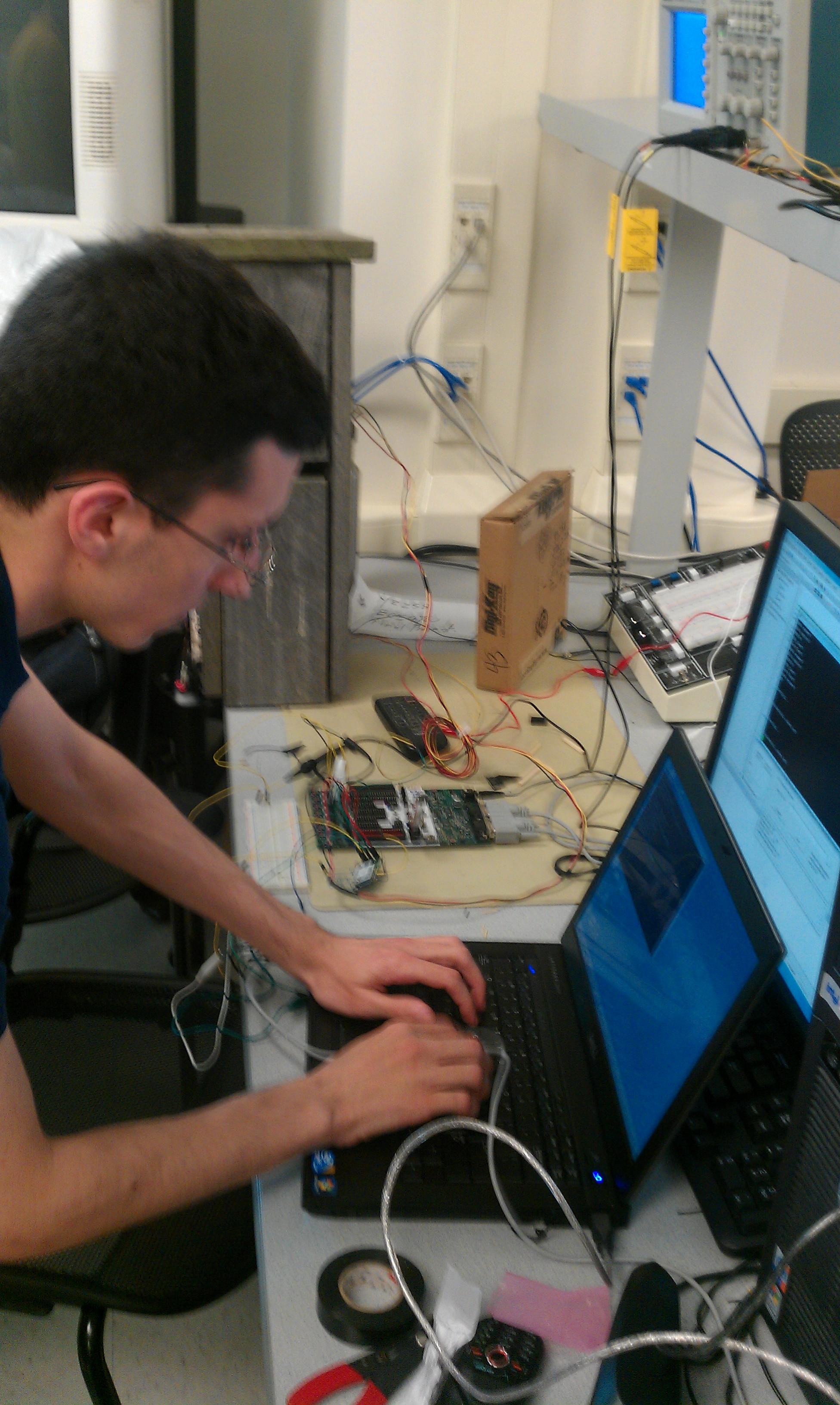
Jeff makes sure the server is up and running.
|
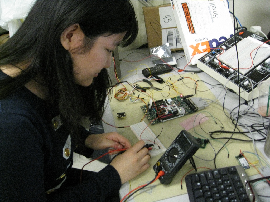
Cindy checks that a circuit is correctly built.
|
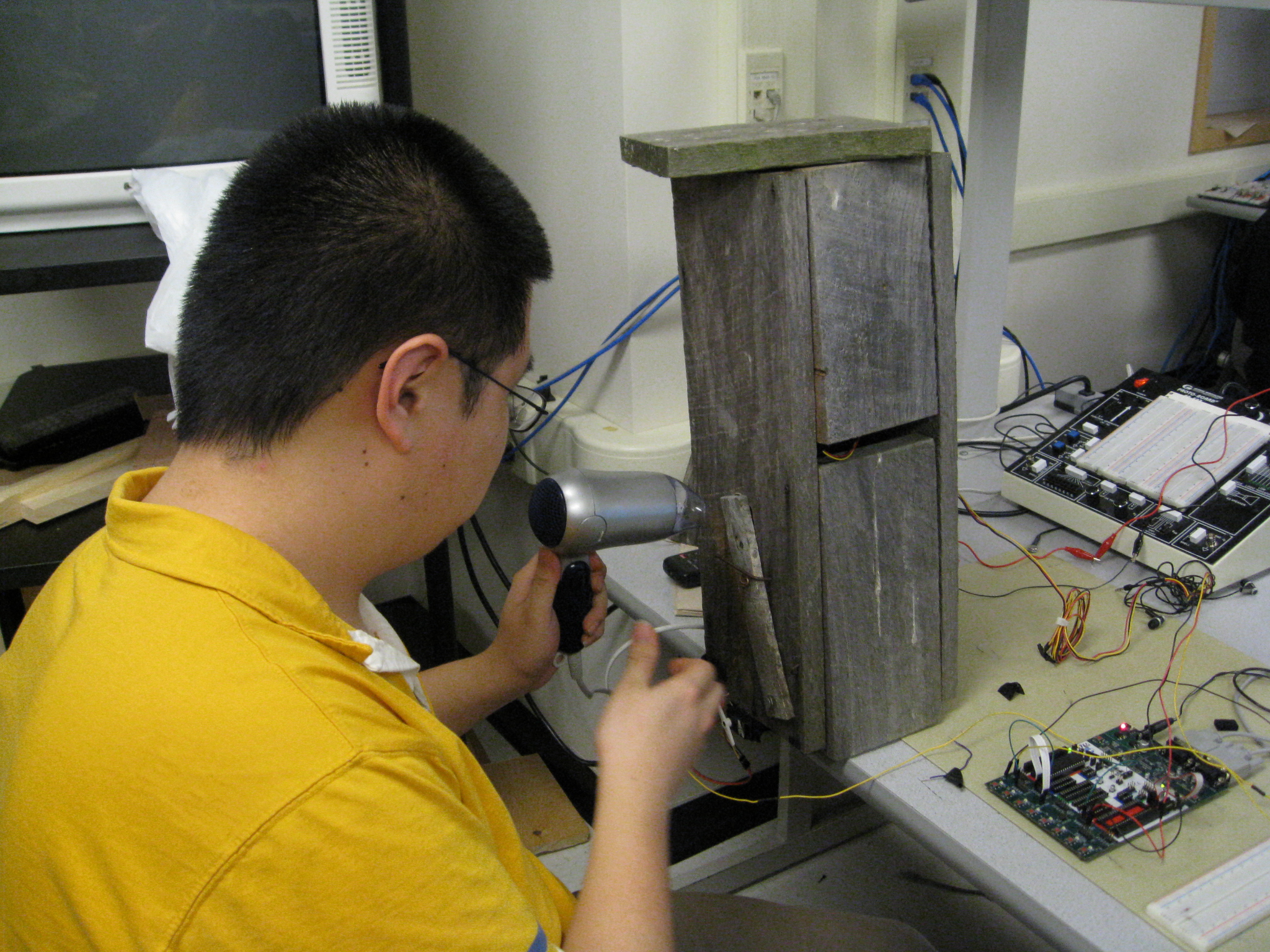
Ian tests the system by triggering the PIR sensor with a hair dryer.
|
References
Datasheets
RN-134 Datasheet
RN-134 User Manual & Reference
STK-500 User Guide
Parallax PIR Sensor Datasheet
Maxx 400 Reference
Vendor sites
Digi-Key
Jameco
Code/designs borrowed from others
Useful LAMP/PHP tutorial (see Conclusions section regarding this citation)
Useful software
AVR Studio
Diagram Designer
ExpressPCB Schematic Software
|