Motivation
A breaker-level power metering device for measuring energy on 4 different circuit lines and wirelessly outputting that energy data onto Google PowerMeter.
Useful Links
Similar Projects
The fastest, cheapest way to slow climate change is to USE LESS ENERGY. According to a recent National Geographic article, most of us could reduce the amount of energy we consume by about 25 percent. So why isn't everyone doing this?
There is a growing group of Zigbee devices targeted at residential and commercial energy consumers that monitor, control, and automate the delivery and use of energy. The novelty of these Smart Energy (SE) compliant devices is that they can form a dynamic device network regardless of the product manufacture because they use the same SE firmware load on Zigbee devices.
Our project aim was to create a breaker-level power metering device that would sit next to the home's main distribution panel (or subpanel) and measure the power on up to 4 different circuit lines and output the energy data to Google PowerMeter. The current is measured in a non-contact manner so that any user could safely install the current sensors. The radio devices transmitting the power data comply with the ISM 2.4 GHz frequency band standards and also implement a Zigbee defined encryption for security.
We suspect that our version of the XBee SE Power Meter would be extremely useful for landlords and small businesses looking for a low cost way of monitoring multiple buildings or renting out portions of the same home. In the past, this group has largely been delayed in becoming energy conscious because they have almost no motivation to buy high efficiency windows or appliances as the tenants pay the energy bills. Equally unmotivated are the tenants, who are frequently short term occupants, and don't want to invest in the building either. Our system makes it easy and cheap for the commercial building owner to monitor the energy usage which helps with maintenance and is a selling point for the tenants if a public website is used.
System
Top Level Diagram
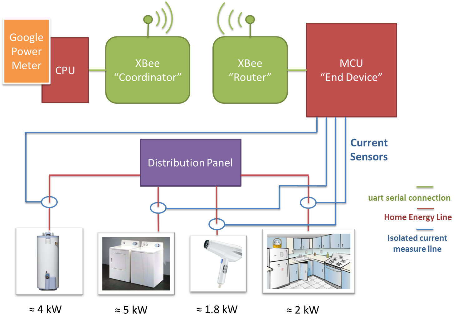
In the diagram above, we see the end-to-end top level description of the system. The process is managed with a Python program on the computer that controls the "Coordinator" XBee device and periodically provides the Google PowerMeter system with the cumulative kilowatt-hour energy readings from each of the measured circuits.
The terms "Coordinator" and "Router" refer to the specific XBee SE firmware that is loaded onto the XBee. A "Coordinator" controls how "Routers" connect to the Zigbee network among other network privileges and also may transmit, receive, or route data. A "Router" must first ask the "Coordinator" to join the Zigbee network, but after that it gains network management privileges and may transmit, receive, or route data. Hopefully it is obvious at this point that the variety of Zigbee device types and their common network privileges make for a very flexible and dynamic network.
For one measure process, the CPU sends the XBee "Coordinator" an SE formatted API frame that asks the "Router" to poll the end devices attached to it. This frame structure is not subtle as it is the backbone of the SE compliance, see the section of XBee and SE for more information. The "Router" receives this API framed command and forwards it to the "end device" that is attached to it: the MCU. The MCU must parse the API frame and return the measured power values in the same API framed structure. The power values are constantly being measured by the MCU and so the value it sends to the router is an accumulated power value for each of the circuits it's measuring. These values are returned to the "Coordinator" and sent over serial to the Python program on the CPU which puts them to Google PowerMeter.
XBee and Smart Energy
Initializing the Devices
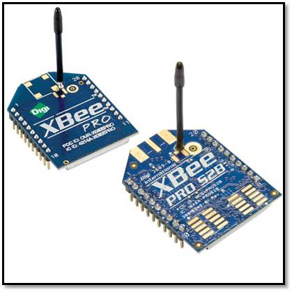
The purchased XBee RF modules we purchased arrived in a raw state in that they we're not yet configured with the firmware needed to operate as different devices within an SE network.
In order to change the firmware we had to download and learn digi's X-CTU. This software is designed to interact with the firmware files on the XBee's and was essential in first establishing a network.
We first established the serial connection to the modules by using the AT commands over serial within X-CTU. This 'AT' setup is a workable sort of command line for the devices in which you can read and write the parameters using short ASCII codes. This allowed us to read the errors off the devices as we tried to establish a connection between them.
We got comfortable with the 'AT' commands, established the connection with X-CTU, and determined the state of both devices before loading on the SE firmware. The firmware is relatively simple to load once you established the connection with X-CTU. One issue is that once you've loaded the SE device firmware the modules will only communicate in API mode and so debugging on the serial line becomes non-trivial. Once in API mode, we relied on the LED toggle pattern to understand device state and network status. XBee offers three device types to be loaded onto the modules: Coordinator, Router, and Device. Since we only had two devices it was simplest to use one Coordinator and one Router. Below are the abridged behaviors for the two device types we used.
- Coordinator -
The coordinator is configured to start a network on one of the 14 channels in the default scan channels list. We don't choose the channel, it just searches for the one with minimal conflict will occur. Once a network channel has been chosen, a modem status API frame is sent across UART and the LED will toggle at 1Hz. We ran into problems at first connecting to this established network because the Permit-joining time had the incorrect default value and was not allowing the router enough time to join. It should also be noted that the encryption link key is also set and distributed by the coordinator module.
- Router -
The router is configured to join any network that allows joining up to three times when first powered on. This is very handy for debugging in that you can rapidly test network connecting by simply power cycling the router (the coordinator is never powered down). Once a network is found, the router will request the encryption link key from the coordinator. When a router is connected to a network is sends an confirmation API frame through its UART and blinks its LED at 2Hz.
Implementing ZigBee Device Profile (ZDP)
The Zigbee Device Profile is the communication protocol over which you manage the devices in your network. In order for our system to be Zigbee Smart Energy compliant we were required to code a significant portion of the feature list in the ZDP. The challenge with implementing the ZDP in Python was correctly formatting the transmitted API frames and parsing the returned API frames on UART. We coded the parsing and formatting for the following XBee ZDP messages:
- Simple Descriptor Request
- Active Endpoints Request
- Match Descriptor Request
- Unsupported ZPD requests
A more detailed discussion of packaging and parsing the API frames follows the next section.
Zigbee Cluster Library (ZCL) Support
The Zigbee Cluster Library specification is the means by which we communicate commands to the coordinator which in turn commands the router. The library is broken up into clusters depending on the specific functionality. We implemented the Basic Cluster set (Cluster ID 0x0000) and the Simple Metering Cluster (Cluster ID 0x0702) so that we would conform the Zigbee required cluster support for a metering device. The list of general features that Zigbee requires of a metering device are as follows:
| - Key Establishment | ||
| - Join (end devices and routers only) | ||
| - Form Network (coordinator only) | ||
| - Restore to Factory Fresh Settings | ||
| - Bind Manager - (coordinator only) | ||
| - Allow Smart Energy devices to join the Network | ||
| - ZDP Bind Response | ||
| - ZDP Unbind Response | ||
| - End Device Announce | ||
| - Service Discovery response |
We also had to make sure the following values were returned if prompted.
| Name | Value |
| Device ID | 0x0501 |
| Basic (server) | 0x0000 |
| Simple Metering (server) | |
| Metering Server:Reading Info Set: CurrentSummationDelivered | 0x0000 |
| Metering Server: Meter Status Set: Status | 0x0200 |
| Metering Server: Formatting Attribute Set: UnitofMeasure | 0x0300 |
| Metering Server: Formatting Attribute Set: SummationFormatting | 0x0303 |
| Metering Server: Formatting Attribute Set: MeteringDeviceType | 0x0306 |
We used the Explicit API frames (0x11 and 0x91) to send and receive the smart energy messages.
Smart Energy Profile Security
To be part of a Smart Energy network, our device had to use one of the Zigbee specified methods for establishing network link keys. We chose to implement the Joining with Preinstalled Trust Center Link Keys option. It was specifically required that our Simple Metering device be able to identify the Application Link Key as that key was the one utilized for our cluster.
Constructing/Parsing API Frames
The following table is the spec to which we code all our API frames, from the CPU and MCU.
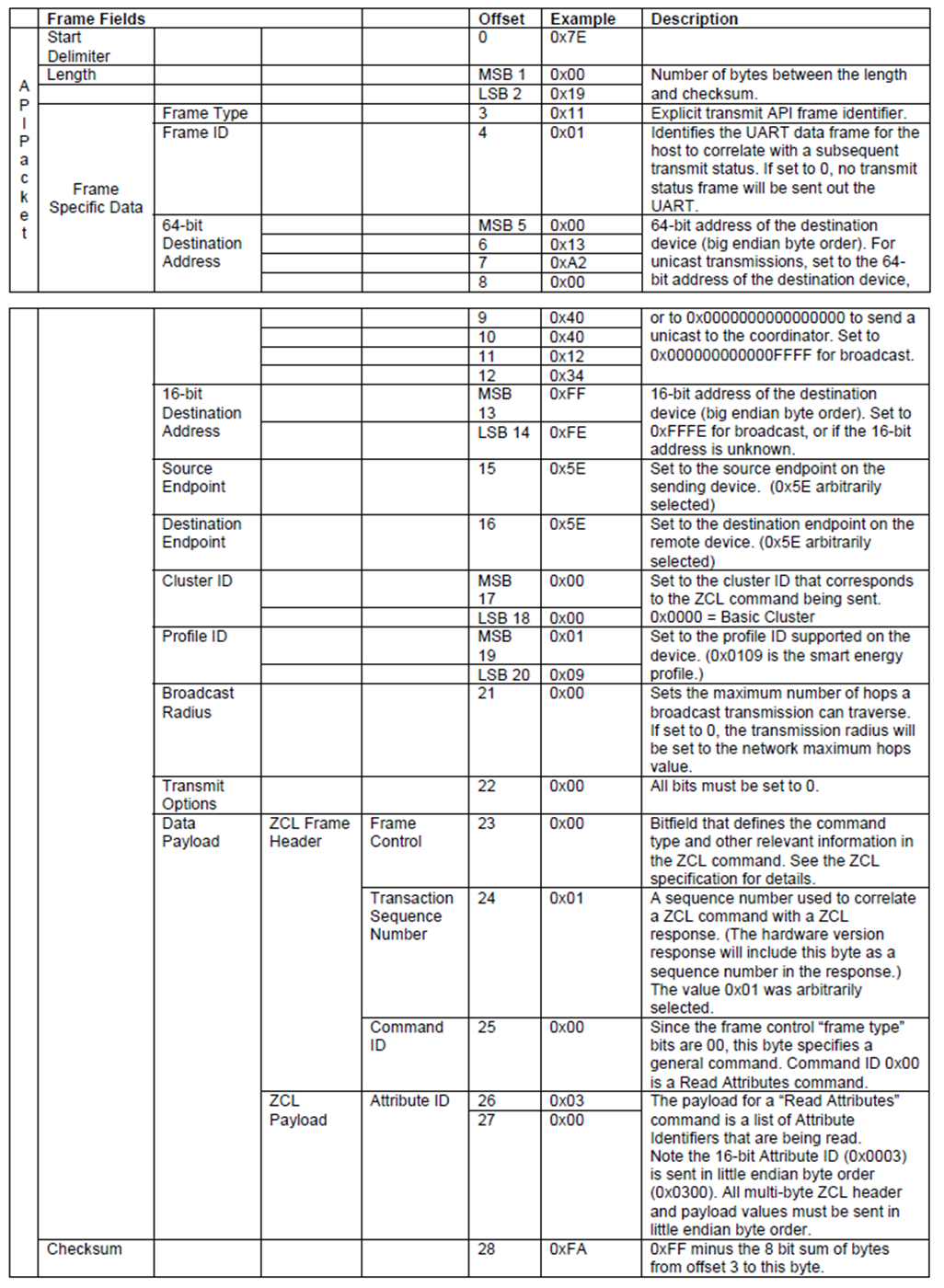
The CPU truly implements the full table, while the MCU has zero values for much of the table. For example, when polled by the router for an accumulated power value the MCU will read the first two values of the frame, the start delimiter (0x7E) and the length (usually around 0x21). Then the MCU will begin to parse through until it finds the Cluster ID 0x0702 and Profile ID before it decides what to send back to the router. When it send a frame back to the router it will package the frame in the same way except it will fill the data payload with the requested power meter measure.
Software
CPU Python Program
The radio connected to the CPU acts as the ZigBee Coordinator for the network, and periodically polls the power meter for usage data. We implemented a large portion of the ZigBee and Smart Energy stacks in Python, and implemented both the Simple Metering and Coordinator functionality, so the computer drove both radios. This allowed us to test the XBee API and ZigBee stack code before translating it to the microcontroller. Being able to reliably control the radios from the computer made debugging the microcontroller code far simpler than it otherwise would have been.
The Python program provides an extensible object-oriented library for implementing ZigBee devices on XBee radios. The library has three layers: A serial XBee API interface, a ZigBee Device Objects layer, and a ZigBee Cluster Library layer.
The XBee API interface provides an easy way to send and receive messages over a serial connection to the radio. It depends on PySerial, a free library for serial communication from Python. The API interface features a SerialConnection object that can send and receive messages asynchronously, dispatch received messages to custom handlers, and block after sending a message until a reply is received from the XBee. API messages are translated to and from Python objects so that forming messages is done by creating an object with appropriate parameters, and interpreting received messages requires reading values from an object's accessor methods.
All ZigBee messages come from the radio as ZigBee Explicit Rx frames. A ZigBeeDevice class parses these messages to find what ZigBee command they contain, and reply appropriately. ZigBee requires that all devices respond to a set of ZigBee Device Objects (ZDO) commands, and ZigBee Smart Energy specifies sets ZigBee Cluster Library (ZCL) commands and variables that a device must provide. The Python code provides a framework for handling all these requests, but only the required ZDO commands are fully implemented.
Google PowerMeter Operation
Google PowerMeter is an online application for recording, viewing, and analyzing power usage data. Google provides a public API for submitting data to PowerMeter, with C and Python interfaces. The Python interface makes it easy for us to upload data to Google. PowerMeter can track multiple variables for each user, so we can use it to track each of our meter's four channels separately.
MCU Metering Operation
Our MCU is acting as the end device in the system in that it accumulates the power values for when the router asks for them. It operates such that ISR on compare for Timer 0 is thrown every 2ms. With that ISR we place a counter such that we start an A to D conversion process every 1/50 of a second. This conversion process maps the input voltage (which is 0 to 3.3) to a char value of 0 to 255. Our Hall-effect sensors output a sin wave with a mean value of 2.5V, and amplitude proportional to the current being measured. To measure the amplitude, we keep the last ten measurements in a ring buffer, and choose the maximum measurement of the last ten. From the max, we subtract the mean (to eliminate the DC offset of the wave) and multiply by a constant factor to find the current, in amperes. To integrate, we multiply this value by 120V times 20 ms, for a measurement in watt-milliseconds. The data is stored as watt-milliseconds on the microcontroller, and scaled by the computer to kWh.
Hardware
Model Distribution Panel
In order to test our machine in a safe environment we opted to build a smaller version of a home distribution panel. Below is a diagram of our mock distribution panel. Though it is not shown in the diagram, on half of the current sensed lines we pass them through the current sensor twice in order to increase the sensitivity.
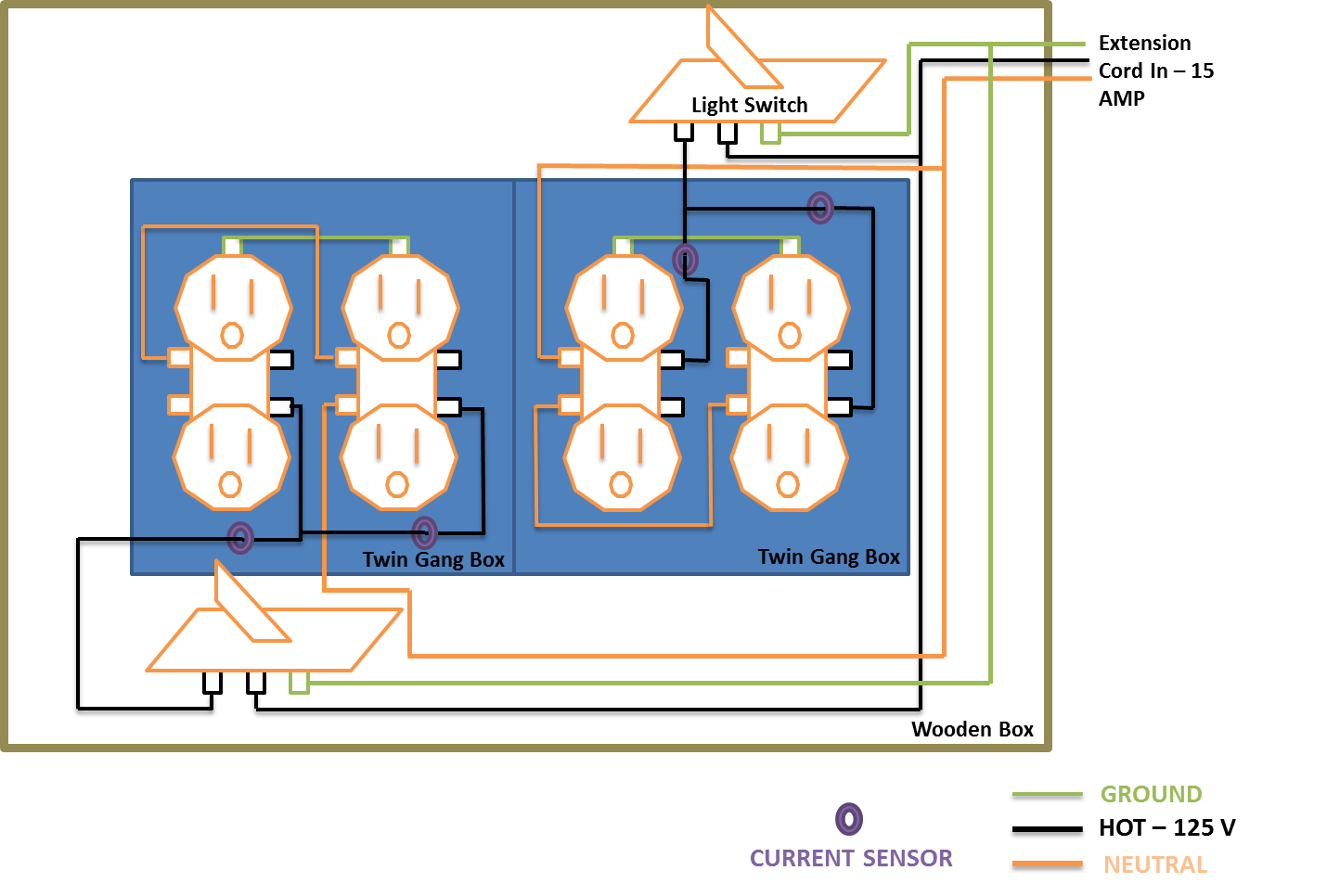
The extension cord from the box plugs into a typical wall outlet (rated to 15 A) through a Kill-A-Watt meter. We use the Kill-A-Watt meter to get a reliable measure of the power for which to calibrate our meter. The mock distribution panel above operates on lower power numbers than the high power draw portions of the house (dryer, water heater, etc), but it's strictly for demo purposes. The current sensors we used are rated to 80A on the through line, so our system will work for in-home or small business power metering. It was unrealistic to try to demo on those larger numbers. Although we suspect it will work for larger current loads, we do not intend to try it on any higher loads than on our mock distribution panel.
Hall Effect Current Sensors
DeviceCraft Hall Effect Isolated Current Sensor - P/N IS-2-80A 80amps
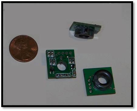
We chose to use Hall Effect Isolated Current Sensors through careful consideration of other options. We only considered non-contact sensors in order to provide a degree of safety for ourselves and also to isolate the large voltages from the microcontroller and XBees. In other projects the current sensing devices tend to be current transforms of some kind. The magnetic cores to these devices make them more expensive than the Hall Effect Sensors we chose.
We chose to use the 80 A rated devices because that brought our system to a 10 kW max rating on any one channel. It was important to us that even though we were demoing on 15 A, we would make a practical system that was as close to the a market available Smart Meter as possible. For this reason we wanted to make sure that the high power domestic water heaters (typically the largest energy draw in the house) were well under our max rating. Since typical water heaters range from 4 to about 7kW we're covered. We also found that the sensor's sensitivity rating of approximately 23 mV/A gave us a broad range of power values that we could measure. For instance, the low end of our scale is to measure 1/2 A (by passing the wire through the sensor twice) or about 60W minimum, which is about right for a threshold since that's around the power value of lights around the house.
A drawback of the Hall Effect sensors is that the user must feed the wire through the sensor instead of clamping around the wire as is possible with split core transformers (which are much more expensive). This is slightly more dangerous as it requires the user to throw the main bus breaker in the distribution in order to install the system.
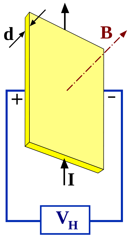
- Hall Effect Sensor Theory - Honeywell.com Explanation
Given a magnetic field B which is coming from the wires we're trying to measure current off of, we can get a measure of the strength of that magnetic field if we impose a small amount of current I on a conducting plate perpendicular to the direction of the magnetic field. In the diagram above, the electrons flow from the top edge of the plate to the bottom edge of the plate. By the right hand rule, those electrons will be pushed towards the edge with a + sign on it and will move in curled paths. The average deflection of the current generates a potential different between the edges of the plate (+ and - edges in the diagram). The diagram is slightly confusing, but the voltage lines are connected to the thin edges of the plate.
Atmel Mega 644 w/ ECE 4760 Prototype Board
We used the standard ECE 4760 prototype board with a custom-built 3.3V regulator. Since the XBee radios require a 3.3V power source, we decided to run the microcontroller on 3.3V as well, so we could set up serial communication easily.
Serial Communications Board
So that the XBee coordinator could talk to the computer, we built a simple RS-232 board, and then connect it to the computer with a USB-to-RS-232 cable.
Results
Meter Accuracy / Speed
We were able to measure current with a resolution of about 1/3 amp. We integrated from current to calculate power consumption, sampling at 12.5 Hz. Google PowerMeter only allows one data upload every ten minutes, so our program reported the total consumption to the terminal at a higher frequency so that changes could be seen instantly.
Usability
One of the key features of our project is the usability. The radios take care of all the networking tasks without input from the user. Once connected, the system is self sustained and Google PowerMeter provides a convenient place to check your power usage like you would check your email.
Interference with Other Groups
Our radios implement a security encryption layer so we are not affected by other groups. Our radios also conform to the ISM 2.4 GHz standard, a portion of which states that the radios may not create harmful interference. We conform to that standard.
Safety in Operation and Construction
As mentioned in the hardware section, we chose non-contact current sensors with safety in mind. If our system were used a practical home monitoring scenario, the user should open the main bus to the distribution panel so that they can handle the lines without worry of electric shock. In constructing our model distribution panel I made efforts to consult online experts, the onsite electrical expert at Lowes, Professor Land, and all my wiring was double checked before I ever plugged anything in. This was probably overkill since it was a relatively simple circuit and our sensors were so well isolated, but it's good practice all the same.
Conclusions
Met Expectations ?
Our expectations were to build a power meter that would comply to the Smart Energy protocol. It would have been nice to get to a level where we could apply for Smart Energy Certification, but that was an unreasonable task. We were disappointed that our system did not work end-to-end, but think that it is quite close to working properly, and are happy with what we've accomplished so far. We hope that we can complete it in the next couple of weeks.
Conformation to Standards
We work within the Smart Energy standard, but have not achieved full compliance. As mentioned above, the Zigbee radios are certified for remote and base radio applications. Since our system is not portable, we do not require that our modules SAR testing. As stated in the Agency certifications for the Zigbees: we comply with the limits for a Class B digital device pursuant to part 15 of the FCC Rules. These limit are designed to provide reasonable protection against harmful interference in a residential installation.
IP Considerations
As far as we know, we have no IP issues to declare. We didn't not consult any other group in writing our Zigbee interface... we just used the various Zigbee spec sheets.
Ethical Considerations
One ethical consideration that Zigbee seems to have thought of is the possibility of one's energy usage being available on a public network. The devices implement an encryption so this is a non-issue.
Legal Considerations
Don't think that's applicable.
Appendix
Python Code
MCU Code
Google PowerMeter Code
Budget
| Quantity | Part Description | Vendor / Part ID | Price |
|---|---|---|---|
| 1 | ECE 4760 Custom PC board | Course | $4 |
| 1 | Custom PC Board - RS232 & Max233 | Course | $8 |
| 1 | Mega644 | Course | $8 |
| 1 | DIP Socket | Course | $1 |
| 1 | Solder Board (larger) | Course | $2.50 |
| 1 | White Board | Course | $6 |
| 4 | Hall Effect Current Sensors | DeviceCraft / IS-2-80A | $6.50 |
| 2 | XBee RF ZB | Digi / XB24-Z7CIT-004 | $17 |
| TOTAL | 89.5 | ||
Division of Labor
Model Distribution Panel - Adam
Initial Zigbee Setup and Testing - Ken and Adam
Online Google PowerMeter Script
- Ken
Custom Board Population and Testing
- AdamPython Zigbee Software Interface - Ken
Testing and Final Integration of Zigbees - Ken
Current Sensor Testing - Adam
MCU End Device Program - Ken and Adam
Web Page Construction - Ken and Adam
Data Sheets
Zigbee Reference Documents
- Using XBee Smart Energy
- XBee SE Manual
- ZigBee Cluster Library
- Zigbee Smart Energy Profile Spec
- Zigbee Spec
Thanks To
We'd like to thank Dr. Bruce Land for his efforts in helping to debug our system and for basically teaching us everything we know about microcontrollers. We'd also like to thank Samtec for their generosity in sampling the necessary pin adapters for the XBees connections.