A Keyboard Synthesizer Workstation
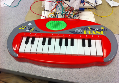
Our Keyboard Synthesizer project aims to create a multi-instrument keyboard that can record several different synthesized instruments and play back the track simultaneously. We took a children’s toy keyboard and adapted the printed circuit board within to play a range of notes from various musical instruments. Our user interface is a phone-style keypad for command input along with an LCD that displays the various modes/operations the keyboard supports. It lets the user knows what each key on the keypad does through a help mode and allows for the user to do any of the following: switch the current instrument between a piano, drum, guitar, and clarinet; record a track with that instrument; playback a specific track or all of the tracks layered together; play a demo song; and delete a specific track or all tracks. With these basic operations, the keyboard and keypad combination allow a user to play a variety of notes on a variety of instruments and hear them all played back layered on top of each other.
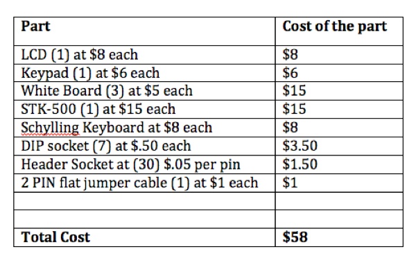
A high-end keyboard synthesizer may cost around $3,000. In this project, we aim to create a very basic keyboard with analogous functionality for less than $75 dollars. Obviously, the quality of the sounds, number of instruments one can play, playback length, and lots of other features are going to be inferior or unimplemented. However, it will still be impressive (and fun!) for us to create a functional keyboard for such little cost in such little time.

Basic Info
For our senior-year design project, we built a basic synthesizer workstation using an Mega644 microcontroller on an STK-500 board, using frequency modulation and additive synthesis to play/record 4 different instruments on to 4 separate tracks.
Matt Ferrari mjf259
Alec Hollingsworth arh68
/* ECE 4760 Final Project
*
* Matt Ferrari mjf259
* Alec Hollingsworth arh68
*/
#include "trtSettings.h"
#include "trtkernel644.c"
#include <util/delay.h>
#include <stdio.h>
#include <math.h>
#include <string.h>
// serial communication library
// Don't mess with the semaphores
#define SEM_RX_ISR_SIGNAL 1
#define SEM_STRING_DONE 2 // user hit <enter>
#include "trtUart.h"
#include "trtUart.c"
#include "lcd_lib.h"
unsigned int args[4];
const int8_t LCD_initialize[] = " ";
int8_t lcd_buffer1[17];// LCD display buffer
int8_t lcd_buffer2[17];// LCD display buffer
// UART file descriptor
// putchar and getchar are in uart.c
FILE uart_str = FDEV_SETUP_STREAM(uart_putchar, uart_getchar, _FDEV_SETUP_RW);
// allow task2 to control task1
#define SEM_TASK1_WAIT 3
// two semaphores to protect message --
// sender must wait until message is received
// -- init to 1 becuase don't need to wait for first message
// receiver must wait until message is sent
#define SEM_TX_WAIT 4
#define SEM_RX_WAIT 5
#define SEM_BEAT 7 // semaphore to protect shared variable
#define maxkeys 16
#define PORTDIR DDRB
#define PORTDATA PORTB
#define PORTIN PINB
#define PORTDIR2 DDRC
#define PORTDATA2 PORTC
#define PORTIN2 PINC
#define NoPush 1
#define MaybePush 2
#define Pushed 3
#define MaybeNoPush 4
#define READ(U, N) ((U) >> (N) & 1u)
#define SET(U, N) ((void)((U) |= 1u << (N)))
#define CLR(U, N) ((void)((U) &= ~(1u << (N))))
#define FLIP(U, N) ((void)((U) ^= 1u << (N)))
#define SONG_LENGTH 128 //8 beats/sec * 16 seconds
// Macros for the State Machine table. This helps reduce boilerplate code
// and increases readability
#define OUTPUT(MESSAGE)\
fprintf(stdout, MESSAGE);
#define STATE_TRANSITION(KEYNUMBER,STATE,MESSAGE1,MESSAGE2,NEWSTATE,FUNCTION) \
if (key == KEYNUMBER && current_state == STATE) {\
sprintf((char *) lcd_buffer1,MESSAGE1);\
sprintf((char *) lcd_buffer2,MESSAGE2);\
fprintf(stdout, (char *) lcd_buffer1);\
fprintf(stdout, (char *) lcd_buffer2);\
current_state = NEWSTATE;\
FUNCTION;\
return;\
}
//key pad scan table for the command pad
unsigned char keytbl[16]=
{0xee, 0xed, 0xeb, 0xe7,
0xde, 0xdd, 0xdb, 0xd7,
0xbe, 0xbd, 0xbb, 0xb7,
0x7e, 0x7d, 0x7b, 0x77};
//piano scan table that contains expected encoder outputs
uint16_t pianotbl[23]=
{(255 << 8) | 12,
(254 << 8) | 12,
(247 << 8) | 12,
(246 << 8) | 12,
(191 << 8) | 12,
(190 << 8) | 12,
(183 << 8) | 12,
(182 << 8) | 12,
(255 << 8) | 20,
(253 << 8) | 20,
(239 << 8) | 20,
(237 << 8) | 20,
(127 << 8) | 20,
(125 << 8) | 20,
(111 << 8) | 20,
(109 << 8) | 20,
(255 << 8) | 36,
(251 << 8) | 36,
(223 << 8) | 36,
(219 << 8) | 36,
(255 << 8) | 32,
(251 << 8) | 32,
(223 << 8) | 32,
};
//frequencies of notes for keyboard
//8.388608 is derived from the PWM rate. A 1Hz signal would need
// an increment of 8.388608.
uint16_t note_accs[] = {
(uint16_t) ( 8.388608 * 932.328 ),
(uint16_t) ( 8.388608 * 880.000 ),
(uint16_t) ( 8.388608 * 830.609 ),
(uint16_t) ( 8.388608 * 783.991 ),
(uint16_t) ( 8.388608 * 739.989 ),
(uint16_t) ( 8.388608 * 698.456 ),
(uint16_t) ( 8.388608 * 659.255 ),
(uint16_t) ( 8.388608 * 622.254 ),
(uint16_t) ( 8.388608 * 587.330 ),
(uint16_t) ( 8.388608 * 554.365 ),
(uint16_t) ( 8.388608 * 523.251 ),
(uint16_t) ( 8.388608 * 493.883 ),
(uint16_t) ( 8.388608 * 466.164 ),
(uint16_t) ( 8.388608 * 440.000 ),
(uint16_t) ( 8.388608 * 415.305 ),
(uint16_t) ( 8.388608 * 391.995 ),
(uint16_t) ( 8.388608 * 369.994 ),
(uint16_t) ( 8.388608 * 349.228 ),
(uint16_t) ( 8.388608 * 329.628 ),
(uint16_t) ( 8.388608 * 311.127 ),
(uint16_t) ( 8.388608 * 293.665 ),
(uint16_t) ( 8.388608 * 277.183 ),
(uint16_t) ( 8.388608 * 261.626 ),
};
// States the controller can take
typedef enum {
Normal_State,
Help_State,
Playback_State,
Recording_State
} State;
State current_state = Normal_State; // start off in normal mode
unsigned char nand_reading1;
unsigned char nand_reading2;
unsigned char cur_command_key ;
unsigned char last_command_key ;
unsigned char cur_piano_key ;
unsigned char last_piano_key ;
unsigned char sineTable[256]; // the various wave tables for our sounds. We
unsigned char sineTable2[256]; // record 256 samples of 1 full cycle
unsigned char sineTable3[256];
unsigned char sineTable4[256];
unsigned char song[4][SONG_LENGTH]; // the recorded note data
unsigned char *song_table[4]; // table to look up what wavetable a given
// instrument uses
uint8_t cur_song = 0;
unsigned char interrupt_beat_task = 0;
unsigned char PushState;
unsigned char play_current_track_only = 0;
unsigned long beat_debug = 0;
unsigned long cur_beat = 0;
uint16_t acc[4]; // accumulators and increments for the PWM output
uint16_t inc[4];
char envelope[256]; // envelope to control how the amplitude attacks, decays
uint8_t e[4]; // envelope indices
char e2[4];
void nop()
{
;
}
void update_track(int new_track)
{
cur_song = new_track;
}
void erase_track()
{
int i;
//clear the track
for(i=0;i<SONG_LENGTH;i++) {
song[cur_song][i]=0;
}
}
void play_song()
{
play_current_track_only = 0;
//signal the beat task
trtSignal(SEM_BEAT);
}
void play_track()
{
play_current_track_only = 1;
//signal the beat task
trtSignal(SEM_BEAT);
}
void record()
{
int i;
//clear the track
for(i=0;i<SONG_LENGTH;i++) {
song[cur_song][i] = 0;
}
//signal the beat task
trtSignal(SEM_BEAT);
}
void escape()
{
//stops current action
interrupt_beat_task = 1;
}
void update_instr(unsigned char *newtable)
{
song_table[cur_song] = newtable;
}
void erase_tracks()
{
int i,j;
//clear current song
for(j=0;j<4;j++) {
for(i=0;i<SONG_LENGTH;i++) {
song[j][i] = 0;
}
}
}
void handle_keypress(int key)
{
//handles keypad presses
//messages are printed to the LCD
//updates the state and carries out functions
STATE_TRANSITION( 0,Normal_State,"Instrument is ","now Xylophone ",Normal_State,update_instr(sineTable));
STATE_TRANSITION( 1,Normal_State,"Instrument is ","now Brass ",Normal_State,update_instr(sineTable2));
STATE_TRANSITION( 2,Normal_State,"Instrument is ","now Robot Sound ",Normal_State,update_instr(sineTable3));
STATE_TRANSITION( 3,Normal_State,"Instrument is ","now Video Game ",Normal_State,update_instr(sineTable4));
STATE_TRANSITION( 4,Normal_State,"Current Track: 1"," ",Normal_State,update_track(0));
STATE_TRANSITION( 5,Normal_State,"Current Track: 2"," ",Normal_State,update_track(1));
STATE_TRANSITION( 6,Normal_State,"Current Track: 3"," ",Normal_State,update_track(2));
STATE_TRANSITION( 7,Normal_State,"Current Track: 4"," ",Normal_State,update_track(3));
STATE_TRANSITION( 8,Normal_State,"Track erased "," ",Normal_State,erase_track());
STATE_TRANSITION( 9,Normal_State,"Action stopped "," ",Normal_State,nop());
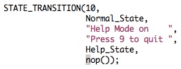
STATE_TRANSITION(10,Normal_State,"Help Mode on ","Press 9 to quit ",Help_State,nop());
STATE_TRANSITION(12,Normal_State,"Recording to the","selected track ",Recording_State,record());
STATE_TRANSITION(13,Normal_State,"Playing back the","selected track ",Playback_State,play_track());
STATE_TRANSITION(14,Normal_State,"Playing back ","all tracks ",Playback_State,play_song());
STATE_TRANSITION(15,Normal_State,"All tracks ","deleted ",Normal_State,erase_tracks());
//help state - displays on LCD what each key yields
STATE_TRANSITION( 0, Help_State,"Make instrument ","Xylophone ",Help_State,nop());
STATE_TRANSITION( 1, Help_State,"Make instrument ","Brass ",Help_State,nop());
STATE_TRANSITION( 2, Help_State,"Make instrument ","Robot Sound ",Help_State,nop());
STATE_TRANSITION( 3, Help_State,"Make instrument ","Video Game ",Help_State,nop());
STATE_TRANSITION( 4, Help_State,"Selects track 1 "," ",Help_State,nop());
STATE_TRANSITION( 5, Help_State,"Selects track 2 "," ",Help_State,nop());
STATE_TRANSITION( 6, Help_State,"Selects track 3 "," ",Help_State,nop());
STATE_TRANSITION( 7, Help_State,"Selects track 4 "," ",Help_State,nop());
STATE_TRANSITION( 8, Help_State,"Erases the ","selected track ",Help_State,nop());
STATE_TRANSITION( 9, Help_State,"Stops recording ","or playback ",Help_State,nop());
STATE_TRANSITION(10, Help_State,"Help mode off "," ",Normal_State,nop());
STATE_TRANSITION(11, Help_State,"The answer to ","life is 42 ",Help_State,nop());
STATE_TRANSITION(12, Help_State,"Start recording ","to chosen track ",Help_State,nop());
STATE_TRANSITION(13, Help_State,"Plays back the ","selected track ",Help_State,nop());
STATE_TRANSITION(14, Help_State,"Plays back all ","tracks ",Help_State,nop());
STATE_TRANSITION(15, Help_State,"Deletes all of ","the tracks ",Help_State,nop());
//playback state
STATE_TRANSITION( 9,Playback_State,"Action stopped "," ",Normal_State,escape());
// recording state
STATE_TRANSITION( 9,Recording_State,"Action stopped "," ",Normal_State,escape());
}
ISR (TIMER0_OVF_vect) // fires every 128us
{
//calculate next sample's index
acc[0] += inc[0] ;
acc[1] += inc[1] ;
acc[2] += inc[2] ;
acc[3] += inc[3] ;
if (current_state == Normal_State || current_state == Recording_State) {
//ramped up sum of sine waves
OCR2A = 128 + ((((int8_t) song_table[cur_song][acc[cur_song] >> 8]) * envelope[e[cur_song]]) >> 8 >> 2);
} else if (current_state == Playback_State) {
if (play_current_track_only) {
OCR2A = 128 + ((((int8_t) song_table[cur_song][acc[cur_song] >> 8]) * envelope[e[cur_song]]) >> 8 >> 2);
} else {
OCR2A = 128 + (((int16_t) ((((int8_t) song_table[0][acc[0] >> 8]) * envelope[e[0]]) >> 8)
+ (int16_t) ((((int8_t) song_table[1][acc[1] >> 8]) * envelope[e[1]]) >> 8)
+ (int16_t) ((((int8_t) song_table[2][acc[2] >> 8]) * envelope[e[2]]) >> 8)
+ (int16_t) ((((int8_t) song_table[3][acc[3] >> 8]) * envelope[e[3]]) >> 8)
)>>2); // div by # of tracks = 4
}
}
// step to next envelope sample if we're playing/decaying a note
if (e[0] != 0 && e[0] != 255) { e2[0]++; if (e2[0] == 0) { e[0]++; } }
if (e[1] != 0 && e[1] != 255) { e2[1]++; if (e2[1] == 0) { e[1]++; } }
if (e[2] != 0 && e[2] != 255) { e2[2]++; if (e2[2] == 0) { e[2]++; } }
if (e[3] != 0 && e[3] != 255) { e2[3]++; if (e2[3] == 0) { e[3]++; } }
}
void handle_command_key()
{
handle_keypress(cur_command_key-1); // in state.c
}
void handle_piano_key()
{
if (current_state == Normal_State || current_state == Recording_State) {
// use current song variables
if (cur_piano_key != 0) { // got a note!
inc[cur_song] = note_accs[cur_piano_key-1];
e[cur_song] = 1;
} else { // got silence, reset envelope to beginning (silence)
e[cur_song] = 0;
}
} else if (current_state == Playback_State) {
; // ignore input when playing back
}
}
// unused task
void unused(void* args)
{
trtTerminate();
}
//read the matrix by alternating input/output between the rows and cols
void read_controlpad()
{
char key;
//get lower nibble
PORTDIR = 0x0f;
PORTDATA = 0xf0;
_delay_us(5);
key = PORTIN;
//get upper nibble
PORTDIR = 0xf0;
PORTDATA = 0x0f;
_delay_us(5);
key = key | PORTIN;
last_command_key = cur_command_key;
//find matching keycode in keytbl
if (key != 0xff) {
for (cur_command_key=0; cur_command_key<maxkeys; cur_command_key++) {
if (keytbl[cur_command_key]==key) {
break;
}
}
if (cur_command_key==maxkeys)
cur_command_key=0;
else cur_command_key++; //adjust by one to make range 1-16
}
else cur_command_key=0;
}
// examine the encoder outputs, scan through a table to find a match
// update cur_piano_key
void read_piano()
{
DDRC = 0; // all inputs
CLR(DDRD,DDD2);//set PIND2 to input
CLR(DDRD,DDD3);//set PIND3 to input
CLR(DDRD,DDD4);//set PIND4 to input
CLR(DDRD,DDD5);//set PIND5 to input
nand_reading1 = PINC;
nand_reading2 = 60 & PIND; //read pins D2,D3,D4,and D5 only
int i;
last_piano_key = cur_piano_key;
uint16_t val = ((nand_reading1 << 8) | nand_reading2);
for (i=0;i<23;i++) {
//decodes the keypress
if (val == pianotbl[i]) {
cur_piano_key = 24-(i+1);
return;
}
}
//no key was pressed
cur_piano_key = 0;
return;
}
void readKeypads(void* args)
{
uint32_t rel, dead ;
while(1)
{
read_controlpad();
read_piano();
//if a new key was pressed, decode it
if (last_command_key != cur_command_key)
handle_command_key();
//if a new key was pressed, decode it
if (last_piano_key != cur_piano_key)
handle_piano_key();
// Sleep - run every ~10ms
rel = trtCurrentTime() + SECONDS2TICKS(0.01);
dead = trtCurrentTime() + SECONDS2TICKS(0.02);
trtSleepUntil(rel, dead);
}
}
// This handles everything that needs to be done every beat (~.1s)
void beat_task(void* args)
{
uint32_t rel, dead ;
int i;
while(1)
{
trtWait(SEM_BEAT);
interrupt_beat_task = 0;
for(cur_beat=0;cur_beat<SONG_LENGTH && !interrupt_beat_task;cur_beat++)
{
if (current_state == Recording_State) {
song[cur_song][cur_beat] = cur_piano_key;
}
else if (current_state == Playback_State) {
for (i=0;i<4;i++) {
//get the ISR to play a note
if (song[i][cur_beat] == 0) {
e[i] = 0;
} else if (cur_beat > 0 && song[i][cur_beat-1] != song[i][cur_beat]) {
e[i] = 1;
inc[i] = note_accs[song[i][cur_beat]-1];
}
}
}
// Sleep
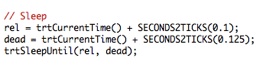
rel = trtCurrentTime() + SECONDS2TICKS(0.1);
dead = trtCurrentTime() + SECONDS2TICKS(0.125);
trtSleepUntil(rel, dead);
}
//done, silence and return to normal
e[0]=0;
e[1]=0;
e[2]=0;
e[3]=0;
current_state = Normal_State;
}
}
// another unused task
void print2(void* args)
{
trtTerminate();
}
// update the message display
void lcd_update(void* args)
{
uint32_t rel, dead ;
while(1)
{
LCDGotoXY(0, 0);
LCDstring((uint8_t*)lcd_buffer1, (uint8_t)strlen((char*)lcd_buffer1));
LCDGotoXY(0, 1);
LCDstring((uint8_t*)lcd_buffer2, (uint8_t)strlen((char*)lcd_buffer2));
// Sleep
rel = trtCurrentTime() + SECONDS2TICKS(0.1);
dead = trtCurrentTime() + SECONDS2TICKS(0.3);
trtSleepUntil(rel, dead);
}
}
//**********************************************************
// LCD setup
void init_lcd(void)
{
LCDinit();//initialize the display
LCDcursorOFF();
LCDclr();//clear the display
LCDGotoXY(0,0);
CopyStringtoLCD((const uint8_t *)LCD_initialize, 0, 0);
}
// --- Main Program ----------------------------------
int main(void)
{
int i,j;
//timer0 will regulate OCR2A
SET(TIMSK0, TOIE0); // overflow interrupt enable
SET(TCCR0B, CS01); // prescaler = 8
// timer2 is our PWM output
SET(TCCR2A, WGM20); // fast pwm mode
SET(TCCR2A, WGM21); // fast pwm mode
SET(TCCR2A, COM2A1); // clear oc0a on compare match,
// set oc0a at bottom (non-inverting)
SET(TCCR2B, CS20); // no prescaler
OCR2A = 128; // 'zero' the pwm output
SET(DDRD,DDD7); //PWM output on pin D.7
// create sine table and accumulators
// here we use additive synthesis and frequency modulation
for (i=0;i<256;i++) {
sineTable[i] = (char)(127*sin(6.283*i/256.0));
sineTable2[i] = (char)(( 127.*sin(6.283*i/256.0)
+ .45*127.*sin(6.283*i*2/256.0)
+ 127.*sin(6.283*i*3/256.0)
+ .41*127.*sin(6.283*i*4/256.0)
+ 127.*sin(6.283*.01*i/256.0))/3.86);
sineTable3[i] = (char)(127*sin(6.283*i/256.0 + 12*sin(6.283*2*i/256.0)));
sineTable4[i] = (char)(( 127.*sin(6.283*i/256.0)
+ .5*127.*sin(6.283*3*i/256.0)
+ .2*127.*sin(6.283*5*i/256.0)
+ 1.2*127.*sin(6.283*i*7/256.0))/2.9);
}
for (i=0;i<4;i++) { // for each song,
acc[i] = 0;
inc[i] = 0;
song_table[i] = sineTable; // songs start out as piano
for (j=0;j<SONG_LENGTH;j++) { // and nothing is recorded
song[i][j] = 0;
}
}
for(i=1;i<256;i++) {
if (1 <= i && i <= 4) envelope[i] = (char) (255./4*i);
if (5 <= i && i <= 10) envelope[i] = (char) (255);
if (11 <= i && i <= 255) envelope[i] = (char) (255.*121/(i*i));
}
envelope[0]=0; // first sample in envelope has to be 0 since
// we multiply against it for 'silence'
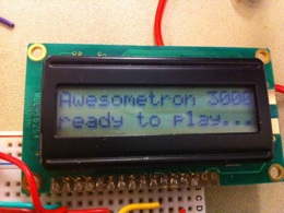
sprintf((char *) lcd_buffer1,"Awesometron 3000");
sprintf((char *) lcd_buffer2,"Press 9 for help");
init_lcd();
//init the UART -- trt_uart_init() is in trtUart.c
trt_uart_init();
stdout = stdin = stderr = &uart_str;
fprintf(stdout,"\n\r Starting... TRT 09feb09\n\r\n\r");
LCDclr();//clear the display
// start TRT
trtInitKernel(150); // 150 bytes for the idle task stack
// --- create semaphores ----------
// You must creat the first two semaphores if you use the uart
trtCreateSemaphore(SEM_RX_ISR_SIGNAL, 0) ; // uart receive ISR semaphore
trtCreateSemaphore(SEM_STRING_DONE,0) ; // user typed <enter>
// Task synch
trtCreateSemaphore(SEM_TASK1_WAIT, 0) ; // task2 controls task1 rate
// message protection
trtCreateSemaphore(SEM_TX_WAIT, 1) ; // message send interlock
trtCreateSemaphore(SEM_RX_WAIT, 0) ; // message receive interlock
// variable protection
trtCreateSemaphore(SEM_BEAT, 0) ; // protect shared variable
// --- creat tasks ----------------
trtCreateTask(unused, 100, SECONDS2TICKS(0.02), SECONDS2TICKS(0.04), &(args[0]));
trtCreateTask(readKeypads, 100, SECONDS2TICKS(0.1), SECONDS2TICKS(0.1), &(args[1]));
trtCreateTask(beat_task, 100, SECONDS2TICKS(0.1), SECONDS2TICKS(0.125), &(args[2]));
trtCreateTask(print2, 100, SECONDS2TICKS(0.1), SECONDS2TICKS(0.1), &(args[2]));
trtCreateTask(lcd_update, 100, SECONDS2TICKS(0.1), SECONDS2TICKS(0.2), &(args[2]));
// --- Idle task --------------------------------------
while (1)
{
_delay_ms(500) ;
}
} // main
We decided to build this project after tossing around some similar ideas with voice synthesis, beat detection, pitch correction functionalities. We hesitated with these because we had almost no familiarity with the subject matter. The synthesizer workstation seemed to be a good combination of technologies we had learned in the class (keypad input, LCD display, direct digital synthesis by Pulse Width Modulation). We outlined the project in multiple levels of functionality: the minimum viable solution, extras that would be nice, and challenging ideas. Hardware limitations (limited memory, for one) and time constraints would leave us with these functionalities (from a user perspective):
-
1.Play notes in real-time from 4 different instruments
-
2.Record those notes as they are played
-
3.Play back a single track of recorded notes as any instrument
-
4.Play back all 4 tracks of recorded notes as any mix of instruments
From an implementation perspective, we needed to accomplish:
-
1.Instrument synthesis through a PWM output running at 62.5kHz
-
2.Reading commands from a keypad
-
3.Reading keyboard input from a keyboard/keypad
-
4.Storing notes for each track
-
5.Printing to an LCD
-
6.Managing the state machine that would control the keyboard
-
7.Reading input/calculating output on time
Now let’s get into the technological backgrounds for each:
-
1.Instrument synthesis through a PWM output running at 62.5kHz
A Pulse Width Modulated signal uses a rectangular wave and a low-pass filter to generate sine waves. The idea is that while a regular square wave would be filtered by the low-pass filter, a rectangular wave with varying duty cycle (seen in pink on the left) would cause slow transitions in the average of the output (seen in green on the left). Since a slow transition would be passed by the low-pass filter, we can produce a sine wave with a digital signal. For our keyboard, we use a low-pass filter with a corner frequency on the order of 100Hz to filter the PWM frequency and to create a more pleasing sound.
The frequency synthesis is done through a table of PWM samples for one cycle of a sine wave (or frequency modulated sine wave, or an addition of multiple sine waves at different harmonics). The frequency of the note heard is changed by how fast we run through the PWM samples.
-
2.Reading commands from a keypad
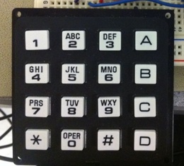
We used a 16-key 8-pin keypad (seen on left) to read commands. Each button on the keypad would issue one command. The keypad is wired as a matrix, so we can reliably read one key at a time by determining which column and row are connected.
-
3.Reading keyboard input from a keyboard
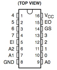
We wired the keyboard as 23 independent switches. The STK-500 would not have that many free pins, however, so we used priority encoders to encode the key signals. We split the keys into 3 sections of 8 and used 8-3 encoders to get 4 outputs for each section (12 outputs total). We combined these signals through basic digital logic to get 6 outputs that we could hook up to the STK-500.
-
4.Storing notes for each track
We used a simple C array to store the key numbers we captured during recording. Note that this is an array and not a matrix; due to the limited number of connections on the STK-500, we cannot capture every piano key at the same time, so we only play/record one note at a time. We capture ~10 notes/sec and record up to ~13 seconds, resulting in 128-length arrays for each track.
-
5.Printing to an LCD
We used a 16x2 LCD to display messages to the user. Conveniently, we were able to use a library (lcd_lib.h) that could print strings to the LCD. So our output consisted of updating our global output strings when necessary, and regularly writing those strings out to the LCD.
-
6.Managing the state machine that would control the keyboard
Our keyboard is controlled by a state machine that keeps track of what is going on at any given time. Most transitions between states are triggered by commands. We wrote a function handle_keypress(..) to examine what key was pressed and what state the keyboard is in and then transition to a new state and run any necessary code (for example, when a user presses a key to Delete all tracks, we have to run code that will erase the notes data).
-
7.Reading input/calculating output on time
Everything we needed this keyboard to do was time-sensitive. To simplify our lives, we used the TinyRealTime kernel. Everything except the PWM calculation and output is done by tasks that run periodically. For example, during recording, we capture notes at ~10 notes/sec. This is done by running a task that executes ~100ms. The code to schedule this task can be seen on the left.
Since TinyRealTime uses the Mega644’s timer1, we use timer0 for the PWM calculation and timer2 for the PWM output. The PWM output runs at 62.5kHz, but the calculations take longer, so we run those with timer0 in an interrupt that runs every 8kHz. This combines the benefits of a high PWM frequency (don’t have to worry about filtering an audible frequency) and slower calculation frequency (takes less CPU time by running less frequently).

Overall, our keyboard is a decent attempt at a basic synthesizer. Although the notes that can be played with the keyboard synthesizer are relatively good representations of the actual instrument, the differences between the two are audibly evident; it helps to be imaginative when using our keyboard. The keyboard creates sounds that are reminiscent of the instrument but aren’t quite perfect. We knew that we wouldn’t be able to get the sounds to exactly match the sounds that the actual instruments could produce, but the sounds we were able to produce exceeded our expectations. The two sounds that are closest to their instrument equivalent are the xylophone and the brass instrument, while the guitar sound is less believable. The robotic sound has nothing to compare to, so that could be considered authentic.
Now let’s get into specific user interaction performance. These analyses are subjective. The keyboard seems quite responsive, with the LCD updating nearly immediately. Due to our method of updating the display, sometimes the display will temporarily settle between two messages, displaying half of each. This could have been avoided with a semaphore protecting the output buffers, but it’s rather minor. According to the PWM math, the frequencies we output are accurate to ~.2Hz, since the lowest frequency we could output is .12Hz. When measured using the oscilloscope, the frequencies come to within 10 Hz of the desired frequencies (we can’t measure much better with the scope in lab). Additionally, the frequency we want to play has always resulted in the correct frequency being played. Chords sound subjectively good, even octaves.
Our project didn’t involve much anything dangerous. Nonetheless, our design emphasized safety in two specific areas: soldering and sanding. While using the soldering iron, we made sure we were wearing our safety goggles and worked together whenever soldering to ensure safety. We also made sure that the soldering iron was turned off after every use. While sanding, we made sure we turned on the fan to prevent dust particles from filling the air, and we also wore safety goggles and worked as a pair. In an effort to be as safe as possible with the STK-500 board, we made sure that the board wasn’t near flammable material in the case that the board overheated.
Our keyboard needed to be tested aloud using speakers, which could interfere with other groups who are designing projects that attempt to use sounds in some processing manner (or who would be annoyed by random noises). We greatly reduced the risk of interference by keeping our speakers on as low as we could. This was also done to protect the speakers from nefarious code.
The user interface we designed for the project consists of a LCD that tells the user exactly what every press on the keypad. Any English-literate user should be able to operate the keyboard and keypad with relative ease, even without supervision. The key to this is the help mode, which is activated by pressing button 9 and gives a basic description of what every button on the keypad. A message is placed on the LCD whenever the STK-500 is turned on that prompts the user to press the help key. Due to this feature, it is possible for any English-literate user to operate the keyboard system with no external guidance.

Software Details
In this section we will give detailed explanations for how certain software objectives were accomplished:
1. Reading the keypad
2. Transitioning between various states
1. Reading the keypad
The reading of the keypad button press was similar to the code used in lab 2 of ECE4760 in which the row are driven to zero, the columns are read, the rows and columns are reset, the columns are then driven to zero, and the rows read. From here, the unique eight-bit code yielded from the previous step is compared to a key code table to determine which button push it responds to, ranging from button zero to fifteen.
2. Transitioning between various states
The keypad presses were governed by a task that called a state machine. The state machine would have its only input be the key pressed. On a key press, the state of the state machine would be updated, the message of what was happening would print to the LCD, and a function would be called. The states that the state machine could be in include Normal_State, Help_State, Recording_State, and Playback_State. Normal_State was assumed when the state machine is initialized and will take in any key and act accordingly. Help_State is activated when key 10 is pressed (corresponds to button 9 on the keypad) while the state machine is in Normal_State and stays in Help_State until key 10 is pressed for a second time. While in Help_State, pressing any key will give the user information via a message on the LCD about that key. Recording_State is entered whenever the record button is pressed (the asterisk on the keypad) and remains in the Recording_State until exited via button 8 (key 9). While in Recording_State, the notes played using the keyboard are saved in an array for later playback.
Hardware Details
Here we will explain how we solved the hardware problems we found:
-
1.Getting keyboard signals onto the STK-500
-
2.Getting signals out of the keyboard itself
-
3.Encoding the signals between the keyboard and the STK-500
-
4.Reading the command keypad
-
5.Printing messages on the LCD
-
6.Using separate sound envelopes for the four instruments
-
7.Low-passing the output
1. Getting keyboard signals onto the STK-500
One of the main problems we ran into involved utilizing the limited number of input ports of the STK-500. The keyboard we wanted to design came with 23 keys, which meant we would need a coded input to those ports with a unique signature for every port input. The way we sought about accomplishing this involved using encoders for our key presses. However, 23 unique keys required three encoders and nine inputs to the STK-500 ports, which was too many due to our use of an LCD and keypad that helps the user interact with the keyboard. In an effort to limit the number of inputs we used, we created a Boolean circuit using the output of our encoders to create a unique code for every key press on the keyboard.
2. Getting signals out of the keyboard itself
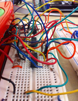
We annihilated the interconnects of the circuit of the board we bought and instead used each key as a one-hot switch. We did this by connecting the bottoms of all of the switches to a ground and soldering wires to the top of every switch. By connecting the power source to a 1k resistor and connecting that to the switch, we are able to get an active low switch. When we combined this with the encoders to create a twelve-bit code that could be fed into the STK-500. This code acted as a key code which key on the keyboard was pressed and allows for the keys to be decoded.
3. Encoding the signals between the keyboard and the STK-500
The keyboard we used gave us only a simple switch in the form of a short, so we needed to take this value and have it fed from VCC and through a resistor (which we chose to be 1k). This allowed us to make each press of the keyboard act as a switch, and we took this switch and fed the wire to the encoder input.
Each encoder took 8 inputs out produced 4 outputs, so a total of 12 wires were fed into the STK-500. On the STK-500, we use a simple decoding process to determine which key was pressed.
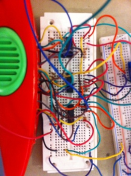
Something we tried that did not work was further encoding the outputs through a NAND to reduce the number of outputs we would have to wire into the STK-500. The three encoders each produced their own A0,A1,A2 outputs. However, if only one key is pressed at a time, these can be combined since they would stay high while the more important octave that gets a keypress pulls the output low. So we put these into 3 3-input NANDS. Unfortunately, the NAND chips we had in lab were of poor quality: the pins were corroded and the readings seemed unreliable. Fortunately, we realized we had enough inputs on the STK-500 for 12 signals, so we simply put all encoder outputs onto the board.
4. Reading the command keypad
The hardware design for the keypad was based off of the hardware design from lab 2 of ECE4760. The keypad is hooked up to the STK-500 through an input/output port so the software can switch the rows and columns of the matrix between inputs and outputs.
5. Printing messages on the LCD
The hardware design for the LCD was based off of the hardware design from lab 1 of ECE4760. The pins are simply connected to an output port on the STK-500. The libraries we used were sufficient for our uses.
-
6.Using separate sound envelopes for the four instruments
We unfortunately did not get to use different sound envelopes for the different instruments. Our envelopes were precomputed and stored in tables for fast access during the PWM calculation. The limited memory on the Mega644 forced us to back down to a single envelope that would control all four instruments.
-
7.Low-passing the output
The output of the STK-500 is going to have harsh harmonics due to ramping. In order to fix this, we make use of a low pass filter with a corner frequency around 100 Hz that will account for these harsh harmonics and help smooth the sound out.

The resemblance of the digitally created sound waves to the actual sound waves far exceeded our expectations. The sound waves were created using a variety of methods, including direct digital synthesis, frequency modulation, and additive synthesis. If we had another chance to do this project, one thing we might change would be to choose all of the instruments to be ones that can be synthesized by a single method rather than by multiple types of synthesis.
Another thing that was time consuming yet yielded no results was our attempt to decode the Schylling keyboard’s circuit board. The circuit didn’t seem to adhere to any specific rules regarding the decoding of a pressed key. On any pressed key, one bus of the wire would go high, indicating that a key in a specific octet was pressed. The only other wires on the board, however, were three wires that traveled to the microcontroller and would all drop to the same voltage at the same time. After spending hours trying to determine what each of the three wires did, we were unable to confirm anything except that these wires were identical to the best of our knowledge. We decided that it wouldn’t be fruitful to continue in this endeavor and instead acted to obliterate the wires connecting all of the switches to one another, making every button act as a simple switch. Had we decided to do this at the beginning of the project, we may have finished a full week earlier.
Any code that we used on this project that we did not create ourselves came from Bruce Land. This includes code from lab 2 in which we used the section that scans the key pad and gets a key code for the button pressed, as well as the code that makes the LCD work and print properly. Additionally, we heavily relied upon and used parts from the tiny real time page and the DSP page that are linked to the ECE4760 homepage.
We publicly credit Bruce Land for the code and help we received from him, as well as the companies who created the data sheet that we were able to download. Those include Texas Instruments for the 8 to 3 SN74HC148 encoders. There exist no conflicts of interest between our group and any company of any product used in this project. Neither of us is employed nor will be employed by said companies or competitors of said companies. We acknowledge that our synthesizer is not nearly up to the same standard as professionally made keyboard synthesizers, in both audio quality and musical selections and scales. Throughout the weeks of designing this project, we were always overly cautious when it came to safety and we always acted to keep the welfare and safety of the rest of our lab participants. Whenever we worked with the soldering iron, we checked to make sure the soldering station was cleared of any potential fire hazards and that water was available on hand in case of any unforeseen accidents. We also made sure that our soldering was completed as close to the fan as possible to ensure that the potentially hazardous smoke emitted from the burning solder was quickly dispersed. Additionally, we purchased a Schylling keyboard for the sole purpose of academic enrichment and have no intent to resell this product or create any type of similar product for monetary gain.

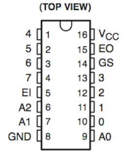
The 8-3 encoder used to reduce the inputs
Encoder datasheet and vendor:
http://focus.ti.com/lit/ds/symlink/sn74hc148.pdf
http://search.digikey.com/scripts/DkSearch/dksus.dll?Detail&name=296-8233-5-ND
TinyRealTime kernel information:
http://people.ece.cornell.edu/land/courses/ece4760/TinyRealTime/index.html
Frequency modulation and additive synthesis information:
http://people.ece.cornell.edu/land/courses/ece4760/Math/avrDSP.htm
16x2 LCD information:
http://people.ece.cornell.edu/land/courses/ece4760/labs/s2011/lab1.html
16-key 8-pin keypad information:
http://people.ece.cornell.edu/land/courses/ece4760/labs/s2011/lab2.html
PWM diagram by Cyril Buttay:
http://en.wikipedia.org/wiki/File:Pwm.png
All other pictures were taken by us of hardware we used in this project, except for those bottom two, which were taken by Bruce Land.


The encoder (74LS148) we used in our circuit. So in the encoder for the bottom 8 keys, we attach the switches to inputs 0-7, then read A0,A1,A2,EO.


We accomplished most tasks together, but we played to our strengths and did the tasks alone that would have taken longer together. Matt did much of the soldering and sanding, since he was much better at it than Alec (although Alec assisted in preparing and holding wires). On the other hand, Alec wrote the core state machine code (including those crucial macros) and the core synthesis/envelope code. Matt spent the time figuring out what instruments would sound best with our synthesis techniques and wrote the code that initialized the wavetables. Matt designed the encoding circuit that connected the keyboard to the STK-500 through encoders. Alec wrote the code that kept the tasks running on time, and ensured we did not use too much memory (which causes the Mega644 to hang, or restart, depending on the weather). For the most part, the hardware was tackled by Matt while the software was done by Alec.
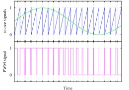
A digital signal (pink) can create a sine wave (blue)
A 16-key 8-pin keypad
A 16x2 LCD
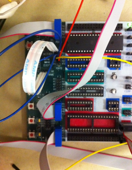
Our encoder circuit, showing the 8-3 encoders.
Our low-pass filter, showing the PWM input (red), resistor, capacitor, and speaker output (yellow).
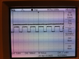
The rectangular PWM waveform running at 62.5kHz.
An example of a state transition in our code. When key 10 is pressed while in the Normal Mode, we print “Help Mode on” to the LCD, transition to the Help Mode, and do nothing further.
Code example showing scheduling of a task that will run between .1 and .125 seconds in the future.
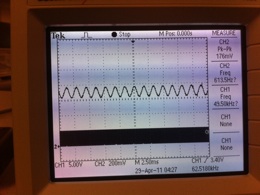
The sine wave (613.5Hz) from the filtered PWM.
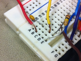
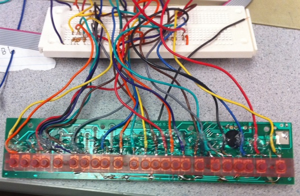
The printed circuit board we used from the piano. We destroyed the existing key matrix since we couldn’t reliably decode it, and soldered our own wires to connect to the switches.
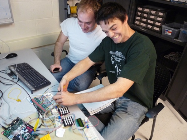
It turns out it was the red wire.
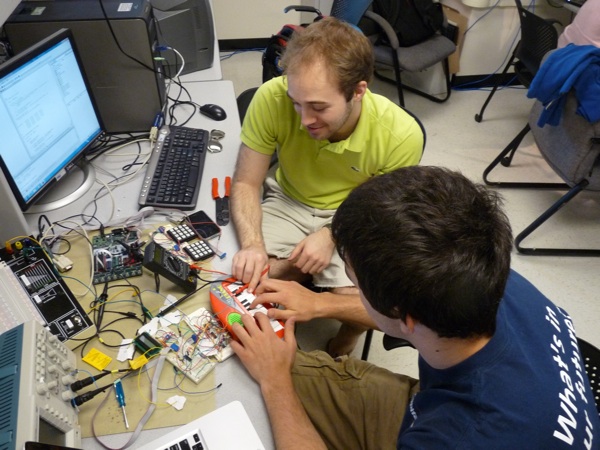
Saving the world one circuit at a time.